EP0803761A1 - Bobine étanche à la lumière - Google Patents
Bobine étanche à la lumière Download PDFInfo
- Publication number
- EP0803761A1 EP0803761A1 EP96106583A EP96106583A EP0803761A1 EP 0803761 A1 EP0803761 A1 EP 0803761A1 EP 96106583 A EP96106583 A EP 96106583A EP 96106583 A EP96106583 A EP 96106583A EP 0803761 A1 EP0803761 A1 EP 0803761A1
- Authority
- EP
- European Patent Office
- Prior art keywords
- coil
- side flanges
- tapes
- light
- opaque
- Prior art date
- Legal status (The legal status is an assumption and is not a legal conclusion. Google has not performed a legal analysis and makes no representation as to the accuracy of the status listed.)
- Withdrawn
Links
- 239000000463 material Substances 0.000 claims abstract description 46
- 239000000853 adhesive Substances 0.000 claims description 21
- 230000003313 weakening effect Effects 0.000 claims description 18
- 230000001070 adhesive effect Effects 0.000 claims description 14
- 239000004698 Polyethylene Substances 0.000 claims description 7
- 229920000573 polyethylene Polymers 0.000 claims description 7
- -1 polyethylene Polymers 0.000 claims description 5
- 238000007789 sealing Methods 0.000 claims description 4
- 239000011248 coating agent Substances 0.000 claims description 3
- 238000000576 coating method Methods 0.000 claims description 3
- 238000004519 manufacturing process Methods 0.000 claims description 3
- 238000000034 method Methods 0.000 claims description 3
- 239000004831 Hot glue Substances 0.000 claims description 2
- 239000002131 composite material Substances 0.000 claims description 2
- 239000004922 lacquer Substances 0.000 claims description 2
- 239000002390 adhesive tape Substances 0.000 claims 1
- 239000010410 layer Substances 0.000 description 5
- 238000004806 packaging method and process Methods 0.000 description 3
- 239000004820 Pressure-sensitive adhesive Substances 0.000 description 2
- 238000004026 adhesive bonding Methods 0.000 description 2
- 239000012790 adhesive layer Substances 0.000 description 2
- 230000002093 peripheral effect Effects 0.000 description 2
- 230000037303 wrinkles Effects 0.000 description 2
- 238000005452 bending Methods 0.000 description 1
- 230000001419 dependent effect Effects 0.000 description 1
- 238000011161 development Methods 0.000 description 1
- 230000018109 developmental process Effects 0.000 description 1
- 238000003780 insertion Methods 0.000 description 1
- 230000037431 insertion Effects 0.000 description 1
- 229920001296 polysiloxane Polymers 0.000 description 1
- 238000003825 pressing Methods 0.000 description 1
- 238000000926 separation method Methods 0.000 description 1
- 238000003466 welding Methods 0.000 description 1
Images


Classifications
-
- G—PHYSICS
- G03—PHOTOGRAPHY; CINEMATOGRAPHY; ANALOGOUS TECHNIQUES USING WAVES OTHER THAN OPTICAL WAVES; ELECTROGRAPHY; HOLOGRAPHY
- G03B—APPARATUS OR ARRANGEMENTS FOR TAKING PHOTOGRAPHS OR FOR PROJECTING OR VIEWING THEM; APPARATUS OR ARRANGEMENTS EMPLOYING ANALOGOUS TECHNIQUES USING WAVES OTHER THAN OPTICAL WAVES; ACCESSORIES THEREFOR
- G03B27/00—Photographic printing apparatus
- G03B27/32—Projection printing apparatus, e.g. enlarger, copying camera
- G03B27/52—Details
- G03B27/58—Baseboards, masking frames, or other holders for the sensitive material
- G03B27/587—Handling photosensitive webs
- G03B27/588—Supply rolls; Cutting arrangements
Definitions
- the invention relates to an opaque spool with an opaque spool core and side flanges arranged on both sides thereof, on which spool core a photosensitive material web is wound, with an opaque wrapping part, the width dimension of which is at least approximately equal to the width dimension of the material web, envelops the material web and at an end region with the Photosensitive material web is connected, with opaque fastener tapes made of a flexible material, each forming an opaque bridge between one of the side flanges and the wrapping part, wherein each fastener tape rests light-tight on the wrapping part in an elastically stretched state and is not tear-off connected to the same is and is light-tight on a second portion on one of the side flanges, and a method for manufacturing.
- opaque packed coils with light-sensitive material which are suitable for charging devices in daylight, are already known.
- the loading or insertion of films or light-sensitive papers must be possible in the rooms in which the relevant devices are installed or used, which is why one speaks of room light charge packaging for light-sensitive materials.
- the common packaging of this type has the disadvantage that the side flanges used protrude laterally or in diameter over the spool and therefore graze in the film cassette, thereby preventing the unwinding of the light-sensitive material, and furthermore, when the opaque wrapping part is pulled off, parts of the packaging torn loose in the Film cassettes are left behind and soiled or even cause interference, and that the beginning of the wrapping part is often inconvenient to insert into the outlet or guide slot of the film cassette and is difficult to pull through.
- EP-A-0 599 001 shows an opaque coil in which the two side flanges, which are preferably made of polyethylene, are attached to the end faces of the coil and are bent in the area of the coil core toward the latter.
- This offset is achieved, among other things, by pressing or thermal deformation.
- the cranked sections do not always fit perfectly against the inside of the coil, and that these ends, which form a shoulder on the inside of the coil core, may be caused by an object inserted into the coil core, e.g. a carrier or a shaft are torn open.
- the object of the invention is to provide an opaque coil which does not have the disadvantages mentioned and is easy to manufacture.
- FIG. 1 shows an opaque coil 1 with light-sensitive material, with an opaque coil core 2, ring-shaped, opaque side flanges 3 and 4 attached on both sides to the end faces of the coil 1, an opaque wrapping part 5, which forms a sheathing for the light-sensitive material and also opaque , elastically stretchable fastening tapes 6 and 7, which connect the sheathing to the side flanges 3, 4 on both sides in an opaque manner and thus form an opaque bridging.
- the covering part 5 has a tab 8, with the aid of which the translucent covering can be torn open and the covering part 5 can be removed.
- the fastening tapes 6, 7 can have weakening lines 9 which run in the circumferential direction and act as predetermined tear points, as well as a large number of further weakening lines 10 which run obliquely to the circumferential direction and which facilitate the start of the removal of the wrapping part 5 from the coil.
- FIG. 1 shows lines of weakness 9 which lie on the covering part 5, but solutions can also be used just as well in which the lines of weakness 9 lie on the side flanges 3, 4 (not shown). Lines of weakness of this type can be, for example, perforations, slots, notches or the like.
- the fastener tapes 6, 7 are also preferably provided with a self-adhesive layer.
- a partial cross section according to FIG. 2 shows the structure of the coil 1.
- Photosensitive material 11 is wound on the coil core 2.
- the side flanges 3, 4 consist of light-tight cardboard, e.g. with a maximum thickness of 0.5 mm, and have the shape of a circular ring. In the area of their inner circumference, they are connected to the respective end faces of the coil core 2 by means of an adhesive, advantageously a hot-melt adhesive, in the sense of a butt connection, as is shown in FIG. 2 by the arrows 19 and 20.
- the side flanges 3, 4 can have a film or lacquer coating.
- the outside diameter of the side flanges 3, 4 is insignificantly smaller than the diameter of the wound light-sensitive material, ie the film spool.
- the inner diameter of the annular side flanges 3, 4 is slightly larger than the upper tolerance value for the core inner diameter, which is permitted according to the ISO standard. This ensures that even with small inaccuracies in the position of the annular side flanges 3, 4, they do not protrude either outside or inside.
- the side flanges 3, 4 are welded or sealed on the end face of the coil core by means of heat and pressure.
- the wrapping part 5, which forms the opaque sheathing of the coil 1 has essentially the same width as the wound light-sensitive material.
- the sealing tapes 6, 7 are attached in the edge region of the coil 1 between the covering part 5 and the side flanges 3, 4 and bring about a complete opaque seal.
- Each of the fastener tapes 6, 7 is divided into two partial areas, of which a first partial area 12 lies essentially on the covering part 5 and a second partial area 13 essentially lies on the respective side flange 3, 4.
- the first section 12 of the respective fastener tape 6, 7 is in a stretched state not tear-off connected to the covering part 5.
- the second partial region 13 of the respective closure tape 6, 7 can be connected to the respective side flange 3, 4, for example by means of an adhesive connection.
- the second sub-area lies opaque on the side flange using adhesive forces.
- the second partial area 13 is kept as small as possible. It has been shown that a complete overlap in the range from 3 to 6 mm of the closure tapes 6, 7 with the side flanges 3, 4 is sufficient to form the second partial areas 13 even with large coils (diameter in the range of 10 cm).
- the second partial area 13 is not tear-off from the respective side flange 3, 4, for example with an adhesive connection.
- the first and the second partial areas 12, 13 of the respective fastener tape 6, 7 can be separated from one another along the respective weakening line 9 when the covering part 5 is pulled off the spool 1 with the aid of the tab 8.
- the lines of weakness 9 are each attached to the fastener tapes 6, 7 in such a way that they already lie either on the covering part 5 or on the side flanges (3, 4) near the edge.
- the sealing tapes 6, 7 are preferably opaque polyethylene tapes, the adhesiveness of which is in the range of 7-8 g / mm 2 .
- Figure 3 shows the arrangement of the fastener tapes 6, 7 on an embodiment (see also Fig. 1 and 2), which is provided with lines of weakness 9 on the covering part 5.
- the weakening lines 9 run in the peripheral area on the covering part 5 in the circumferential direction.
- the further weakening lines 10 run obliquely to the weakening lines 9 in the direction in which the wrapping part 5 is pulled off with the aid of the tab 8 will, however, not reach all the way to the weakening lines 9.
- the fastening tapes 6, 7 are attached in exactly the same way, however, it should then be advantageously ensured that the ends of the fastening tapes 6, 7 lie in the area of the tab 8 so that the removal of the covering part 5 is not made more difficult.
- the covering part 5 is so long that it can cover itself on the circumference of the coil 1 and is provided in the area of the tab 8 with an adhesive point which is designed as a release area 14 (see also FIG. 4). At the gluing point, the wrapping part 5 is attached to itself.
- FIG. 4 shows the covering part 5 and its connection with the light-sensitive material 11 of the coil 1 in detail.
- the covering part is a layer composite of an outer and an inner layer 15, 16 which adhere to one another and between which the light-sensitive material 11 is fastened in an end region 17.
- the outer layer 15 is preferably made of a self-adhesive material, e.g. from a self-adhesive paper.
- Inner layer 16 is preferably made of a siliconized material, e.g. made of a silicone paper that adheres to the self-adhesive material. If self-adhesive paper is used, it can of course be printed as desired.
- the wrapping part 5 tapers increasingly towards the tab 8 (see FIGS. 1 and 3) and has in the region thereof the release region 14, a point at which the siliconized material, or the inner layer 16, is missing.
- the closure tapes 6, 7 have a straight, serrated or corrugated shape at their edges in the second partial area 13, which rests on the respective side flange 3, 4.
- the corresponding shape depends on the material selected.
- the shape is intended to ensure that the fastener tapes 6, 7 rest on the respective folds without wrinkles Favor side flanges 3, 4. This can make inserting and unwinding of the spools considerably easier, particularly in the case of closely tolerated film cassettes, since there is no unnecessary friction due to wrinkling.
- the fastener tapes 6, 7 are applied to the coated spool in the edge area between the covering part 5 and the side flanges 3, 4 in a single operation. Before application, the fastening tapes 6, 7 are stretched elastically. The first subregions 12 of the fastener tapes 6, 7 are fastened on the wrapping part 5 in the elastically stretched state, for example by gluing. The likewise elastically stretched second partial areas 13 are placed on the respective side flanges 3, 4. The second sections 13 can be attached to the side flanges 3, 4 with an easily detachable adhesive layer.
- a pressure-sensitive adhesive coating of the second partial areas 13 is not absolutely necessary, however, since the stretched material of the fastener tapes forms a positive connection with its restoring force at the edges of the side flanges 3, 4, the adhesive forces occurring between the fastener tapes 6, 7 and the side flanges 3, 4 form a light-tight and non-shifting closure.
- the application of the fastener tapes 6, 7 in the stretched state causes them to lie practically wrinkle-free in the second partial areas 13, since the restoring forces largely prevent wrinkles from occurring at all.
- the fastening tapes 6, 7 consist of a flexible material that is elastically stretchable.
- a flexible material that is elastically stretchable.
- PE polyethylene
- the closure tapes 6, 7 are also advantageously so thin and flexible that they can be effortlessly pulled together with the covering part 5 from the outlet or guide slot of the film cassette.
- the stretching of the fastener tapes 6, 7 used during the application is preferably in the range from 5 to 15%.
- Suitable Combinations of elastic properties in the case of elastically stretchable materials and the stretch used are preferably in a range which only allows about 10% permanent change in shape.
- a coil 1 with light-sensitive material which is provided with weakening lines 9 on the covering part 5 (see FIG. 3), is torn open at the tab 8, the further weakening lines 10 facilitate the tearing of the fastener tapes 6, 7, and the in Weakening lines 9 extending in the circumferential direction ensure the controlled separation of the opaque sheathing.
- the covering part 5 is pulled off the coil 1, the edges of the sealing tape parts 6, 7 remaining on the side flanges 3, 4 are bent radially away from the coil 1 and subsequently remain plastically deformed in this position due to the overstretching. They no longer interfere with the further unwinding of the light-sensitive material. This is important because the photographic properties of films or other photosensitive material can be affected by stripped adhesive residues, resulting from this Way is largely prevented.
- closure tapes 6, 7 can also be used in which no adhesive is applied in the immediate vicinity of the weakening line 9.
- fastener tapes 6, 7 can be glued on, but other types of fastening can also be used, for example spot welding or similar methods, provided the fastener tapes 6, 7 as well as the covering part 5 consist of suitable materials.
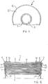
- FIG. 5 A second embodiment of the invention is shown in the drawing figures 5 and 6.
- circular side rings 21, 22 are additionally arranged on the side flanges 3, 4.
- These side rings 21, 22 are preferably made of polyethylene (PE) and are provided with a weak pressure sensitive adhesive.
- a so-called telescoping of the finished coil i.e. prevent lateral shifting of the uppermost turns of the light-sensitive material.
- Such a lateral shifting could prevent the fastener tapes 6, 7 from bending sideways and thus prevent the incidence of light.
Landscapes
- Physics & Mathematics (AREA)
- General Physics & Mathematics (AREA)
- Packaging Of Annular Or Rod-Shaped Articles, Wearing Apparel, Cassettes, Or The Like (AREA)
- Storage Of Web-Like Or Filamentary Materials (AREA)
- Packages (AREA)
Priority Applications (1)
| Application Number | Priority Date | Filing Date | Title |
|---|---|---|---|
| EP96106583A EP0803761A1 (fr) | 1996-04-26 | 1996-04-26 | Bobine étanche à la lumière |
Applications Claiming Priority (1)
| Application Number | Priority Date | Filing Date | Title |
|---|---|---|---|
| EP96106583A EP0803761A1 (fr) | 1996-04-26 | 1996-04-26 | Bobine étanche à la lumière |
Publications (1)
| Publication Number | Publication Date |
|---|---|
| EP0803761A1 true EP0803761A1 (fr) | 1997-10-29 |
Family
ID=8222715
Family Applications (1)
| Application Number | Title | Priority Date | Filing Date |
|---|---|---|---|
| EP96106583A Withdrawn EP0803761A1 (fr) | 1996-04-26 | 1996-04-26 | Bobine étanche à la lumière |
Country Status (1)
| Country | Link |
|---|---|
| EP (1) | EP0803761A1 (fr) |
Citations (2)
| Publication number | Priority date | Publication date | Assignee | Title |
|---|---|---|---|---|
| EP0599001A1 (fr) * | 1992-11-20 | 1994-06-01 | Typon Aktiengesellschaft Für Photographische Industrie | Bobine de matériau photosensible emballée à l'abri de la lumière et procédé de fabrication |
| EP0644457A1 (fr) * | 1993-09-17 | 1995-03-22 | Agfa-Gevaert N.V. | Emballage de film opaque à la lumière |
-
1996
- 1996-04-26 EP EP96106583A patent/EP0803761A1/fr not_active Withdrawn
Patent Citations (2)
| Publication number | Priority date | Publication date | Assignee | Title |
|---|---|---|---|---|
| EP0599001A1 (fr) * | 1992-11-20 | 1994-06-01 | Typon Aktiengesellschaft Für Photographische Industrie | Bobine de matériau photosensible emballée à l'abri de la lumière et procédé de fabrication |
| EP0644457A1 (fr) * | 1993-09-17 | 1995-03-22 | Agfa-Gevaert N.V. | Emballage de film opaque à la lumière |
Similar Documents
| Publication | Publication Date | Title |
|---|---|---|
| DE68910402T2 (de) | Verpackte aufgewickelte Bahn lichtempfindlichen Materials und Verfahren zum Verpacken. | |
| DE69117650T2 (de) | In Endlosrollenform aufgewickeltes Verbundstoffklebeband und Verfahren zur Herstellung dieses Bandes | |
| DE2415380C2 (de) | Verschluß für eine Wegwerfwindel | |
| DE69407822T2 (de) | Verbindungsklebeband, verfahren zum verbinden und spleiss mit dem verbindungsklebeband | |
| DE1932287A1 (de) | Sterile Packung fuer chirurgisches Nahtmaterial | |
| DE69829884T2 (de) | Anbringen einer lasche auf einer klebebandrolle und artikel | |
| DE1574346B2 (de) | Haftstreifen | |
| EP0566880A1 (fr) | Dispositif pour raccorder des bandes successives de papier enroulées en bobines | |
| DE4337368A1 (de) | Lichtdichte Verpackung von bahnförmigem lichtempfindlichen Material | |
| CH635797A5 (de) | Verpacktes verbands-heftpflaster und einrichtung zu deren herstellung. | |
| DE19830954A1 (de) | Lichtdichte Verpackung für streifenförmiges lichtempfindliches Material | |
| EP0632322B1 (fr) | Emballage étanche à la lumière pour produit photosensible en bande | |
| DE69723378T2 (de) | Lichtdichte Verpackung mit perforierten Stirnscheiben | |
| US5515970A (en) | Light-tight package | |
| DE69619920T2 (de) | Wickelrolle mit Verschlussstreifen | |
| EP0710878A1 (fr) | Emballage étanche à la lumière | |
| WO2001032526A1 (fr) | Procede d"emballage d"objets et materiau d"emballage en forme de bande | |
| EP0599001A1 (fr) | Bobine de matériau photosensible emballée à l'abri de la lumière et procédé de fabrication | |
| DE69629168T2 (de) | Lichtdichte Verpackung | |
| EP0233840B1 (fr) | Cassette de film | |
| EP0536608B1 (fr) | Noyau d'enroulement opaque à la lumière | |
| DE3044808A1 (de) | Kassette mit spule und einem befestigungsband fuer einen materialstreifen | |
| DE2721135A1 (de) | Verfahren zum befestigen einer schutzfolie | |
| EP0562212B1 (fr) | Procédé pour produire un long film à partir d'une pluralité de rubans courts de film photographique | |
| EP4334405A1 (fr) | Système de bande de matériau, ensemble système de bande de matériau, procédé de production d'un ensemble système de bande de matériau et utilisation d'un système de bande de matériau |
Legal Events
| Date | Code | Title | Description |
|---|---|---|---|
| PUAI | Public reference made under article 153(3) epc to a published international application that has entered the european phase |
Free format text: ORIGINAL CODE: 0009012 |
|
| AK | Designated contracting states |
Kind code of ref document: A1 Designated state(s): CH DE ES FR GB IT LI |
|
| AX | Request for extension of the european patent |
Free format text: AL;LT;LV;SI |
|
| 17P | Request for examination filed |
Effective date: 19971121 |
|
| RBV | Designated contracting states (corrected) |
Designated state(s): CH DE ES FR GB IT LI |
|
| 17Q | First examination report despatched |
Effective date: 20020620 |
|
| STAA | Information on the status of an ep patent application or granted ep patent |
Free format text: STATUS: THE APPLICATION IS DEEMED TO BE WITHDRAWN |
|
| 18D | Application deemed to be withdrawn |
Effective date: 20021031 |