EP0803843B1 - Appareil pour le traitement d'images en coupe d'échantillons osseux comprenant des parties corticales et spongieuses - Google Patents
Appareil pour le traitement d'images en coupe d'échantillons osseux comprenant des parties corticales et spongieuses Download PDFInfo
- Publication number
- EP0803843B1 EP0803843B1 EP97105299A EP97105299A EP0803843B1 EP 0803843 B1 EP0803843 B1 EP 0803843B1 EP 97105299 A EP97105299 A EP 97105299A EP 97105299 A EP97105299 A EP 97105299A EP 0803843 B1 EP0803843 B1 EP 0803843B1
- Authority
- EP
- European Patent Office
- Prior art keywords
- image
- bone
- roi
- pixels
- bone portion
- Prior art date
- Legal status (The legal status is an assumption and is not a legal conclusion. Google has not performed a legal analysis and makes no representation as to the accuracy of the status listed.)
- Expired - Lifetime
Links
Images


Classifications
-
- G—PHYSICS
- G06—COMPUTING OR CALCULATING; COUNTING
- G06T—IMAGE DATA PROCESSING OR GENERATION, IN GENERAL
- G06T7/00—Image analysis
- G06T7/0002—Inspection of images, e.g. flaw detection
- G06T7/0012—Biomedical image inspection
-
- G—PHYSICS
- G06—COMPUTING OR CALCULATING; COUNTING
- G06T—IMAGE DATA PROCESSING OR GENERATION, IN GENERAL
- G06T7/00—Image analysis
- G06T7/10—Segmentation; Edge detection
- G06T7/11—Region-based segmentation
-
- G—PHYSICS
- G06—COMPUTING OR CALCULATING; COUNTING
- G06T—IMAGE DATA PROCESSING OR GENERATION, IN GENERAL
- G06T7/00—Image analysis
- G06T7/60—Analysis of geometric attributes
- G06T7/62—Analysis of geometric attributes of area, perimeter, diameter or volume
-
- G—PHYSICS
- G06—COMPUTING OR CALCULATING; COUNTING
- G06T—IMAGE DATA PROCESSING OR GENERATION, IN GENERAL
- G06T7/00—Image analysis
- G06T7/60—Analysis of geometric attributes
- G06T7/66—Analysis of geometric attributes of image moments or centre of gravity
-
- G—PHYSICS
- G06—COMPUTING OR CALCULATING; COUNTING
- G06T—IMAGE DATA PROCESSING OR GENERATION, IN GENERAL
- G06T2207/00—Indexing scheme for image analysis or image enhancement
- G06T2207/10—Image acquisition modality
- G06T2207/10072—Tomographic images
- G06T2207/10081—Computed x-ray tomography [CT]
-
- G—PHYSICS
- G06—COMPUTING OR CALCULATING; COUNTING
- G06T—IMAGE DATA PROCESSING OR GENERATION, IN GENERAL
- G06T2207/00—Indexing scheme for image analysis or image enhancement
- G06T2207/30—Subject of image; Context of image processing
- G06T2207/30004—Biomedical image processing
- G06T2207/30008—Bone
- G06T2207/30012—Spine; Backbone
Definitions
- the invention relates to a bone morphometric method, in particular, to a method of processing a sectional image of a sample bone which includes a cortical bone portion and a cancellous bone portion.
- the morphologies of human bones are measured to evaluate the strength of bones, to diagnose and determine the degree of progress of bone diseases such as osteoporosis and osteomalacia, or to confirm a therapeutic effect.
- the DEXA Dual Energy X-ray Absorptiometry
- the MD Micro Densitometry
- the DEXA and MD methods measure the amount or the density of bone mineral to diagnose the reduction of bone strength based on an assumption that there is a correlation between the amount or the density of bone mineral and the bone strength.
- the amount or the density of bone mineral does not precisely present the bone strength since bone structure significantly affects the bone strength.
- an attempt has been developed to evaluate the bone strength based on a postulate that bone strength depends significantly on the bone structure as well as bone mineral.
- sectional bone structural analysis is known in the art.
- a sectional image of a bone is provided by a micrograph or a X-ray computed tomography of a sample bone, and is used for measuring various parameters, such as, the sectional area and the perimeter, for evaluating structural anisotropy in the bone portion (refer to "Journal of Japanese Society of Bone Morphometry” Vol. 4, No. 1 Pages 83 - 89, 1994), and for the Node-strut method (refer to "Journal of Microscopy” Vol. 142, Pt3, Pages 341 - 349, 1986).
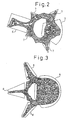
- Figure 1 is a schematic illustration of a vertebral body constituting a human spine.
- a static compressive force substantially acts on end faces of the vertebral body within areas 2 (only one in the top end face is shown in Figure 1) as shown by arrows 1. Therefore, during a bone morphometry, a subject region for analysis is defined on a sectional image of a sample bone, and within the subject region for analysis, various analyses, such as measurements of total area in the sectional bone image, mean wall thickness of the cortical bone and the cancellous bone portions, are carried out.
- the bone portion within the subject region is defined as a region of interest (ROI) so that various structural parameters are measured relative to the ROI.
- ROI region of interest
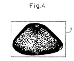
- FIG. 2 a sectional binary image of a vertebral body of a rat ( Figure 2), a micrograph of a vertebral body of a human ( Figure 3), and a sectional binary image of a femur of a rat ( Figure 4) are shown, respectively.
- Figures 2 and 3 enclosed by subject regions 3 and 4 for analysis, are the portions on which a static compressive force primarily acts.
- Figure 4 all of the sectional image is enclosed by a rectangle 5 as a subject region for analysis.
- the subject region for analysis are defined by configurations which have various shapes, sizes and orientations, for example, the rectangles 5 and 6, triangles 7 and 8, a sector 3, a circle and a configuration 4 combined thereby.
- a subject region for analysis is manually provided on a sectional image of a sample bone so that a human error is introduced into the size, shape, orientation, and position of the subject region.
- the human errors reduce the credibility and repeatability of the sectional bone structural analysis carried out based on such a manually provided subject region.
- the bone structure includes, in general, surface and internal structures.
- the internal structure further includes cancellous and cortical bone portions which have different functions.
- cancellous and cortical bone portions which have different functions.
- the cancellous and cortical bone portions must be considered separately to evaluate the internal bone structure.
- some apparatuses, for evaluating internal bone structure which can separate the cancellous and cortical bone portions from each other to measure and evaluate the respective portions independently.
- Such an apparatus binarizes a raw sectional bone image, which is produced by a micrograph or X-ray computed tomograph of a sample bone to provide an original binary image for processing to separate the sectional bone image into cancellous and cortical bone portions. Then, a filling hole operation is carried out on the original binary image within the peripheral of the bone sectional image to provide a solid image. The solid image is contracted until its area becomes half.
- a cancellous bone portion is provided by extracting the pixels which are common to the original binary image and the contracted solid image (referred to AND operation between the original binary image and the contracted solid image).
- a cortical bone portion is provided by extracting the pixels which are not common to the original binary image and the contracted solid image (referred to NAND operation of the original binary image and the contracted solid image).
- the above-mentioned prior art method defines the cancellous and cortical bone portions irrespective of the actual thickness of the cortical bone so that the structural evaluation based on the cancellous and cortical bone images thus provided cannot reflect the real bone strength.
- the invention is directed to solve the problems in the prior art, and to provide an improved method of processing a sectional bone image for using in a morphometry of a bone which includes a cortical bone portion and a cancellous bone portion.
- the invention provides a method of processing a sectional bone image of a sample bone as specified in claim 1 or 2 which method can eliminate a human error, as produced in the prior art, by providing a subject region on a binary image digitized from the sectional bone image automatically. Further, the invention provides a fine separation of the cortical bone portion and the cancellous bone portion so that the morphometry of the sample bone, in particular, the cancellous bone portion can be carried out with high precision and repeatability.
- a binary image of a bone section is provided to be processed.
- a subject region is provided on the binary image to producing a ROI image by extracting pixels corresponding to the bone portion from the binary image within the subject region, onto which ROI image the morphometry is carried out.
- a series of pixels which are on the center line extending along the cortical bone portion in the ROI image is determined.
- a hemi-cortical bone image is produced by using the determined center line.
- the hemi-cortical bone image has a wall thickness substantially half of the real wall thickness of the cortical bone portion.
- a template image for the cortical bone portion is produced by executing expanding operations on the hemi-cortical bone image with a predetermined number of times of operation.
- the template image for the cortical bone portion produced by expanding the hemi-cortical bone image by a number of times which is advantageously selected, defines precisely a region within which the cortical bone portion extends since the hemi-cortical bone image has a wall thickness substantially half of the real wall thickness of the cortical bone portion.
- the number of times for carrying out the expansion is preferably defined by INT(MWT ⁇ ⁇ + 1).
- ⁇ 2.0 is selected.
- the number of times for carrying out the expansion may be defined by INT(MWT ⁇ ⁇ + 1.5).
- extracting the pixels common to the ROI image and the template image provides an image substantially corresponding to the cortical bone portion, and eliminating the image corresponding to the cortical bone image from the ROI image provides an image corresponding to the cancellous bone portion. It will be understood that eliminating the pixels which are common to the ROI image and the template image from the ROI image can also provide an image corresponding to the cancellous bone portion.
- a tensor analysis of the image corresponding to the cancellous bone determines the structural anisotropy in the cancellous bone.
- the region of interest is provided by providing a subject region on the binary image as follows. First, the axis of inertia of the binary image of a vertebral body, and pixels corresponding to the vertebral canal within the binary image of a vertebral body are determined. The smallest rectangle enclosing the pixels of the vertebral canal is provided and a pair of fillet coordinates which are at the corners on one of the diagonals of the smallest rectangle enclosing the vertebral canal are determined.
- a subject region on the binary image is provided based on a representative length, which is defined by determining the distances between the axis of inertia and the fillet coordinates as the representative length, to extract pixels corresponding to the bone portion within the subject region, whereby the region of interest is defined on the binary image by the extracted pixels.
- the hemi-cortical bone image is provided as follows.
- An operation region to enclose the ROI image is provided so that the operation region including the largest and second largest background portion at either side of the ROI image bounds the center line pixels.
- the largest and second largest backgrounds within the operation region are determined, preferably, by a labeling operation to label holes which include pixels with zero (0) intensity. Pixels are determined as first pixels which are common with the largest hole image and the ROI image to provide a first hemi-cortical image, and as second pixels which are common with the second largest hole image and the ROI image to provide a second hemi-cortical image. Combining the first and second hemi-cortical images provides the hemi-cortical image.
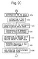
- a method of processing a sectional image of a sample bone according to an embodiment of the invention will be described.
- a sectional image of a sample bone is provided to be input into an image processing system according to the invention.
- an input raw image has a fine resolution, for example, lower than 20 ⁇ m per pixel, preferably lower than 10 ⁇ m per pixel.
- such a sectional image is obtained by a micro-focus X-ray computed tomography although another method, such as a micrograph of a slice of a sample bone can be utilized.
- An X-ray generator 14 includes a X-ray tube 14a of which the size of the focus area is approximately 8 ⁇ m and a rotating anode 14b.
- An X-ray sensor 16 and a slit 20 are provided apart from the X-ray generator 14 so that the slit 20 is positioned between the X-ray generator 14 and the X-ray sensor 16.
- An image reconstruction device 18 is electrically connected to the X-ray sensor 16 for receiving a signal corresponding to the intensity of the X-ray which reaches to the sensor 16.
- a sample bone 10 is disposed on a turntable 12 which is provided between the X-ray generator 14 and the slit 20.
- X-rays are produced when electron hits the rotating anode 14b, so that the accelerated X-ray is directed to the sample bone 10.
- the propagated X-ray is attenuated through the sample bone 10 - and reach the X-ray sensor 16 through the slit 20 so that X-rays which have the desired slice width are extracted from the propagated X-rays.
- the X-ray sensor 16 sends a signal to the image reconstruction device 18 corresponding to the intensity of the X-rays.
- the image reconstruction device 18 stores an information corresponding to the signal.
- the turntable 12 rotates through a predetermined angle to measure the sample bone 10 at the next rotational angle. The above process is repeated until the measurement is carried out along the full arc of the sample bone 10. Thereafter, the image reconstruction device 18 reconstructs a sectional image of the sample bone 10 based on the memorized information. Changing the level of the turntable 12 provides another sectional image of the sample bone 10 at a different height.
- the sectional image thus obtained may consist of 512 pixels x 480 pixels with each pixel sized 15 ⁇ m x 15 ⁇ m, and with CT value being expressed by a gradation of 2 16 . Further the CT value of the respective pixels is converted into a gradation of 2 8 by the following equation (1) when the image is input into the image processing system of the invention.
- TL INT(0.5 + ((CT value of the respective pixels) - (CT min ))/(CT max ) - (CT min )) x 255) where
- the image thus obtained is processed by the image processing system of the invention as described below.
- the image processing system 30 includes a computer 32 provided with a microprocessor (not shown) and memory devices (not shown) as known in the art.
- the image processing system 30 further includes a first or main display unit 34, such as a CRT display, for indicating text information, a second or additional display unit 36, such as a CRT display, for indicating the processed image, an output unit 38 such as a printer, and a key board 40.
- the system can include an additional memory device 42 such as an external hard drive unit or an magneto-optical disc drive.
- a display can be provided for indicating the text information and the processed image.
- the system may further include a pointing device 44, such as a mouse, a track ball, a touch panel or a light pen, for inputting a reference point necessary for the bone morphometry in the displayed image.
- step S10 a sectional image of a femur of a rat which is obtained by X-ray computed tomography is input into the image processing system as a raw image.
- step S12 the input raw image is binarized or digitized to provide a binary image of a bone section.
- the discriminant analysis method is used to provide the binary image as describe below.
- the pixels in an image are classified into two classes by a threshold value so that degrees of deviation of the intensity of the pixels in the respective class are minimized and the degree of deviation between the two classes is maximized.
- the threshold value is determined to minimize the ratio of ( ⁇ W 2 / ⁇ B 2 ). According to the discriminant analysis method, the pixels are thus classified into two classes, that is one is a class of "1" which means the bone portion, and the other is a class "0" which means the background or a hole.
- the sectional image is binarized as described above to provide a binary image.
- a subject region for analysis is provided on the binary image to enclose the whole of the bone portion to be defined as region of interest (ROI). Then, the following process is carried out on the ROI image.
- ROI region of interest
- a sectional image of a bone obtained by computed tomography may include openings in the cortical bone portion due to the blood vessels extending into the internal tissue of the bone.
- a binary image based on such a sectional image also includes openings in the cortical bone portion. Therefore, such a binary image must be processed to close the possible openings in the cortical bone portion.
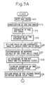
- step S14 n times of expanding operations are carried out on the ROI image, and in step S16, (n+1) times of contracting operations are carried out on the expanded image.
- step S18 a filling hole operation is carried out on the contracted image to provide a first solid image.
- step S20 boundary pixels of the first solid image which bounds the background pixels are determined and extracted from the first solid image.
- step S22 the pixels which belongs to the boundary pixels or the ROI image are extracted, which is referred to as an OR operation between the boundary pixels and the ROI image. This results in a subject binary image, in which openings in the cortical bone portion are closed by the boundary pixels.
- step S24 a thinning operation is carried out on the subject binary image to obtain a thinned image as shown in Figure 8A.
- the thinned image includes a series of pixels which are substantially along the center line of the cortical bone portion.
- step S26 a filling hole operation is carried out on the thinned image to obtain a second solid image.
- step S28 one contracting operation is carried out on the second solid image, and in step S30, one expanding operation is carried out on the contracted second solid image to eliminate noise pixels from the second solid image, which is referred to as a subject solid image.
- step 32 a NAND operation is carried out to extract pixels which are not common to the subject solid image and the subject binary image so that an image (in Figure 8C) which has a wall thickness substantially half of the real cortical bone portion is provided by the extracted common pixels.
- the image composed of the extracted pixels is referred to a hemi-cortical bone image in this specification.
- step S36 expanding operations are carried out by a predetermined number of times on the hemi-cortical image to provide a template image for the cortical bone portion as shown in Figure 8D.
- the number of times for carrying out the expansion is preferably defined by INT(MWT ⁇ ⁇ + 1).
- the number of times for carrying out the expansion may be defined by INT(MWT ⁇ ⁇ + 1.5).
- a number 1.0 ⁇ ⁇ ⁇ 2.0 can be selected advantageously.
- step S38 an AND operation is carried out between the ROI image and the template image for the cortical bone portion to separate or to extract an image of the cortical bone portion ( Figure 8E) from the ROI image.
- step S40 a NAND operation is carried out between the ROI image and the separated cortical bone image to separate or to extract an image of the cancellous bone.
- a NAND operation can be carried out between the template image for the cortical bone and the ROI image to provide the cancellous bone image. Removing the cancellous bone image from the ROI image provides the cortical bone image.
- a semi-binary image can be provided by putting the intensity values of the original bone sectional image obtained by the micro-focus X-ray computed tomography on the respective pixels of the cortical bone image and/or the cancellous bone image, and putting zero (0) value on the remaining background pixels.
- the hole of the sectional image can be defined as ROI image.
- the section of a sample bone has a relatively simple configuration as in the previous description regarding a femur
- the hole of the sectional image can be defined as ROI image.
- a portion of the sectional image must be defined as ROI image onto which an analysis is carried out.
- ROI is defined through providing a subject region for analysis on the sectional image.
- a bone sectional image is input in the image processing system as a raw image.
- a sectional image of a vertebral body of a rat which is obtained by micro-focus X-ray computed tomography is used.
- the input raw image is binarized or digitized to provide a binary image of a bone section as described above.
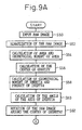
- step S54 the area of the binary image (AMB) is calculated by the following equation.
- AMB ⁇ i ⁇ j ⁇ [p(i,j)]
- step S54 the geometrical moment of area is calculated by the following equations.
- M x1 ⁇ i ⁇ j j ⁇ [p(i,j)]
- M y1 ⁇ i ⁇ j i ⁇ [p(i,j)]
- step S56 the center of gravity G of the binary image is calculated by the following equation.
- (X g , Y g ) (M x1 /AMB, M y1 /AMB)
- step S58 the geometrical moment of inertia of the binary image is calculated by the following equations.
- M x2 ⁇ i ⁇ j (j - Y g ) 2 ⁇ [p(i,j)]
- M y2 ⁇ i ⁇ j (i - X g ) 2 ⁇ [p(i,j)]
- step S58 the product of inertia is calculated by the following equation.
- M 11 ⁇ i ⁇ j (i - X g ) ⁇ (j - Y g ) ⁇ [p(i,j)]
- step S60 calculated by the following equation is the angle ⁇ , related to the X-axis, of the axis of inertia about the center of gravity of the bone portion.
- ⁇ (tan -1 (2 x M 11 /(M x2 - M y2 )))/2
- step S62 the input raw image is rotated around the center of gravity by (90 - ⁇ ) degrees in the clockwise direction so that the axis of inertia is parallel to Y-axis.
- step S64 the rotated raw image is binarized or digitized by the process described above.
- step S66 pixels corresponding to the vertebral canal in the rotated binary image is determined as described below.
- the rotated binary image of a vertebral body of a rat processed as described above is shown.
- the vertebral canal 50 is the largest hole in the sectional bone image.
- the areas of the respective holes are calculated by the following equation.
- ⁇ h [p(i,j)] 0 (if pixel (i,j) belongs to class 1 which does not indicate a hole)
- step S68 determined is a pair of fillet coordinates F 1 (x 1 , y 1 ) and F 2 (x 2 , Y 2 ) which are at the corners on one of the diagonals of the smallest rectangle enclosing the vertebral canal.
- the fillet coordinates F 1 and F 2 can be defined as follows.
- step S70 distances d 1 and d 2 are calculated between the axis of inertia and the fillet coordinates F 1 (x 1 , y 1 ) and F 2 (x 2 , Y 2 ), respectively.
- the constant value ⁇ can be optionally determined to eliminate unwanted bone portions, such as anapophysises, which do not substantially contribute to the bone strength.
- ⁇ 0.9 is selected in consideration of the general configuration of a vertebral body of a rat.
- Another value of ⁇ can be advantageously employed depending on the general configuration in a sectional image of a kind of a bone.
- a subject region for analysis is defined automatically by using the representative length L r so that the previously mentioned prior art human error is eliminated.
- a subject region for analysis is defined by a rectangle 52 which has a pair of diagonal coordinates (X g - d 3 , Y g ) and (X g + d 3 , 479).
- a ROI is defined within the subject region to provide a ROI image by the pixels corresponding to the bone portion within the subject region as shown in Figure 11.
- step S76 n times of expanding operations are carried out on the ROI image, then in step S78, (n+1) times of contracting operations are carried out on the expanded image.
- step S80 a filling hole operation is carried out on the contracted image to provide a solid image.
- step S82 boundary pixels of the solid image which contact the background pixels are determined, and are extracted from the solid image.
- step S84 an OR operation between the boundary pixels and the ROI image are executed to provide a subject binary image, in which openings in the cortical bone portion are closed by the boundary pixels.
- step S86 a thinning operation is carried out on the subject binary image to obtain a thinned image.
- the thinned image includes a series of pixels which are substantially along the center line of the cortical bone portion.
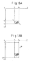
- step S88 an AND operation is carried out between the thinned image and the ROI image to provide a thinned subject image shown in Figure 12A.
- step S90 a pair of fillet coordinates F 3 (x 3 , y 3 ) and F 4 (x 4 , y 4 ), which are at the corners on one of the diagonals of the smallest rectangle enclosing the thinned subject image, are determined.
- the fillet coordinates F3(x3, y3) and F4(x4, y4) can be defined as follows.
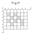
- a rectangle operation area 56 which has a pair of fillet coordinates F oa1 (x 3 , 1), F oa2 (x 4 , 478) is provided as shown in Figure 12B.
- the rectangle operation area 56 includes the largest and second largest holes or backgrounds 58 and 60 which have the background intensity, 0 (zero), in this embodiment at the upper and lower sides which bounds the pixels of the thinned subject image corresponding to the center line extending along the cortical bone portion.
- step S94 a find hole operation, which determines holes which have the background intensity is carried out within the operation area 56, and the respective holes are labeled.
- step S96 the largest and the second largest backgrounds 58 and 60, which are labeled in step S94, are determined in the operation area 56 as shown in Figure 12C.
- step S98 the pixels which are common to the largest background image and the subject binary image (AND operation) to provide a first hemi-cortical image 62 shown in Figure 12D, which has a wall thickness substantially half of the corresponding portion of the real cortical bone.
- an AND operation is carried out between the second largest background image and the subject binary image to provide a second hemi-cortical image 64.
- step S100 the mean wall thickness (MWT 1 and MWT 2 ) of the first and second hemi-cortical images 62 and 64 is calculated, respectively as described above.
- Figure 12D shows a hemi-cortical bone image combined by the first and second hemi-cortical bone images 62 and 64.
- step S102 expanding operations are carried out on the hemi-cortical image to provide a template image for the cortical bone portion as shown in Figure 12E.
- the first hemi-cortical bone image 62 is expanded n 1 times
- the second hemi-cortical bone image 64 is expanded n 2 times.
- n 2 INT(MWT 2 x ⁇ 2 + 1)
- step S104 an AND operation is carried out between the template image and the ROI image to extract pixels corresponding to the cortical bone portion shown in Figure 12F.
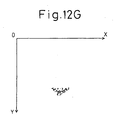
- step S106 a NAND operation is carried out between the template image and the ROI image to extract pixels corresponding to the cancellous bone portion shown in Figure 12G.
- the cancellous bone portion and the cortical bone portion are extracted from the binary image of a sample bone section through providing the hemi-cortical bone image and the template image for the cortical bone portion. This provides significant improvement in precision of the separation of the cortical bone portion and the cancellous bone portion compared with the prior art.
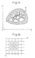
- Various measurements and analyses are carried out on the ROI image thus provided. For example, measurement of numbers of the terminuses, the struts and the nodes, and measurement of the length of the struts of the bone portion (shown by fine lines in Figure 13) can be carried out after the ROI image is further processed by a thinning operation.
- Figure 14 schematically illustrates a measurement of the length of an intercept between a line and the bone portion.
- a line 56 which extends at an angle relative to the X-axis through point P which is selected at random, intersects the cancellous bone portion at three intercepts 56a, 56b and 56c.
- the respective lengths of the intercepts 56a, 56b and 56c are determined.
- This process is repeated by a statistically sufficient number of times with the position of the point P and the angle of the line 56 being changed at random. For example, the position of the point P is changed by one hundred times and the angle of the line 56 is changed by thirty-six times at the respective positions of the point P.
- This measurement can be applied to the cortical bone portion and to the marrow space portion.
- the sample of the length of the intercepts measured as described above may be processed to provide mean, maximum and minimum length, standard deviation of length and/or a parameter provided by combination thereof.
- the sample may be analyzed by using a pattern analysis such as Fourier analysis.
- the measurement and analysis can include a tensor analysis of the cancellous bone portion as described hereinafter.
- the tensor analysis is weighted by the mean wall thickness (MWT) of the cancellous bone portion.
- the structural anisotropy of the cancellous bone portion is determined by a tensor analysis as described bellow.
- the binary image corresponding to the cancellous bone portion provided by the invention is processed to provide a thinned image. The following operation is carried out on the each pixel of the thinned image.
- Figure 16 illustrates a flow chart for determining the structural anisotropy of the cancellous bone portion according to the invention.
- step S110 in Figure 16 an initialization is carried out so that zero (0) is input into adjacency parameters n 0 to n 7 which associate to the adjacent pixels P 0 to P 7 , respectively.
- the adjacency parameters n i , i 1, 2, 3, 5, 6 and 7, are associated in the Y orientation relative to the pixel of interest P ior .
- step S112 zero (0) is input into parameter i.
- step S114 it is determined whether the adjacent pixel P i indicates the bone portion or not. If so, one (1) is added to the parameter n i (step S116), and the routine goes to step S118.
- step S114 if the adjacent pixel P i does not indicate the bone portion, the routine also goes to step S118.
- NN X (MWT ⁇ N X )/(N X 2 + N Y 2 ) 1/2
- NN Y (MWT ⁇ N Y )/(N X 2 + N Y 2 ) 1/2
- the relative tensor indicates the relative strength of the cancellous bone portion as well as the degree of the structural anisotropy of the cancellous bone portion. That is, by consideration of MWT, the length of the relative tensor (NN X , NN Y ) indicates the relative strength of the cancellous bone portion, and the ratio of NN X and NN Y indicates the structural anisotropy of the cancellous bone portion.
Landscapes
- Engineering & Computer Science (AREA)
- Physics & Mathematics (AREA)
- Computer Vision & Pattern Recognition (AREA)
- General Physics & Mathematics (AREA)
- Theoretical Computer Science (AREA)
- Geometry (AREA)
- Health & Medical Sciences (AREA)
- General Health & Medical Sciences (AREA)
- Medical Informatics (AREA)
- Nuclear Medicine, Radiotherapy & Molecular Imaging (AREA)
- Radiology & Medical Imaging (AREA)
- Quality & Reliability (AREA)
- Apparatus For Radiation Diagnosis (AREA)
- Image Processing (AREA)
- Analysing Materials By The Use Of Radiation (AREA)
Claims (22)
- Procédé de traitement d'une image d'os en coupe pour la morphométrie d'un os qui comprend une partie d'os cortical et une partie d'os spongieux, comprenant les étapes consistant à :entrer une image binaire d'une coupe d'os dans un système de traitement d'image ;fournir une région sujet sur l'image binaire pour produire une image de région d'intérêt en extrayant les pixels correspondant à la partie d'os de l'image binaire dans la région sujet, image de région d'intérêt sur laquelle la morphométrie est conduite ;déterminer une série de pixels le long de la ligne centrale s'étendant le long de la partie d'os cortical dans l'image de région d'intérêt ;fournir une image d'os hémicortical qui a une épaisseur de paroi sensiblement égale à la moitié de l'épaisseur de paroi réelle de la partie d'os cortical en utilisant la ligne centrale déterminée dans l'étape précédente ;fournir une image modèle de la partie d'os cortical en exécutant des opérations d'agrandissement sur l'image d'os hémicortical un nombre de fois prédéterminé ;éliminer les pixels, qui sont communs à l'image de région d'intérêt et l'image modèle, de l'image de région d'intérêt pour fournir une image correspondant à la partie d'os spongieux ;éliminer l'image correspondant à la partie d'os spongieux de l'image de région d'intérêt pour fournir une image correspondant à la partie d'os cortical ; etexécuter une analyse tensorielle sur l'image correspondant à l'os spongieux pour déterminer l'anisotropie structurelle dans l'os spongieux.
- Procédé de traitement d'une image d'os en coupe pour la morphométrie d'un os qui comprend une partie d'os cortical et une partie d'os spongieux, comprenant les étapes consistant à :entrer une image binaire d'une coupe d'os dans un système de traitement d'image ;fournir une région sujet sur l'image binaire pour produire une image de région d'intérêt en extrayant les pixels correspondant à la partie d'os de l'image binaire dans la région sujet, image de région d'intérêt sur laquelle la morphométrie est conduite ;déterminer une série de pixels le long de la ligne centrale s'étendant le long de la partie d'os cortical dans l'image de région d'intérêt ;fournir une image d'os hémicortical qui a une épaisseur de paroi sensiblement égale à la moitié de l'épaisseur de paroi réelle de la partie d'os cortical en utilisant la ligne centrale déterminée dans l'étape précédente ;fournir une image modèle de la partie d'os cortical en exécutant des opérations d'agrandissement sur l'image d'os hémicortical un nombre de fois prédéterminé ;extraire les pixels communs entre l'image de région d'intérêt et l'image modèle pour fournir une image correspondant à la partie d'os cortical ;éliminer l'image correspondant à la partie d'os cortical de l'image de région d'intérêt pour fournir une image correspondant à la partie d'os spongieux ; etexécuter une analyse tensorielle sur l'image correspondant à l'os spongieux pour déterminer l'anisotropie structurelle dans l'os spongieux.
- Procédé de traitement d'une image d'os en coupe selon la revendication 1, dans lequel la série de pixels le long de la ligne centrale s'étendant le long de la partie d'os cortical est déterminée en exécutant un processus d'affinement sur l'image de région d'intérêt.
- Procédé de traitement d'une image d'os en coupe selon la revendication 1, dans lequel l'image d'os hémicortical est fournie par les étapes consistant à :exécuter une opération de remplissage de trou sur l'image de ligne centrale pour fournir une image pleine ; etenlever les pixels de l'image pleine de l'image de région d'intérêt.
- Procédé de traitement d'une image d'os en coupe selon la revendication 1, comprenant de plus une étape consistant à extraire les pixels communs entre l'image de région d'intérêt et l'image modèle pour fournir une image correspondant sensiblement à la partie d'os cortical.
- Procédé de traitement d'une image d'os en coupe selon la revendication 5, comprenant de plus une étape consistant à éliminer l'image correspondant à l'image d'os cortical de l'image de région d'intérêt pour fournir une image correspondant à la partie d'os spongieux.
- Procédé de traitement d'une image d'os en coupe selon la revendication 6, comprenant de plus l'étape consistant à exécuter une analyse tensorielle sur l'image correspondant à l'os spongieux pour déterminer l'anisotropie structurelle dans l'os spongieux.
- Procédé de traitement d'une image d'os en coupe selon la revendication 2, comprenant de plus une étape consistant à éliminer les pixels, qui sont communs à l'image de région d'intérêt et l'image modèle, de l'image de région d'intérêt pour fournir une image correspondant à la partie d'os spongieux.
- Procédé de traitement d'une image d'os en coupe selon la revendication 8, comprenant de plus une étape consistant à éliminer l'image correspondant à la partie d'os spongieux de l'image de région d'intérêt pour fournir une image correspondant à la partie d'os cortical.
- Procédé de traitement d'une image d'os en coupe selon la revendication 8 ou 9, comprenant de plus l'étape consistant à exécuter une analyse tensorielle sur l'image correspondant à l'os spongieux pour déterminer l'anisotropie structurelle dans l'os spongieux.
- Procédé de traitement d'une image d'os en coupe selon la revendication 1, dans lequel l'image binaire est celle d'un corps vertébral qui comprend une partie d'os cortical et une partie d'os spongieux, et la région d'intérêt est fournie par les étapes consistant à :déterminer l'axe d'inertie de l'image binaire d'un corps vertébral ;déterminer les pixels correspondant au canal vertébral dans l'image binaire d'un corps vertébral ;déterminer une longueur respective relative à l'extension du canal vertébral ; etfournir une région sujet sur l'image binaire sur la base de la longueur représentative pour extraire les pixels correspondant à la partie d'os dans la région sujet de telle manière que la région d'intérêt soit définie sur l'image binaire par les pixels extraits.
- Procédé de traitement d'une image d'os en coupe selon la revendication 11, dans lequel l'étape de détermination de la longueur représentative comprend les étapes consistant à fournir le plus petit rectangle contenant les pixels du canal vertébral ;
déterminer une paire de coordonnées de coin qui sont aux coins sur une des diagonales du plus petit rectangle contenant le canal vertébral ; et
déterminer les distances entre l'axe d'inertie et les coordonnées de coin en tant que longueur représentative. - Procédé de traitement d'une image d'os en coupe selon la revendication 11, dans lequel l'étape consistant à déterminer la longueur représentative comprend les étapes consistant à déterminer les coordonnées x et y maximales et minimales des pixels qui appartiennent au canal vertébral ; et
déterminer les distances entre l'axe d'inertie et les points définis par les coordonnées x et y maximales et minimales en tant que longueur représentative. - Procédé de traitement d'une image d'os en coupe selon la revendication 11, comprenant de plus l'étape consistant à fournir une image modèle de la partie d'os cortical en exécutant des opérations d'agrandissement sur l'image d'os hémicortical un nombre de fois prédéterminé.
- Procédé de traitement d'une image d'os en coupe selon la revendication 11, dans lequel une série de pixels le long de la ligne centrale s'étendant le long de la partie d'os cortical est déterminée en exécutant un processus d'affinement sur l'image de région d'intérêt.
- Procédé de traitement d'une image d'os en coupe selon la revendication 11, dans lequel l'image d'os hémicortical est fournie par les étapes consistant à :fournir une région d'opération pour contenir l'image de région d'intérêt de sorte que la région d'opération comprenant les plus grande et deuxième plus grande parties d'arrière-plan de chaque côté de l'image de région d'intérêt soit liée aux pixels de ligne centrale ;déterminer les plus grande et deuxième plus grande parties d'arrière-plan dans la région d'opération ;déterminer des premiers pixels qui sont communs à la plus grande image de trou et l'image de région d'intérêt pour fournir une première image d'os hémicortical ;déterminer des deuxièmes pixels qui sont communs à la plus grande image de trou et l'image de région d'intérêt pour fournir une deuxième image d'os hémicortical ; etcombiner les première et deuxième images d'os hémicortical pour fournir l'image d'os hémicortical.
- Procédé de traitement d'une image d'os en coupe selon la revendication 11, comprenant de plus une étape consistant à extraire les pixels communs entre l'image de région d'intérêt et l'image modèle pour fournir une image correspondant sensiblement à la partie d'os cortical.
- Procédé de traitement d'une image d'os en coupe selon la revendication 17, comprenant de plus une étape consistant à éliminer l'image correspondant à l'image d'os cortical de l'image de région d'intérêt pour fournir une image correspondant à la partie d'os spongieux.
- Procédé de traitement d'une image d'os en coupe selon la revendication 18, comprenant de plus l'étape consistant à exécuter une analyse tensorielle sur l'image correspondant à l'os spongieux pour déterminer l'anisotropie structurelle dans l'os spongieux.
- Procédé de traitement d'une image d'os en coupe selon la revendication 11, comprenant de plus une étape consistant à éliminer les pixels, qui sont communs à l'image de région d'intérêt et l'image modèle, de l'image de région d'intérêt pour fournir une image correspondant à la partie d'os spongieux.
- Procédé de traitement d'une image d'os en coupe selon la revendication 20, comprenant de plus une étape consistant à éliminer l'image correspondant à la partie d'os spongieux de l'image de région d'intérêt pour fournir une image correspondant à la partie d'os cortical.
- Procédé de traitement d'une image d'os en coupe selon la revendication 20, comprenant de plus l'étape consistant à exécuter une analyse tensorielle sur l'image correspondant à l'os spongieux pour déterminer l'anisotropie structurelle dans l'os spongieux.
Applications Claiming Priority (9)
| Application Number | Priority Date | Filing Date | Title |
|---|---|---|---|
| JP07643096A JP3258233B2 (ja) | 1996-03-29 | 1996-03-29 | 骨計測方法 |
| JP76430/96 | 1996-03-29 | ||
| JP7643096 | 1996-03-29 | ||
| JP08394096A JP3238626B2 (ja) | 1996-04-05 | 1996-04-05 | 骨計測方法 |
| JP8394096 | 1996-04-05 | ||
| JP83940/96 | 1996-04-05 | ||
| JP112418/96 | 1996-05-07 | ||
| JP11241896A JP3229200B2 (ja) | 1996-05-07 | 1996-05-07 | 骨計測方法 |
| JP11241896 | 1996-05-07 |
Publications (3)
| Publication Number | Publication Date |
|---|---|
| EP0803843A2 EP0803843A2 (fr) | 1997-10-29 |
| EP0803843A3 EP0803843A3 (fr) | 1997-11-12 |
| EP0803843B1 true EP0803843B1 (fr) | 2003-09-17 |
Family
ID=27302154
Family Applications (1)
| Application Number | Title | Priority Date | Filing Date |
|---|---|---|---|
| EP97105299A Expired - Lifetime EP0803843B1 (fr) | 1996-03-29 | 1997-03-27 | Appareil pour le traitement d'images en coupe d'échantillons osseux comprenant des parties corticales et spongieuses |
Country Status (6)
| Country | Link |
|---|---|
| US (1) | US5835619A (fr) |
| EP (1) | EP0803843B1 (fr) |
| AT (1) | ATE250252T1 (fr) |
| AU (1) | AU713136B2 (fr) |
| CA (1) | CA2201057C (fr) |
| DE (1) | DE69724865D1 (fr) |
Cited By (1)
| Publication number | Priority date | Publication date | Assignee | Title |
|---|---|---|---|---|
| DE102004026524A1 (de) * | 2004-05-25 | 2005-12-22 | Aesculap Ag & Co. Kg | Verfahren zur Bestimmung eines knocheneigenen Koordinatensystems |
Families Citing this family (123)
| Publication number | Priority date | Publication date | Assignee | Title |
|---|---|---|---|---|
| US6021213A (en) * | 1996-06-13 | 2000-02-01 | Eli Lilly And Company | Automatic contextual segmentation for imaging bones for osteoporosis therapies |
| US7618451B2 (en) | 2001-05-25 | 2009-11-17 | Conformis, Inc. | Patient selectable joint arthroplasty devices and surgical tools facilitating increased accuracy, speed and simplicity in performing total and partial joint arthroplasty |
| US8556983B2 (en) | 2001-05-25 | 2013-10-15 | Conformis, Inc. | Patient-adapted and improved orthopedic implants, designs and related tools |
| US8480754B2 (en) | 2001-05-25 | 2013-07-09 | Conformis, Inc. | Patient-adapted and improved articular implants, designs and related guide tools |
| US8545569B2 (en) | 2001-05-25 | 2013-10-01 | Conformis, Inc. | Patient selectable knee arthroplasty devices |
| US8735773B2 (en) | 2007-02-14 | 2014-05-27 | Conformis, Inc. | Implant device and method for manufacture |
| US7534263B2 (en) | 2001-05-25 | 2009-05-19 | Conformis, Inc. | Surgical tools facilitating increased accuracy, speed and simplicity in performing joint arthroplasty |
| US8771365B2 (en) | 2009-02-25 | 2014-07-08 | Conformis, Inc. | Patient-adapted and improved orthopedic implants, designs, and related tools |
| US9603711B2 (en) | 2001-05-25 | 2017-03-28 | Conformis, Inc. | Patient-adapted and improved articular implants, designs and related guide tools |
| US7468075B2 (en) | 2001-05-25 | 2008-12-23 | Conformis, Inc. | Methods and compositions for articular repair |
| US8882847B2 (en) | 2001-05-25 | 2014-11-11 | Conformis, Inc. | Patient selectable knee joint arthroplasty devices |
| US8083745B2 (en) | 2001-05-25 | 2011-12-27 | Conformis, Inc. | Surgical tools for arthroplasty |
| JP3656695B2 (ja) * | 1997-09-30 | 2005-06-08 | 富士写真フイルム株式会社 | 骨計測方法および装置 |
| US6310967B1 (en) * | 1998-04-29 | 2001-10-30 | University Of South Florida | Normal and abnormal tissue identification system and method for medical images such as digital mammograms |
| US7184814B2 (en) | 1998-09-14 | 2007-02-27 | The Board Of Trustees Of The Leland Stanford Junior University | Assessing the condition of a joint and assessing cartilage loss |
| ATE439806T1 (de) | 1998-09-14 | 2009-09-15 | Univ Leland Stanford Junior | Zustandsbestimmung eines gelenks und schadenvorsorge |
| US7239908B1 (en) | 1998-09-14 | 2007-07-03 | The Board Of Trustees Of The Leland Stanford Junior University | Assessing the condition of a joint and devising treatment |
| US6839457B1 (en) | 1999-06-03 | 2005-01-04 | Teijin Limited | Bone measuring method |
| US6941323B1 (en) * | 1999-08-09 | 2005-09-06 | Almen Laboratories, Inc. | System and method for image comparison and retrieval by enhancing, defining, and parameterizing objects in images |
| AU9088801A (en) | 2000-09-14 | 2002-03-26 | Univ Leland Stanford Junior | Assessing the condition of a joint and devising treatment |
| KR100419573B1 (ko) * | 2000-12-14 | 2004-02-19 | 한국전자통신연구원 | 엑스선 영상을 이용한 해면골 발달정도 측정 방법 |
| US7664297B2 (en) * | 2001-04-26 | 2010-02-16 | Teijin Limited | Three-dimensional joint structure measuring method |
| US8439926B2 (en) | 2001-05-25 | 2013-05-14 | Conformis, Inc. | Patient selectable joint arthroplasty devices and surgical tools |
| DE60239674D1 (de) | 2001-05-25 | 2011-05-19 | Conformis Inc | Verfahren und zusammensetzungen zur reparatur der oberfläche von gelenken |
| US20030133601A1 (en) * | 2001-11-23 | 2003-07-17 | University Of Chicago | Automated method and system for the differentiation of bone disease on radiographic images |
| ITMI20021184A1 (it) * | 2002-05-31 | 2003-12-01 | Milano Politecnico | Dispositivo per la misura del tensore di un corpo rigido |
| AU2003284035A1 (en) | 2002-10-07 | 2004-05-04 | Conformis, Inc. | Minimally invasive joint implant with 3-dimensional geometry matching the articular surfaces |
| EP3075356B1 (fr) | 2002-11-07 | 2023-07-05 | ConforMIS, Inc. | Méthode de sélection d'un implant méniscal |
| WO2006039358A2 (fr) * | 2004-09-30 | 2006-04-13 | The Regents Of The University Of California | Methode d'evaluation de caracteristiques de structure-fonction de structures dans un corps humain ou animal |
| EP1847221B1 (fr) * | 2005-02-09 | 2013-07-17 | Hitachi Medical Corporation | Systeme support d'imagerie de diagnostic et programme support correspondant |
| US8623026B2 (en) | 2006-02-06 | 2014-01-07 | Conformis, Inc. | Patient selectable joint arthroplasty devices and surgical tools incorporating anatomical relief |
| EP2649951A3 (fr) | 2006-02-06 | 2013-12-25 | ConforMIS, Inc. | Dispositifs d'arthroplastie articulaire et outils chirurgicaux selectionnables par le patient |
| US9345548B2 (en) | 2006-02-27 | 2016-05-24 | Biomet Manufacturing, Llc | Patient-specific pre-operative planning |
| US8407067B2 (en) | 2007-04-17 | 2013-03-26 | Biomet Manufacturing Corp. | Method and apparatus for manufacturing an implant |
| US9289253B2 (en) | 2006-02-27 | 2016-03-22 | Biomet Manufacturing, Llc | Patient-specific shoulder guide |
| US8608748B2 (en) | 2006-02-27 | 2013-12-17 | Biomet Manufacturing, Llc | Patient specific guides |
| US9918740B2 (en) | 2006-02-27 | 2018-03-20 | Biomet Manufacturing, Llc | Backup surgical instrument system and method |
| US8133234B2 (en) | 2006-02-27 | 2012-03-13 | Biomet Manufacturing Corp. | Patient specific acetabular guide and method |
| US8568487B2 (en) | 2006-02-27 | 2013-10-29 | Biomet Manufacturing, Llc | Patient-specific hip joint devices |
| US9173661B2 (en) | 2006-02-27 | 2015-11-03 | Biomet Manufacturing, Llc | Patient specific alignment guide with cutting surface and laser indicator |
| US9113971B2 (en) | 2006-02-27 | 2015-08-25 | Biomet Manufacturing, Llc | Femoral acetabular impingement guide |
| US20150335438A1 (en) | 2006-02-27 | 2015-11-26 | Biomet Manufacturing, Llc. | Patient-specific augments |
| US7967868B2 (en) | 2007-04-17 | 2011-06-28 | Biomet Manufacturing Corp. | Patient-modified implant and associated method |
| US8535387B2 (en) | 2006-02-27 | 2013-09-17 | Biomet Manufacturing, Llc | Patient-specific tools and implants |
| US8603180B2 (en) | 2006-02-27 | 2013-12-10 | Biomet Manufacturing, Llc | Patient-specific acetabular alignment guides |
| US10278711B2 (en) | 2006-02-27 | 2019-05-07 | Biomet Manufacturing, Llc | Patient-specific femoral guide |
| US8377066B2 (en) * | 2006-02-27 | 2013-02-19 | Biomet Manufacturing Corp. | Patient-specific elbow guides and associated methods |
| US9907659B2 (en) | 2007-04-17 | 2018-03-06 | Biomet Manufacturing, Llc | Method and apparatus for manufacturing an implant |
| US9339278B2 (en) | 2006-02-27 | 2016-05-17 | Biomet Manufacturing, Llc | Patient-specific acetabular guides and associated instruments |
| US8591516B2 (en) | 2006-02-27 | 2013-11-26 | Biomet Manufacturing, Llc | Patient-specific orthopedic instruments |
| US8608749B2 (en) | 2006-02-27 | 2013-12-17 | Biomet Manufacturing, Llc | Patient-specific acetabular guides and associated instruments |
| US20070211930A1 (en) * | 2006-03-09 | 2007-09-13 | Terry Dolwick | Attribute based image enhancement and display for medical imaging applications |
| WO2007122783A1 (fr) * | 2006-04-13 | 2007-11-01 | Kansai Technology Licensing Organization Co., Ltd. | procédé de fabrication d'os artificiel |
| US9795399B2 (en) | 2006-06-09 | 2017-10-24 | Biomet Manufacturing, Llc | Patient-specific knee alignment guide and associated method |
| GB2442441B (en) | 2006-10-03 | 2011-11-09 | Biomet Uk Ltd | Surgical instrument |
| WO2008101090A2 (fr) | 2007-02-14 | 2008-08-21 | Conformis, Inc. | Dispositif d'implant et procédé de fabrication |
| WO2008157412A2 (fr) | 2007-06-13 | 2008-12-24 | Conformis, Inc. | Guide d'incision chirurgical |
| US20090055137A1 (en) * | 2007-08-22 | 2009-02-26 | Imed Gargouri | Method for obtaining geometric properties of an anatomic part |
| US8682052B2 (en) | 2008-03-05 | 2014-03-25 | Conformis, Inc. | Implants for altering wear patterns of articular surfaces |
| JP4492886B2 (ja) * | 2008-04-03 | 2010-06-30 | 富士フイルム株式会社 | 3次元腹腔内領域検出装置、方法、およびプログラム |
| AU2009246474B2 (en) | 2008-05-12 | 2015-04-16 | Conformis, Inc. | Devices and methods for treatment of facet and other joints |
| US8808297B2 (en) | 2009-02-24 | 2014-08-19 | Microport Orthopedics Holdings Inc. | Orthopedic surgical guide |
| US8808303B2 (en) | 2009-02-24 | 2014-08-19 | Microport Orthopedics Holdings Inc. | Orthopedic surgical guide |
| EP2405865B1 (fr) | 2009-02-24 | 2019-04-17 | ConforMIS, Inc. | Systèmes automatisés four la fabrication des implants et instruments adaptés individuellement au patient |
| US9017334B2 (en) | 2009-02-24 | 2015-04-28 | Microport Orthopedics Holdings Inc. | Patient specific surgical guide locator and mount |
| US12383287B2 (en) | 2009-02-24 | 2025-08-12 | Microport Orthopedics Holdings, Inc. | Systems and methods for installing an orthopedic implant |
| SG175229A1 (en) | 2009-04-16 | 2011-11-28 | Conformis Inc | Patient-specific joint arthroplasty devices for ligament repair |
| DE102009028503B4 (de) | 2009-08-13 | 2013-11-14 | Biomet Manufacturing Corp. | Resektionsschablone zur Resektion von Knochen, Verfahren zur Herstellung einer solchen Resektionsschablone und Operationsset zur Durchführung von Kniegelenk-Operationen |
| AU2010327987B2 (en) | 2009-12-11 | 2015-04-02 | Conformis, Inc. | Patient-specific and patient-engineered orthopedic implants |
| US9058665B2 (en) * | 2009-12-30 | 2015-06-16 | General Electric Company | Systems and methods for identifying bone marrow in medical images |
| US8632547B2 (en) | 2010-02-26 | 2014-01-21 | Biomet Sports Medicine, Llc | Patient-specific osteotomy devices and methods |
| US9271744B2 (en) | 2010-09-29 | 2016-03-01 | Biomet Manufacturing, Llc | Patient-specific guide for partial acetabular socket replacement |
| US9968376B2 (en) | 2010-11-29 | 2018-05-15 | Biomet Manufacturing, Llc | Patient-specific orthopedic instruments |
| SG193484A1 (en) | 2011-02-15 | 2013-10-30 | Conformis Inc | Patent-adapted and improved articular implants, designs, surgical procedures and related guide tools |
| US9241745B2 (en) | 2011-03-07 | 2016-01-26 | Biomet Manufacturing, Llc | Patient-specific femoral version guide |
| US8715289B2 (en) | 2011-04-15 | 2014-05-06 | Biomet Manufacturing, Llc | Patient-specific numerically controlled instrument |
| US9675400B2 (en) | 2011-04-19 | 2017-06-13 | Biomet Manufacturing, Llc | Patient-specific fracture fixation instrumentation and method |
| US8668700B2 (en) | 2011-04-29 | 2014-03-11 | Biomet Manufacturing, Llc | Patient-specific convertible guides |
| US8956364B2 (en) | 2011-04-29 | 2015-02-17 | Biomet Manufacturing, Llc | Patient-specific partial knee guides and other instruments |
| US8532807B2 (en) | 2011-06-06 | 2013-09-10 | Biomet Manufacturing, Llc | Pre-operative planning and manufacturing method for orthopedic procedure |
| US9084618B2 (en) | 2011-06-13 | 2015-07-21 | Biomet Manufacturing, Llc | Drill guides for confirming alignment of patient-specific alignment guides |
| US8891848B2 (en) * | 2011-06-14 | 2014-11-18 | Radnostics, LLC | Automated vertebral body image segmentation for medical screening |
| US20130001121A1 (en) | 2011-07-01 | 2013-01-03 | Biomet Manufacturing Corp. | Backup kit for a patient-specific arthroplasty kit assembly |
| US8764760B2 (en) | 2011-07-01 | 2014-07-01 | Biomet Manufacturing, Llc | Patient-specific bone-cutting guidance instruments and methods |
| US8597365B2 (en) | 2011-08-04 | 2013-12-03 | Biomet Manufacturing, Llc | Patient-specific pelvic implants for acetabular reconstruction |
| WO2013020143A1 (fr) * | 2011-08-04 | 2013-02-07 | University Of Southern California | Quantification de fissures basée sur des images |
| US9295497B2 (en) | 2011-08-31 | 2016-03-29 | Biomet Manufacturing, Llc | Patient-specific sacroiliac and pedicle guides |
| US9066734B2 (en) | 2011-08-31 | 2015-06-30 | Biomet Manufacturing, Llc | Patient-specific sacroiliac guides and associated methods |
| US9386993B2 (en) | 2011-09-29 | 2016-07-12 | Biomet Manufacturing, Llc | Patient-specific femoroacetabular impingement instruments and methods |
| US9554910B2 (en) | 2011-10-27 | 2017-01-31 | Biomet Manufacturing, Llc | Patient-specific glenoid guide and implants |
| US9301812B2 (en) | 2011-10-27 | 2016-04-05 | Biomet Manufacturing, Llc | Methods for patient-specific shoulder arthroplasty |
| ES2635542T3 (es) | 2011-10-27 | 2017-10-04 | Biomet Manufacturing, Llc | Guías glenoideas específicas para el paciente |
| US9451973B2 (en) | 2011-10-27 | 2016-09-27 | Biomet Manufacturing, Llc | Patient specific glenoid guide |
| KR20130046336A (ko) | 2011-10-27 | 2013-05-07 | 삼성전자주식회사 | 디스플레이장치의 멀티뷰 디바이스 및 그 제어방법과, 디스플레이 시스템 |
| WO2013090830A1 (fr) | 2011-12-16 | 2013-06-20 | University Of Southern California | Évaluation autonome d'état de chaussée |
| US9237950B2 (en) | 2012-02-02 | 2016-01-19 | Biomet Manufacturing, Llc | Implant with patient-specific porous structure |
| US9486226B2 (en) | 2012-04-18 | 2016-11-08 | Conformis, Inc. | Tibial guides, tools, and techniques for resecting the tibial plateau |
| US9675471B2 (en) | 2012-06-11 | 2017-06-13 | Conformis, Inc. | Devices, techniques and methods for assessing joint spacing, balancing soft tissues and obtaining desired kinematics for joint implant components |
| US9204977B2 (en) | 2012-12-11 | 2015-12-08 | Biomet Manufacturing, Llc | Patient-specific acetabular guide for anterior approach |
| US9060788B2 (en) | 2012-12-11 | 2015-06-23 | Biomet Manufacturing, Llc | Patient-specific acetabular guide for anterior approach |
| US9839438B2 (en) | 2013-03-11 | 2017-12-12 | Biomet Manufacturing, Llc | Patient-specific glenoid guide with a reusable guide holder |
| US9579107B2 (en) | 2013-03-12 | 2017-02-28 | Biomet Manufacturing, Llc | Multi-point fit for patient specific guide |
| US9498233B2 (en) | 2013-03-13 | 2016-11-22 | Biomet Manufacturing, Llc. | Universal acetabular guide and associated hardware |
| US9826981B2 (en) | 2013-03-13 | 2017-11-28 | Biomet Manufacturing, Llc | Tangential fit of patient-specific guides |
| US9517145B2 (en) | 2013-03-15 | 2016-12-13 | Biomet Manufacturing, Llc | Guide alignment system and method |
| US20150112349A1 (en) | 2013-10-21 | 2015-04-23 | Biomet Manufacturing, Llc | Ligament Guide Registration |
| US10282488B2 (en) | 2014-04-25 | 2019-05-07 | Biomet Manufacturing, Llc | HTO guide with optional guided ACL/PCL tunnels |
| US9408616B2 (en) | 2014-05-12 | 2016-08-09 | Biomet Manufacturing, Llc | Humeral cut guide |
| US9561040B2 (en) | 2014-06-03 | 2017-02-07 | Biomet Manufacturing, Llc | Patient-specific glenoid depth control |
| US9839436B2 (en) | 2014-06-03 | 2017-12-12 | Biomet Manufacturing, Llc | Patient-specific glenoid depth control |
| US9826994B2 (en) | 2014-09-29 | 2017-11-28 | Biomet Manufacturing, Llc | Adjustable glenoid pin insertion guide |
| US9833245B2 (en) | 2014-09-29 | 2017-12-05 | Biomet Sports Medicine, Llc | Tibial tubercule osteotomy |
| JP6515936B2 (ja) * | 2015-02-13 | 2019-05-22 | 株式会社島津製作所 | 骨解析装置 |
| US9820868B2 (en) | 2015-03-30 | 2017-11-21 | Biomet Manufacturing, Llc | Method and apparatus for a pin apparatus |
| US10568647B2 (en) | 2015-06-25 | 2020-02-25 | Biomet Manufacturing, Llc | Patient-specific humeral guide designs |
| US10226262B2 (en) | 2015-06-25 | 2019-03-12 | Biomet Manufacturing, Llc | Patient-specific humeral guide designs |
| US10722310B2 (en) | 2017-03-13 | 2020-07-28 | Zimmer Biomet CMF and Thoracic, LLC | Virtual surgery planning system and method |
| JP2020044045A (ja) * | 2018-09-18 | 2020-03-26 | オリンパス株式会社 | 超音波観測装置、超音波観測装置の作動方法および超音波観測装置の作動プログラム |
| AU2020283377B2 (en) | 2019-05-29 | 2022-08-04 | Wright Medical Technology, Inc. | Preparing a tibia for receiving tibial implant component of a replacement ankle |
| US12396739B2 (en) | 2020-01-17 | 2025-08-26 | Wright Medical Technology, Inc. | Guidance tools, systems, and methods |
| US12440227B2 (en) | 2021-02-24 | 2025-10-14 | Wright Medical Technology, Inc. | Preparing a tibia for receiving tibial implant component of a replacement ankle |
| US12582421B2 (en) | 2022-05-13 | 2026-03-24 | Wright Medical Technology, Inc. | Intraoperative adjustable guides, systems, and methods |
| US12569355B2 (en) | 2023-08-31 | 2026-03-10 | Wright Medical Technology, Inc. | Systems and methods for total ankle arthroplasty |
Family Cites Families (8)
| Publication number | Priority date | Publication date | Assignee | Title |
|---|---|---|---|---|
| EP0228785B1 (fr) * | 1985-11-11 | 1993-01-13 | Teijin Limited | Méthode pour l'évaluation d'os |
| US5228068A (en) * | 1992-09-14 | 1993-07-13 | Lunar Corporation | Device and method for automated determination and analysis of bone density and vertebral morphology |
| US5577089A (en) * | 1991-02-13 | 1996-11-19 | Lunar Corporation | Device and method for analysis of bone morphology |
| ATE169808T1 (de) * | 1992-06-04 | 1998-09-15 | Teijin Ltd | Verfahren und gerät zur knochen-messung |
| WO1994024938A1 (fr) * | 1993-04-23 | 1994-11-10 | Teijin Limited | Osteometrie et appareil osteometrique |
| US5327262A (en) * | 1993-05-24 | 1994-07-05 | Xerox Corporation | Automatic image segmentation with smoothing |
| GB2278436A (en) * | 1993-05-28 | 1994-11-30 | Kevin Hill | Image processing system and method for automatic feature extraction |
| US5452367A (en) * | 1993-11-29 | 1995-09-19 | Arch Development Corporation | Automated method and system for the segmentation of medical images |
-
1997
- 1997-03-26 CA CA002201057A patent/CA2201057C/fr not_active Expired - Fee Related
- 1997-03-27 EP EP97105299A patent/EP0803843B1/fr not_active Expired - Lifetime
- 1997-03-27 US US08/825,091 patent/US5835619A/en not_active Expired - Lifetime
- 1997-03-27 DE DE69724865T patent/DE69724865D1/de not_active Expired - Lifetime
- 1997-03-27 AT AT97105299T patent/ATE250252T1/de not_active IP Right Cessation
- 1997-04-01 AU AU16674/97A patent/AU713136B2/en not_active Ceased
Cited By (1)
| Publication number | Priority date | Publication date | Assignee | Title |
|---|---|---|---|---|
| DE102004026524A1 (de) * | 2004-05-25 | 2005-12-22 | Aesculap Ag & Co. Kg | Verfahren zur Bestimmung eines knocheneigenen Koordinatensystems |
Also Published As
| Publication number | Publication date |
|---|---|
| ATE250252T1 (de) | 2003-10-15 |
| CA2201057C (fr) | 2002-01-01 |
| DE69724865D1 (de) | 2003-10-23 |
| EP0803843A3 (fr) | 1997-11-12 |
| CA2201057A1 (fr) | 1997-09-29 |
| US5835619A (en) | 1998-11-10 |
| AU1667497A (en) | 1997-10-02 |
| AU713136B2 (en) | 1999-11-25 |
| EP0803843A2 (fr) | 1997-10-29 |
Similar Documents
| Publication | Publication Date | Title |
|---|---|---|
| EP0803843B1 (fr) | Appareil pour le traitement d'images en coupe d'échantillons osseux comprenant des parties corticales et spongieuses | |
| Smyth et al. | Automatic measurement of vertebral shape using active shape models | |
| US7664297B2 (en) | Three-dimensional joint structure measuring method | |
| US6625303B1 (en) | Method for automatically locating an image pattern in digital images using eigenvector analysis | |
| EP0653726B1 (fr) | Technique pour trouver des régions d'histogramme intéressantes pour la reproduction améliorée d'échelles de tonalité dans des images radiographiques | |
| US7920730B2 (en) | Automatic bone detection in MRI images | |
| EP0777892B1 (fr) | Procede d'estimation | |
| US6249590B1 (en) | Method for automatically locating image pattern in digital images | |
| US6609021B1 (en) | Pulmonary nodule detection using cartwheel projection analysis | |
| US20020025063A1 (en) | Method and system for the computerized analysis of bone mass and structure | |
| JP2007524438A (ja) | 放射線画像処理技術における補償の方法 | |
| JP3499761B2 (ja) | 骨画像処理方法及び骨強度評価方法 | |
| US6839457B1 (en) | Bone measuring method | |
| Ouyang et al. | Morphometric texture analysis of spinal trabecular bone structure assessed using orthogonal radiographic projections | |
| US6560474B2 (en) | Method for evaluating structural strength of cancellous bone using X-ray image | |
| JP4236405B2 (ja) | 断層像セグメント分割 | |
| JP3229200B2 (ja) | 骨計測方法 | |
| Mengko et al. | Automated detection of unimpaired joint space for knee osteoarthritis assessment | |
| JPH07284020A (ja) | 骨密度計測方法 | |
| Kumasaka et al. | Morphologically extracted trabecular skeleton superimposed upon digital radiograph structure | |
| JP3238626B2 (ja) | 骨計測方法 | |
| Mao et al. | Robustness of radiomic features in photon-counting CT: Impact of radiation dose and virtual monoenergetic reconstructions compared to dual-energy CT | |
| JP3258233B2 (ja) | 骨計測方法 | |
| JP2003265450A (ja) | 医用画像表示方法および医用画像処理装置 | |
| Boehm et al. | Using Radon transform of standard radiographs of the hip to differentiate between post-menopausal women with and without fracture of the proximal femur |
Legal Events
| Date | Code | Title | Description |
|---|---|---|---|
| PUAI | Public reference made under article 153(3) epc to a published international application that has entered the european phase |
Free format text: ORIGINAL CODE: 0009012 |
|
| PUAL | Search report despatched |
Free format text: ORIGINAL CODE: 0009013 |
|
| AK | Designated contracting states |
Kind code of ref document: A2 Designated state(s): AT BE CH DE ES FR GB IT LI NL SE |
|
| AK | Designated contracting states |
Kind code of ref document: A3 Designated state(s): AT BE CH DE ES FR GB IT LI NL SE |
|
| 17P | Request for examination filed |
Effective date: 19980304 |
|
| 17Q | First examination report despatched |
Effective date: 20001227 |
|
| GRAH | Despatch of communication of intention to grant a patent |
Free format text: ORIGINAL CODE: EPIDOS IGRA |
|
| RAP1 | Party data changed (applicant data changed or rights of an application transferred) |
Owner name: TEIJIN LIMITED |
|
| GRAS | Grant fee paid |
Free format text: ORIGINAL CODE: EPIDOSNIGR3 |
|
| GRAA | (expected) grant |
Free format text: ORIGINAL CODE: 0009210 |
|
| AK | Designated contracting states |
Kind code of ref document: B1 Designated state(s): AT BE CH DE ES FR GB IT LI NL SE |
|
| PG25 | Lapsed in a contracting state [announced via postgrant information from national office to epo] |
Ref country code: NL Free format text: LAPSE BECAUSE OF FAILURE TO SUBMIT A TRANSLATION OF THE DESCRIPTION OR TO PAY THE FEE WITHIN THE PRESCRIBED TIME-LIMIT Effective date: 20030917 Ref country code: LI Free format text: LAPSE BECAUSE OF FAILURE TO SUBMIT A TRANSLATION OF THE DESCRIPTION OR TO PAY THE FEE WITHIN THE PRESCRIBED TIME-LIMIT Effective date: 20030917 Ref country code: IT Free format text: LAPSE BECAUSE OF FAILURE TO SUBMIT A TRANSLATION OF THE DESCRIPTION OR TO PAY THE FEE WITHIN THE PRE;WARNING: LAPSES OF ITALIAN PATENTS WITH EFFECTIVE DATE BEFORE 2007 MAY HAVE OCCURRED AT ANY TIME BEFORE 2007. THE CORRECT EFFECTIVE DATE MAY BE DIFFERENT FROM THE ONE RECORDED.SCRIBED TIME-LIMIT Effective date: 20030917 Ref country code: FR Free format text: LAPSE BECAUSE OF FAILURE TO SUBMIT A TRANSLATION OF THE DESCRIPTION OR TO PAY THE FEE WITHIN THE PRESCRIBED TIME-LIMIT Effective date: 20030917 Ref country code: CH Free format text: LAPSE BECAUSE OF FAILURE TO SUBMIT A TRANSLATION OF THE DESCRIPTION OR TO PAY THE FEE WITHIN THE PRESCRIBED TIME-LIMIT Effective date: 20030917 Ref country code: BE Free format text: LAPSE BECAUSE OF FAILURE TO SUBMIT A TRANSLATION OF THE DESCRIPTION OR TO PAY THE FEE WITHIN THE PRESCRIBED TIME-LIMIT Effective date: 20030917 Ref country code: AT Free format text: LAPSE BECAUSE OF FAILURE TO SUBMIT A TRANSLATION OF THE DESCRIPTION OR TO PAY THE FEE WITHIN THE PRESCRIBED TIME-LIMIT Effective date: 20030917 |
|
| REG | Reference to a national code |
Ref country code: GB Ref legal event code: FG4D |
|
| REG | Reference to a national code |
Ref country code: CH Ref legal event code: EP |
|
| REF | Corresponds to: |
Ref document number: 69724865 Country of ref document: DE Date of ref document: 20031023 Kind code of ref document: P |
|
| PG25 | Lapsed in a contracting state [announced via postgrant information from national office to epo] |
Ref country code: SE Free format text: LAPSE BECAUSE OF FAILURE TO SUBMIT A TRANSLATION OF THE DESCRIPTION OR TO PAY THE FEE WITHIN THE PRESCRIBED TIME-LIMIT Effective date: 20031217 |
|
| PG25 | Lapsed in a contracting state [announced via postgrant information from national office to epo] |
Ref country code: DE Free format text: LAPSE BECAUSE OF FAILURE TO SUBMIT A TRANSLATION OF THE DESCRIPTION OR TO PAY THE FEE WITHIN THE PRESCRIBED TIME-LIMIT Effective date: 20031218 |
|
| PG25 | Lapsed in a contracting state [announced via postgrant information from national office to epo] |
Ref country code: ES Free format text: LAPSE BECAUSE OF FAILURE TO SUBMIT A TRANSLATION OF THE DESCRIPTION OR TO PAY THE FEE WITHIN THE PRESCRIBED TIME-LIMIT Effective date: 20031228 |
|
| NLV1 | Nl: lapsed or annulled due to failure to fulfill the requirements of art. 29p and 29m of the patents act | ||
| REG | Reference to a national code |
Ref country code: CH Ref legal event code: PL |
|
| PLBE | No opposition filed within time limit |
Free format text: ORIGINAL CODE: 0009261 |
|
| STAA | Information on the status of an ep patent application or granted ep patent |
Free format text: STATUS: NO OPPOSITION FILED WITHIN TIME LIMIT |
|
| 26N | No opposition filed |
Effective date: 20040618 |
|
| EN | Fr: translation not filed | ||
| PGFP | Annual fee paid to national office [announced via postgrant information from national office to epo] |
Ref country code: GB Payment date: 20130321 Year of fee payment: 17 |
|
| GBPC | Gb: european patent ceased through non-payment of renewal fee |
Effective date: 20140327 |
|
| PG25 | Lapsed in a contracting state [announced via postgrant information from national office to epo] |
Ref country code: GB Free format text: LAPSE BECAUSE OF NON-PAYMENT OF DUE FEES Effective date: 20140327 |