EP0803849A1 - Récepteur d'appels sélectifs sans fil fonctionnant avec couvercle fermé - Google Patents
Récepteur d'appels sélectifs sans fil fonctionnant avec couvercle fermé Download PDFInfo
- Publication number
- EP0803849A1 EP0803849A1 EP97105222A EP97105222A EP0803849A1 EP 0803849 A1 EP0803849 A1 EP 0803849A1 EP 97105222 A EP97105222 A EP 97105222A EP 97105222 A EP97105222 A EP 97105222A EP 0803849 A1 EP0803849 A1 EP 0803849A1
- Authority
- EP
- European Patent Office
- Prior art keywords
- operation unit
- message
- wireless selective
- selective call
- call receiver
- Prior art date
- Legal status (The legal status is an assumption and is not a legal conclusion. Google has not performed a legal analysis and makes no representation as to the accuracy of the status listed.)
- Granted
Links
Images


Classifications
-
- G—PHYSICS
- G08—SIGNALLING
- G08B—SIGNALLING SYSTEMS, e.g. PERSONAL CALLING SYSTEMS; ORDER TELEGRAPHS; ALARM SYSTEMS
- G08B5/00—Visible signalling systems, e.g. visible personal calling systems or remote indication of seats occupied
- G08B5/22—Visible signalling systems, e.g. visible personal calling systems or remote indication of seats occupied using electric transmission; using electromagnetic transmission
- G08B5/222—Personal calling arrangements or devices, i.e. paging systems
- G08B5/223—Personal calling arrangements or devices, i.e. paging systems using wireless transmission
- G08B5/224—Paging receivers with visible signalling details
- G08B5/228—Paging receivers with visible signalling details combined with other devices having a different main function, e.g. watches
-
- G—PHYSICS
- G08—SIGNALLING
- G08B—SIGNALLING SYSTEMS, e.g. PERSONAL CALLING SYSTEMS; ORDER TELEGRAPHS; ALARM SYSTEMS
- G08B3/00—Audible signalling systems, e.g. audible personal calling systems
- G08B3/10—Audible signalling systems, e.g. audible personal calling systems using electric transmission; using electromagnetic transmission
- G08B3/1008—Personal calling arrangements or devices, i.e. paging systems
- G08B3/1016—Personal calling arrangements or devices, i.e. paging systems using wireless transmission
- G08B3/1025—Paging receivers with audible signalling details
- G08B3/1058—Pager holders or housings
Definitions
- the present invention relates to a wireless selective call receiver, and more particularly to a wireless selective call receiver which has a management function of data which contains telephone book data and scheduler data, and in which the contents which are displayed in a display section can be recognized in the state in which a cover is closed.
- an function operation is performed by touching an operation panel with a finger.
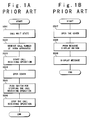
- Figs. 1A and 1B are a flow chart of stopping of a call receiving operation and a flow chart of confirmation of a reception message in an example of a conventional wireless selective call receiver, respectively.
- the conventional wireless selective call receiver has a cover for body protection.
- the reception wait state step S501 in which the cover is closed, when its call number is received (step S502), the call receiving operation such as speaker ringing and so on is performed (step S503).
- a user opens the cover (step S504) and then pushes a call receiving operation stop switch (step S505). As a result, the call receiving operation is stopped (step S506).
- step S507 the user opens the cover of the wireless selective call receiver (step S507) and then pushes a message display switch (step S508) such that message display is performed (step S509).
- the contents which are displayed on the display section during a reception wait state are only situation of electric field strength in communication with a wireless communication base. Because the microphone flip section must be opened to reply to a call, only the effect of protection of the liquid crystal surface can be expected in the reception wait state.
- the wireless selective call receiver has the peculiar functions of the stop operation of a call receiving operation and the confirmation operation of a reception message. Therefore, the conventional wireless selective call receiver can not achieve these functions in the state in which the cover is closed.
- An object of the present invention is to provide a method of receiving a call with a message data in which the stop operation of a call receiving operation and the confirmation operation of a reception message can be performed in the state in which a cover is closed, and a wireless selective call receiver for the method.
- a wireless selective call receiver includes a body section composed of an display panel, a control section having a memory and built in the body section, and an operation unit, and a cover section connected to the body section and composed of a cover for protecting the display panel and a transparent window provided in correspondence with the display panel such that a display on the display panel can be seen through the transparent window in a cover closing state that the cover section is closed.
- the control section controls the display panel in response to an operation of the operation unit such that a message data is displayed on the display panel.
- the operation unit is operable in the cover closing state.
- the operation unit includes a control switch for instructing stop of a call receiving operation to the control section, and for instructing display of a message to the control section.
- the control switch may further instructs power off to the control section.
- the operation unit may include a first control switch for instructing stop of a call receiving operation to the control section, and a second control switch for instructing display of a message to the control section.
- the operation unit may include a third control switch further instructs power off to the control section.
- a first determining section determines whether a call is received in a call wait state, and an informing section of the control section informs to a user that the call is received when the call is received in the call receiving state.
- the control section includes section for control the display panel to display a latest message data when the operation unit is operated in the call wait state.
- a second determining section determines whether the operation unit is operated during the informing operation, and the control section includes a section for stopping the informing operation, for storing in the memory a message data received subsequently to the call, and for control the display panel to display the message data received subsequently to the call as a current message data, when the operation unit is operated during the informing operation.
- the control section includes section for storing the message data received subsequently to the call in the memory. After the storing of the message data, the control section is set to the call wait state when the operation unit is not operated during the informing operation.
- a third determining section determines whether the operation unit is operated while the current message data is displayed, and the control section includes a section for controlling the display panel to sequentially display as current message data message data which have been already received and stored in the memory, each time the operation unit is operated while the current message data is displayed.
- the control section is set to the call wait state.
- a fourth determining section determines whether the operation unit continues to be operated during a first predetermined time period, and the control section includes a section for controlling the display panel to display a power-off message data when the operation unit continues to be operated during the first predetermined time period.
- a fifth determining section determines whether the operation unit is operated while the power-off message data is displayed, and the control section includes a section for turning off a power supply when the operation unit is not operated while the power-off message data is displayed, for controlling the display panel to perform a clock display when the operation unit is operated while the power-off message data is displayed, and for turning off the power supply when the operation unit is operated while the clock display is performed or after the clock display is performed during a second predetermined time period.
- a method of receiving a call with a message data in a wireless selective call receiver includes the steps of:
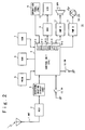
- Fig. 2 is a block diagram of the wireless selective call receiver according to the first embodiment of the present invention.
- Fig. 3 is a perspective view which shows the outside appearance of the wireless selective call receiver shown in Fig. 2.
- the wireless selective call receiver of the first embodiment of the present invention is composed of an antenna (ANT) 1, a receiving section (REC) 2, a waveform shaping circuit (CNV) 3, a control unit (CTL) 4, a programmable read only memory (PROM) 5, a random access memory (RAM) 6, a read only memory (ROM) 7, an operation panel (PNL) 8, a liquid crystal device (LCD) 10, an LCD driver (DRV) 9, a speaker 12, amplifiers (AMPA) 11 and (AMPB) 13, a light emitting diode (LED) 14, a control switch (SW) 15, and a power supply switch (PW) 16 for an electronic pocket diary function.
- the control unit (CTL) 4 includes timers 4-1 and 4-2 for counting time periods t1 and t2, respectivley.
- the PROM 5 stores a selective call number of the wireless selective call receiver in advance
- the RAM 6 stores a telephone book data, a scheduler data, a message data which is analyzed by the control unit (CTL) 4 and so on
- the ROM 7 stores a dictionary function data and so on in advance.
- the receiving section (REC) 2 receives a radio signal from a wireless communication base (not illustrated) through the antenna (ANT) 1 to amplify and demodulate the received signal.
- the waveform shaping circuit (CNV) 3 converts the demodulated signal into a digital signal.
- the operation panel (PNL) 8 is used for a user to input a required data or instruction.
- the LCD driver (DRV) 9 outputs a display signal to the LCD 10 such that a reception message, a menu and so on are displayed.
- the amplifier (AMPA) 11 amplifies a speaker alert signal outputted from the control unit (CTL) 4 and the speaker (SPK) 12 outputs the speaker alert signal from the amplifier (AMPA) 11 with a loud sound.
- the amplifier (AMPB) 13 amplifies an LED alert signal outputted from the control unit (CTL) 4 and the LED 14 is lighted by the LED alert signal from the amplifier (AMPB) 13.
- the control unit (CTL) 4 performs the control of various sections of the wireless selective call receiver.
- the control switch (SW) 15 is used to instruct the control unit (CTL) 4 to control a stop operation of a call receiving operation and a confirmation operation of a reception message.
- the wireless selective call receiver 20 is composed of a body section 21 and a cover section 22.
- the body section 21 is composed of the LCD 10 and the operation panel 8 which is provided on the LCD 10.
- the body section 21 is further composed of the control switch (SW) 15 and a hole which are provided on the side wall.
- a pen 17 is accommodated in the hole. By touching the operation panel (PNL) 8 by the pen 17, a data and an instruction can be inputted to the control unit (CTL) 4.
- CTL control unit
- the cover section 22 is connected to the body section by a hinge and is composed of a cover 18 and a transparent window 19 which is provided in the center portion of the cover 18 in correspondence to the LCD 10 and the operation panel (PNL) 8.
- the cover 18 protects the operation panel (PNL) 8 from impact and flaw.
- the cover is formed to have the structure such that the cover can be opened or closed from or to the body section by the hinge.
- the wireless selective call receiver has a management function of the data which contains a telephone book data and a scheduler data. Also, the wireless selective call receiver has the structure by which the contents which are displayed on the LCD 10 can be recognized through a transparent window 19 in the state in which a cover 18 is closed, as shown in Fig. 2. Further, the wireless selective call receiver has the structure by which a menu displayed on the LCD 10 can be performed by, for example, touching the operation panel (PNL) 8 by the pen 17 in the state in which the cover 18 is closed.
- PNL operation panel
- the radio signal is received by the antenna (ANT) 1 and is amplified and demodulated by the receiving section (REC) 2.
- the demodulated radio signal is converted into the digital signal which can read by the control unit (CTL) 4, by the waveform shaping circuit (CNV) 3.
- CTL control unit
- the data signal outputted from the waveform shaping circuit (CNV) 3 and the selective call number of the call receiver read out from the PROM 5 are compared.
- the alert signal is outputted to the amplifier (AMPA) 11 and the amplifier (AMPB) 12 to inform the user that a call is received.
- control unit (CTL) 4 analyzes a message signal which follows the selective call number and outputs a reception message data as the analysis result to LCD driver (DRV) 9.
- the LCD driver (DRV) 9 drives the LCD 10 such that the LCD 10 displays a reception message data on the display screen. Also, the control unit (CTL) 4 stores the reception message data in the RAM 6.
- the amplifier (AMPA) 11 amplifies the speaker alert signal from the control unit (CTL) 4 to generate a speaker drive signal for driving the speaker (SPK) 12.
- the speaker (SPK) 12 converts the speaker drive signal into a sound signal to output an alert sound for informing the user of receiving a call.
- the amplifier (AMPB) 13 amplifies the LED alert signal from the control unit (CTL) 4 to send out to the LED 14. The LED 14 is lighted in response to this LED alert signal to inform the user of the receiving the call.
- switch (SW) 15 is used in common to the stop operation of a call receiving operation and the confirmation operation a reception message data, two independent switches may be provided in place of the single switch 15.
- An operation procedure data as menus are displayed on the LCD 10 by the control unit (CTL) 4.
- the user indirectly touches the operation panel (PNL) 8 through the transparent window 19 using the pen 17 to select one of the operation procedure data.
- the control unit (CTL) 4 recognizes the position of the operation panel (PNL) 8 touched by the user with the pen to execute the specified function operation.
- the control unit (CTL) 4 stores these data in the RAM 6.
- the control unit (CTL) 4 can read out these data in accordance with the touching operation to the operation panel (PNL) 8 to display on the LCD 10 again.
- the control unit (CTL) 4 refers to a dictionary function data previously stored in the ROM 7 to convert the Kana letters into a list of Kanji letters and to display the list of Kanji letters on the LCD 10.
- a desired Kanji letter is selected from among these Kanji letters by the user. This selection allows a Kanji data input.
- Fig. 4 is a flow chart to explain the operation from the call receiving operation stop operation to the message confirmation operation after the message reception in the wireless selective call receiver according to the first embodiment of the present invention.
- the wireless selective call receiver When the user turns on the switch (PW) 16, the wireless selective call receiver is set to a reception wait state (step S301). If a message with a call number of the wireless selective call receiver is received by the antenna (ANT) 1 in this state (Y in step S302), the above-mentioned call receiving operation is performed to output the speaker alert sound from the control unit (CTL) 4 to the speaker (SPK) 12 and at the same time to display the reception message data on the LCD 10 (step S303).
- CTL control unit
- SPK speaker
- step S306 If the user pushes the switch (SW) 15 during message display (Y in S306) and there is a message data which has been received previous to the reception message data currently displayed in the RAM 6 (Y in step S307), this previous reception message data is displayed as a new message data after the message currently displayed (step S308). Then, every time the user pushes the control switch (SW) 15, a new message data is displayed in the received order. A procedure from step S306 to step S308 is repeated until the earliest received message data which is stored in the RAM 6 is displayed.
- step S307 if being N in step S307, that is, if there is no message data which has been received previously to the message currently displayed, the control returns to the reception wait state of step S301 after the display of the LCD 10 is turned off (step S310).
- step S306 that is, if the user does not push the control switch (SW) 15 during the message display, the display of the message data is continued until the preset time period t1 elapses and after this time period t1 elapses (Y in step S309), the message data display is turned off (step S310) and then the control returns to step S301.
- step S304 that is, if the user does not push the control switch (SW) 15 during the call receiving operation, the call receiving operation is continued until a preset time period t2 elapses (N in step S311). After this time period t2 elapsed (Y in step S311), the call receiving operation is stopped, i.e., automatically reset (step S312). Then, the control returns to step S301.
- step S302 that is, if the user pushes the control switch (SW) 15 in the normal reception wait state in which the call receiving operation is not performed (Y in step S313), the latest reception message is displayed on the LCD 10 (step S314). Then, the control goes to step S306. On the other hand, if being N in step S313, that is, if the user does not push the control switch (SW) 15, the control returns to step S301 to maintain the reception wait state.
- the control unit (CTL) further includes timers 4-3 to 4-5 for counting time periods t3, t4 and t5, respectivley.
- the control switch (SW) 15 in the first embodiment shown in Fig. 2 is also used as the power supply switch of the wireless selective call receiver, in place of the switch (PW) 16.
- the control switch (SW) 15 is continuously pushed during a preset time period t3, the power supply of the wireless selective call receiver can be turned on or off.
- the control unit (CTL) 4 displays a power-off informing data indicating that the power supply is turned off, during a preset time period t4. After the power- off informing data disappears after the preset time period t4 elapsed, the power supply of the wireless selective call receiver function is turned off. On the other hand, if the user pushes the control switch (SW) 15 while the power-off informing data is displayed, the switching operation to the power-off state is canceled.
- the user since it is possible for the user to recognize the display on the LCD 10 in the state in which the cover 18 is closed, when the user pushes the control switch (SW) 15 during the display of the power-off informing data to cancel the switching operation to the power- off state, the user can recognize a current time without doing any troublesome operation by performing a clock display during a predetermined time period t5.
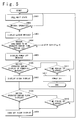
- Fig. 5 is a flow chart to explain an on or off operation of the power supply of the wireless selective call receiver according to the second embodiment of the present invention.
- the power supply of the wireless selective call receiver is turned on such that the wireless selective call receiver is set to the reception wait state (step S401).
- the control switch (SW) 15 Y in S402
- the latest one of the reception message data which has been stored in the RAM 6 is displayed on the LCD 10 (step S403).
- step S404 If the user stops the pushing of the control switch (SW) 15 (N in step S404) before the preset time period t3 elapses, the control goes to step S314 shown in Fig. 4 to execute the confirmation operation of the reception message data. However, if the control switch SW 15 continues to be pushed until the preset time period t3 elapses (Y in step S404), the display of power-off informing data of the wireless selective call receiver is performed on the LCD 10 (step S405).
- step S406 If the user does not push the control switch (SW) 15 during the display of the power-off informing data (N in step S406), the display is turned off (Y in step S411) after the display is performed during the preset time period t4. Then, the power supply of the wireless selective call receiver is also turned off (step S412). The control ends in this manner.
- step S406 that is, if the user pushes the control switch (SW) 15 during the display of the power-off informing data, the power supply off operation is canceled. A clock display at this point is performed on the LCD 10 (step S407).
- step S408 If the user does not push the control switch (SW) 15 during this clock display (N in step S408), the clock display is turned off (step S409) after the display is performed during a preset time period t5 (Y in step S410). Then, the control returns to step S401 to set the reception wait state again. Also, even if the user pushes the control switch (SW) 15 during the clock display (Y in step S408), the control goes to step S409 and thereafter it returns to step S401.
- the wireless selective call receiver has the management function of the data which contains a telephone book data and a scheduler data.
- the above-mentioned cover has a transparent window in the position which corresponds to the display section in the state in which the cover is closed.
- the pen is provided which is used to touch the operation panel and which is accommodated in a position detachable in the state in which the cover is closed. Therefore, in the wireless selective call receiver, the content displayed on the display section can be recognized in the state in which the cover is closed without opening the cover of the wireless selective call receiver.
- the wireless selective call receiver can execute the menu displayed on the display section in the state in which the cover is closed. In this manner, the operation of the wireless selective call receiver can be remarkably simplified and the operability can be improved.
- the above-mentioned operations are executed by the operation of a switch for the call receiving operation stop operation and a switch for the reception message confirmation operation which are provided in the positions where it is possible to push them in the state which the cover is closed.
- the wireless selective call receiver is further composed of a switch for the power one or off of the wireless selective call receiver.
- a single switch may be used for the call receiving operation stop operation, the reception message confirmation operation and the power supply on or off operation of the wireless selective call receiver.
Landscapes
- Physics & Mathematics (AREA)
- Engineering & Computer Science (AREA)
- Computer Networks & Wireless Communication (AREA)
- Electromagnetism (AREA)
- General Physics & Mathematics (AREA)
- Mobile Radio Communication Systems (AREA)
Applications Claiming Priority (3)
| Application Number | Priority Date | Filing Date | Title |
|---|---|---|---|
| JP100025/96 | 1996-04-22 | ||
| JP10002596 | 1996-04-22 | ||
| JP08100025A JP3088282B2 (ja) | 1996-04-22 | 1996-04-22 | 無線選択呼出受信機 |
Publications (2)
| Publication Number | Publication Date |
|---|---|
| EP0803849A1 true EP0803849A1 (fr) | 1997-10-29 |
| EP0803849B1 EP0803849B1 (fr) | 2001-06-27 |
Family
ID=14263006
Family Applications (1)
| Application Number | Title | Priority Date | Filing Date |
|---|---|---|---|
| EP97105222A Expired - Lifetime EP0803849B1 (fr) | 1996-04-22 | 1997-03-27 | Récepteur d'appels sélectifs sans fil fonctionnant avec couvercle fermé |
Country Status (4)
| Country | Link |
|---|---|
| US (1) | US5956656A (fr) |
| EP (1) | EP0803849B1 (fr) |
| JP (1) | JP3088282B2 (fr) |
| DE (1) | DE69705351T2 (fr) |
Cited By (2)
| Publication number | Priority date | Publication date | Assignee | Title |
|---|---|---|---|---|
| GB2355149A (en) * | 1999-10-08 | 2001-04-11 | Nokia Mobile Phones Ltd | Portable device with access to display functions when cover is closed |
| US7313389B1 (en) | 1999-10-08 | 2007-12-25 | Nokia Corporation | Portable telecommunication device |
Families Citing this family (25)
| Publication number | Priority date | Publication date | Assignee | Title |
|---|---|---|---|---|
| JP3606498B2 (ja) * | 1996-04-26 | 2005-01-05 | 三菱電機株式会社 | 携帯情報端末装置 |
| JPH1118157A (ja) * | 1997-06-26 | 1999-01-22 | Saitama Nippon Denki Kk | 折畳み式携帯電話機 |
| US6560461B1 (en) | 1997-08-04 | 2003-05-06 | Mundi Fomukong | Authorized location reporting paging system |
| US6377966B1 (en) * | 1997-10-22 | 2002-04-23 | Flashpoint Technology, Inc. | Graphical interface to select characters representing phonetic articulation and no articulation groups |
| DE69829232T2 (de) * | 1997-12-29 | 2005-07-21 | Samsung Electronics Co., Ltd., Suwon | Mobilkommunikationsendgerät mit der Anzeige überlagertem flächigem Berührungssensor |
| JP2972702B2 (ja) * | 1998-03-17 | 1999-11-08 | 静岡日本電気株式会社 | ペン入力型携帯情報端末機 |
| FI109731B (fi) * | 1998-06-02 | 2002-09-30 | Nokia Corp | Elektroniikkalaite ja ohjauselin |
| US6434403B1 (en) * | 1999-02-19 | 2002-08-13 | Bodycom, Inc. | Personal digital assistant with wireless telephone |
| JP2000253113A (ja) * | 1999-02-26 | 2000-09-14 | Hitachi Ltd | 情報通信端末装置 |
| KR100381139B1 (ko) * | 2001-01-17 | 2003-04-18 | 삼성전자주식회사 | 폴더타입 휴대용 무선 단말기에서의 메시지 디스플레이 방법 |
| US7003333B2 (en) * | 2002-09-17 | 2006-02-21 | Motorola, Inc. | Latch mechanism and electronic device employing a latch mechanism |
| JP3778181B2 (ja) * | 2003-06-13 | 2006-05-24 | セイコーエプソン株式会社 | ディスプレイ制御装置 |
| CN1627851A (zh) * | 2003-12-09 | 2005-06-15 | 三星电子株式会社 | 在无线电话中利用动漫形象来告警日程的方法 |
| GB0411314D0 (en) * | 2004-05-21 | 2004-06-23 | Koninkl Philips Electronics Nv | Electronic device with multiple array devices |
| US7507588B2 (en) * | 2005-04-20 | 2009-03-24 | Becton, Dickinson And Company | Multiplex microparticle system |
| US9883019B2 (en) * | 2005-04-28 | 2018-01-30 | Kyocera Corporation | Mobile communication terminal and software update method |
| US7817745B2 (en) * | 2005-06-02 | 2010-10-19 | Adaptive Spectrum And Signal Alignment, Inc. | Tonal precoding |
| US8462746B2 (en) * | 2006-12-27 | 2013-06-11 | Altair Semiconductor Ltd. | Wireless receiver with intermittent shut-off of RF circuits |
| US7881252B2 (en) | 2006-12-27 | 2011-02-01 | Altair Semiconductor Ltd. | Wireless receiver with intermittent shut-off of RF circuits |
| US20090054112A1 (en) * | 2007-08-24 | 2009-02-26 | Motorola, Inc. | Display for portable electronic device |
| JP2011523512A (ja) * | 2007-12-24 | 2011-08-11 | アルタイル セミコンダクター リミテッド | Rf回路の中間遮断機能を有する無線受信器 |
| WO2012104749A1 (fr) | 2011-02-02 | 2012-08-09 | Altair Semiconductor Ltd. | Coupure intermittente de la circuiterie rf dans des terminaux de communication sans fil |
| US8955678B2 (en) | 2013-03-14 | 2015-02-17 | Pelican Products, Inc. | Protective cases for mobile electronic communication devices |
| CN105912899A (zh) * | 2016-03-31 | 2016-08-31 | 联想(北京)有限公司 | 一种控制电子设备的方法以及电子设备 |
| US9831905B1 (en) | 2016-10-12 | 2017-11-28 | Pelican Products, Inc. | Control feature of a protective case for engaging a switch of an electronic device |
Citations (5)
| Publication number | Priority date | Publication date | Assignee | Title |
|---|---|---|---|---|
| JPH0530166A (ja) * | 1991-07-23 | 1993-02-05 | Matsushita Electric Ind Co Ltd | 携帯無線電話装置 |
| JPH0629906A (ja) * | 1992-03-24 | 1994-02-04 | Nec Corp | 無線選択呼出受信機 |
| EP0594459A1 (fr) * | 1992-10-23 | 1994-04-27 | Nec Corporation | Récepteur d'appel de personnes par radio |
| EP0594430A1 (fr) * | 1992-10-21 | 1994-04-27 | Nec Corporation | Dispositif d'appel de personnes par radio |
| US5452829A (en) * | 1993-11-18 | 1995-09-26 | Motorola, Inc. | Integrated lens and holster assembly |
Family Cites Families (13)
| Publication number | Priority date | Publication date | Assignee | Title |
|---|---|---|---|---|
| US5023905A (en) * | 1988-07-25 | 1991-06-11 | Reflection Technology, Inc. | Pocket data receiver with full page visual display |
| KR930002751B1 (ko) * | 1988-09-29 | 1993-04-09 | 삼성전자주식회사 | 페이저수신기에서 자기 어드레스데이타 표시장치 |
| JP2626118B2 (ja) * | 1990-01-16 | 1997-07-02 | 日本電気株式会社 | 無線選択呼出受信機およびその収容ケース |
| JPH04123426A (ja) * | 1990-09-14 | 1992-04-23 | Hitachi Ltd | 半導体熱処理装置 |
| US5335246A (en) * | 1992-08-20 | 1994-08-02 | Nexus Telecommunication Systems, Ltd. | Pager with reverse paging facility |
| JPH0742251A (ja) * | 1993-08-03 | 1995-02-10 | Noriaki Tokunaga | 建物における壁面パネル相互の縦目地構造 |
| US5414444A (en) * | 1994-03-30 | 1995-05-09 | At&T Corp. | Personal communicator having orientable video imaging element |
| JP2690685B2 (ja) * | 1994-04-18 | 1997-12-10 | 静岡日本電気株式会社 | 表示機能付携帯無線機 |
| JPH0856375A (ja) * | 1994-06-07 | 1996-02-27 | Sony Corp | 無線呼出し機能付端末 |
| US5584054A (en) * | 1994-07-18 | 1996-12-10 | Motorola, Inc. | Communication device having a movable front cover for exposing a touch sensitive display |
| US5588041A (en) * | 1995-01-05 | 1996-12-24 | Motorola, Inc. | Cellular speakerphone and method of operation thereof |
| JP2693936B2 (ja) * | 1995-11-13 | 1997-12-24 | 静岡日本電気株式会社 | 保護蓋付き無線選択呼出受信機 |
| JP2986393B2 (ja) * | 1995-12-26 | 1999-12-06 | 山形カシオ株式会社 | 携帯端末自動呼び出し装置 |
-
1996
- 1996-04-22 JP JP08100025A patent/JP3088282B2/ja not_active Expired - Fee Related
-
1997
- 1997-03-25 US US08/829,815 patent/US5956656A/en not_active Expired - Fee Related
- 1997-03-27 EP EP97105222A patent/EP0803849B1/fr not_active Expired - Lifetime
- 1997-03-27 DE DE69705351T patent/DE69705351T2/de not_active Expired - Fee Related
Patent Citations (5)
| Publication number | Priority date | Publication date | Assignee | Title |
|---|---|---|---|---|
| JPH0530166A (ja) * | 1991-07-23 | 1993-02-05 | Matsushita Electric Ind Co Ltd | 携帯無線電話装置 |
| JPH0629906A (ja) * | 1992-03-24 | 1994-02-04 | Nec Corp | 無線選択呼出受信機 |
| EP0594430A1 (fr) * | 1992-10-21 | 1994-04-27 | Nec Corporation | Dispositif d'appel de personnes par radio |
| EP0594459A1 (fr) * | 1992-10-23 | 1994-04-27 | Nec Corporation | Récepteur d'appel de personnes par radio |
| US5452829A (en) * | 1993-11-18 | 1995-09-26 | Motorola, Inc. | Integrated lens and holster assembly |
Non-Patent Citations (2)
| Title |
|---|
| PATENT ABSTRACTS OF JAPAN vol. 017, no. 317 (E - 1382) 16 June 1993 (1993-06-16) * |
| PATENT ABSTRACTS OF JAPAN vol. 018, no. 240 (E - 1545) 9 May 1994 (1994-05-09) * |
Cited By (3)
| Publication number | Priority date | Publication date | Assignee | Title |
|---|---|---|---|---|
| GB2355149A (en) * | 1999-10-08 | 2001-04-11 | Nokia Mobile Phones Ltd | Portable device with access to display functions when cover is closed |
| GB2355149B (en) * | 1999-10-08 | 2003-12-17 | Nokia Mobile Phones Ltd | A portable device |
| US7313389B1 (en) | 1999-10-08 | 2007-12-25 | Nokia Corporation | Portable telecommunication device |
Also Published As
| Publication number | Publication date |
|---|---|
| JP3088282B2 (ja) | 2000-09-18 |
| JPH09289662A (ja) | 1997-11-04 |
| US5956656A (en) | 1999-09-21 |
| EP0803849B1 (fr) | 2001-06-27 |
| DE69705351D1 (de) | 2001-08-02 |
| DE69705351T2 (de) | 2002-05-02 |
Similar Documents
| Publication | Publication Date | Title |
|---|---|---|
| US5956656A (en) | Wireless selective call receiver operable in cover closing state | |
| US6907276B2 (en) | Mobile communication terminal with external display unit | |
| US6959208B2 (en) | Portable terminal | |
| US5933783A (en) | Portable terminal | |
| US20020168947A1 (en) | Integral navigation keys for a mobile handset | |
| JP4147016B2 (ja) | 携帯端末 | |
| EP1156640A2 (fr) | Unité de communication portable et pliable | |
| KR20010034141A (ko) | 무선 통신 장치에 있어서 키의 의도하지 않은 활성화를방지하기 위한 장치 및 방법 | |
| EP1458171B1 (fr) | Terminal mobile intégré et méthode de contrôle d'un afficheur extérieur | |
| AU3507701A (en) | Portable telephone | |
| KR100334214B1 (ko) | 무선선택호출수신기 | |
| US6037878A (en) | Paging apparatus and paging method by password | |
| JP4124244B2 (ja) | 携帯電話 | |
| KR100630099B1 (ko) | 휴대폰에서 스케쥴 표시 방법 | |
| JP4123268B2 (ja) | 携帯電話 | |
| JP3915827B2 (ja) | 携帯電話 | |
| JP4124271B2 (ja) | 携帯電話 | |
| JP2001345927A (ja) | 移動体通信端末 | |
| KR20000002386U (ko) | 특정 메시지의 수신을 알리는 발광소자를 구비한 개인용 무선호출기 | |
| JPH06197067A (ja) | 受信装置 | |
| JPH11146044A (ja) | 電話機 | |
| JP2003204391A (ja) | 照明機能付携帯機器 | |
| HK1015502B (en) | Radio paging receiver |
Legal Events
| Date | Code | Title | Description |
|---|---|---|---|
| PUAI | Public reference made under article 153(3) epc to a published international application that has entered the european phase |
Free format text: ORIGINAL CODE: 0009012 |
|
| AK | Designated contracting states |
Kind code of ref document: A1 Designated state(s): DE FR GB |
|
| 17P | Request for examination filed |
Effective date: 19980202 |
|
| 17Q | First examination report despatched |
Effective date: 20000331 |
|
| GRAG | Despatch of communication of intention to grant |
Free format text: ORIGINAL CODE: EPIDOS AGRA |
|
| GRAG | Despatch of communication of intention to grant |
Free format text: ORIGINAL CODE: EPIDOS AGRA |
|
| GRAH | Despatch of communication of intention to grant a patent |
Free format text: ORIGINAL CODE: EPIDOS IGRA |
|
| GRAH | Despatch of communication of intention to grant a patent |
Free format text: ORIGINAL CODE: EPIDOS IGRA |
|
| GRAA | (expected) grant |
Free format text: ORIGINAL CODE: 0009210 |
|
| AK | Designated contracting states |
Kind code of ref document: B1 Designated state(s): DE FR GB |
|
| REF | Corresponds to: |
Ref document number: 69705351 Country of ref document: DE Date of ref document: 20010802 |
|
| ET | Fr: translation filed | ||
| REG | Reference to a national code |
Ref country code: GB Ref legal event code: IF02 |
|
| PLBE | No opposition filed within time limit |
Free format text: ORIGINAL CODE: 0009261 |
|
| STAA | Information on the status of an ep patent application or granted ep patent |
Free format text: STATUS: NO OPPOSITION FILED WITHIN TIME LIMIT |
|
| 26N | No opposition filed | ||
| PGFP | Annual fee paid to national office [announced via postgrant information from national office to epo] |
Ref country code: GB Payment date: 20070321 Year of fee payment: 11 |
|
| PGFP | Annual fee paid to national office [announced via postgrant information from national office to epo] |
Ref country code: DE Payment date: 20070322 Year of fee payment: 11 |
|
| PGFP | Annual fee paid to national office [announced via postgrant information from national office to epo] |
Ref country code: FR Payment date: 20070308 Year of fee payment: 11 |
|
| GBPC | Gb: european patent ceased through non-payment of renewal fee |
Effective date: 20080327 |
|
| REG | Reference to a national code |
Ref country code: FR Ref legal event code: ST Effective date: 20081125 |
|
| PG25 | Lapsed in a contracting state [announced via postgrant information from national office to epo] |
Ref country code: DE Free format text: LAPSE BECAUSE OF NON-PAYMENT OF DUE FEES Effective date: 20081001 |
|
| PG25 | Lapsed in a contracting state [announced via postgrant information from national office to epo] |
Ref country code: FR Free format text: LAPSE BECAUSE OF NON-PAYMENT OF DUE FEES Effective date: 20080331 |
|
| PG25 | Lapsed in a contracting state [announced via postgrant information from national office to epo] |
Ref country code: GB Free format text: LAPSE BECAUSE OF NON-PAYMENT OF DUE FEES Effective date: 20080327 |