EP0804267B1 - Systeme a deflecteurs a events - Google Patents
Systeme a deflecteurs a events Download PDFInfo
- Publication number
- EP0804267B1 EP0804267B1 EP96905152A EP96905152A EP0804267B1 EP 0804267 B1 EP0804267 B1 EP 0804267B1 EP 96905152 A EP96905152 A EP 96905152A EP 96905152 A EP96905152 A EP 96905152A EP 0804267 B1 EP0804267 B1 EP 0804267B1
- Authority
- EP
- European Patent Office
- Prior art keywords
- panel member
- tank
- peripheral
- baffle
- wall
- Prior art date
- Legal status (The legal status is an assumption and is not a legal conclusion. Google has not performed a legal analysis and makes no representation as to the accuracy of the status listed.)
- Expired - Lifetime
Links
- 230000002093 peripheral effect Effects 0.000 claims abstract description 52
- 238000013022 venting Methods 0.000 claims abstract description 15
- 239000007788 liquid Substances 0.000 claims description 9
- 238000004891 communication Methods 0.000 claims description 6
- 239000012530 fluid Substances 0.000 claims description 6
- 239000007787 solid Substances 0.000 claims description 4
- 239000011152 fibreglass Substances 0.000 claims description 3
- 239000002131 composite material Substances 0.000 claims description 2
- 239000007789 gas Substances 0.000 abstract description 10
- 230000000153 supplemental effect Effects 0.000 description 3
- 230000006378 damage Effects 0.000 description 2
- 238000009434 installation Methods 0.000 description 2
- 241000446313 Lamella Species 0.000 description 1
- 208000027418 Wounds and injury Diseases 0.000 description 1
- 238000001311 chemical methods and process Methods 0.000 description 1
- 238000010276 construction Methods 0.000 description 1
- 230000005484 gravity Effects 0.000 description 1
- 208000014674 injury Diseases 0.000 description 1
- 238000004519 manufacturing process Methods 0.000 description 1
- 239000000463 material Substances 0.000 description 1
- 238000000034 method Methods 0.000 description 1
- 229920001084 poly(chloroprene) Polymers 0.000 description 1
- 230000009467 reduction Effects 0.000 description 1
- 239000010802 sludge Substances 0.000 description 1
- 239000003351 stiffener Substances 0.000 description 1
- 239000002699 waste material Substances 0.000 description 1
- 239000002351 wastewater Substances 0.000 description 1
Images


Classifications
-
- B—PERFORMING OPERATIONS; TRANSPORTING
- B01—PHYSICAL OR CHEMICAL PROCESSES OR APPARATUS IN GENERAL
- B01D—SEPARATION
- B01D21/00—Separation of suspended solid particles from liquids by sedimentation
- B01D21/24—Feed or discharge mechanisms for settling tanks
- B01D21/2494—Feed or discharge mechanisms for settling tanks provided with means for the removal of gas, e.g. noxious gas, air
-
- B—PERFORMING OPERATIONS; TRANSPORTING
- B01—PHYSICAL OR CHEMICAL PROCESSES OR APPARATUS IN GENERAL
- B01D—SEPARATION
- B01D21/00—Separation of suspended solid particles from liquids by sedimentation
- B01D21/0003—Making of sedimentation devices, structural details thereof, e.g. prefabricated parts
-
- B—PERFORMING OPERATIONS; TRANSPORTING
- B01—PHYSICAL OR CHEMICAL PROCESSES OR APPARATUS IN GENERAL
- B01D—SEPARATION
- B01D21/00—Separation of suspended solid particles from liquids by sedimentation
- B01D21/0039—Settling tanks provided with contact surfaces, e.g. baffles, particles
-
- B—PERFORMING OPERATIONS; TRANSPORTING
- B01—PHYSICAL OR CHEMICAL PROCESSES OR APPARATUS IN GENERAL
- B01D—SEPARATION
- B01D21/00—Separation of suspended solid particles from liquids by sedimentation
- B01D21/0039—Settling tanks provided with contact surfaces, e.g. baffles, particles
- B01D21/0042—Baffles or guide plates
Definitions
- This invention relates generally to a system comprising a plurality of baffles arranged in a clarifier tank for gravitationally separating solids suspended in a liquid contained in the tank, the system comprises a plurality of interengaged individual vented baffles secured to the clarifier tank peripheral wall
- the present invention relates generally to system comprising baffles arranged in a clarifier tank for gravitationally separating solids suspended in a liquid contained in the tank.
- baffle devices are also known in the art as a lamella gravity separator or settler.
- the clarifiers with which the inventive baffle device is used typically consist of a circular or rectangularlyconfigured tank in which a centrally mounted, radially-extended arm is slowly moved or rotated about the tank at or proximate the surface of the carrier liquid.
- U.S.-A-5,252,205 to Schaller is referred to.
- the present invention provides a vented baffle that is mounted in cantilevered fashion along a peripheral wall of the clarifier intermediate the tank bottom and the surface of the carrier liquid contained in the tank.
- the vented baffle system includes a plurality of such baffles which are constructed as modular units and form a continuous, single-surface sheet that slopes downwardly from the peripheral tank wall toward the center of the tank and terminates at a free edge suspended in spaced relation above the tank bottom. More specifically, each panel member which is downwardly sloping from the peripheral tank wall toward the interior of the tank and the tank bottom, is provided with a lower side and an upper side. The panel member extends downwardly from an upper edge secured to the peripheral tank wall to a lower edge disposed in spaced relation to the tank bottom.
- the panel member has a first lateral side and a second lateral side with the panel member defining a space formed between the junction of the lower side of the panel member and the peripheral tank wall. Due to the inclined configuration of these baffles, air may be trapped during the filling of the tank in a space formed between the junction of the lower side of the panel member and the peripheral tank wall. As well other gases which may form naturally as a part of the chemical processes which take place within the clarifier may be trapped in this space. Accordingly, the forces imposed by these gases on the baffle require that the baffle be constructed and mounted in such a manner that will withstand these forces. As well, the build up of pressure from these gases can be extreme with damage and/or personal injury resulting unless some form of venting is provided.
- a common form of venting relies on one or more holes drilled in the baffle panel member to continually vent the gas to the surface and alleviate the build up of pressure. Small holes (1 inch diameter or less) however rapidly become clogged with sludge and become ineffective. Larger holes allow the continual upflow of waste solids and can create a negative impact on the performance of the baffle.
- an object of the present invention to provide a system of plural integrated vented baffles arranged in a tank, the baffles being curved to match the peripheral contour of a circular or arcuate tank or, alternatively, linear to match the peripheral walls of a non-circular tank, and which interlock to form a rigid "shelf” or baffle system inclined inward and downward around the entire periphery of the tank.
- Another object of the invention is to provide a relief conduit passage in fluid communication with the space formed between the junction of the lower side of the panel member and the peripheral tank wall preventing the pressure in the space and which is integrally molded into the mounting flange.
- a system formed of a plurality of individual baffles arranged in a clarifier tank includes a plurality of interengaged individual baffles with each baffle having a unitarily integrated design incorporating a panel member, an end-depending mounting bracket, a mounting flange and a relief conduit.
- the panel member slopes downwardly from the peripheral tank wall toward the tank bottom and defines a first lateral side end and a second lateral side end.
- the end bracket is integrally arranged at the first side end for securing the panel member to the radially inwardly facing peripheral wall of the clarifier tank.
- each baffle is configured for preferably interlocked securement to the first side end of a next adjacently-located one of the plural baffles.
- inventive vented baffle system which is mounted in cantilevered fashion along the peripheral wall of the clarifier intermediate the bottom of the tank and the surface of the contained liquid in the tank, forms a continuous single-surface sheet or "shelf" that slopes downwardly from the peripheral tank wall toward the center of the tank and terminates at a free edge suspended in spaced relation above the tank bottom.
- the panel member is further provided with a supplemental mounting flange along the top or upper edge of the member.
- the supplemental mounting flange may be unitarily formed along the upper edge of the panel member to thereby provide additional support and securement of the panel member to the peripheral wall of the clarifier tank.
- the panel member may also or alternatively be provided with a unitary-integral rigidizing flange depending from and extending along the lower edge of the panel member for providing additional structural strength thereto, particularly along the rigidizing flange, which serves as a stiffening member for the lower, only indirectly supported portion of the panel member.
- the rigidizing flange also contributes to deflection of density currents and redirection of liquid flow back into the central volume of the tank.
- a relief conduit is provided near the top of each baffle panel.
- venting conduits or passages are provided which are unitarily integrated in the mounting flange. In this way, the venting conduits or passages provide continuous venting of the pressure in the space formed between the junction of the lower side of the panel member and the peripheral tank wall thereby alleviating the build up of pressure. If mounting flanges are not utilized, conduits or passages may be employed in the panel member.
- the vented baffles contained in the system of the present invention can be mounted in a cantilevered fashion along the peripheral wall of the clarifier tank intermediate the bottom of the tank and the surface level of the contained liquid in the tank and forms a continuous, single-surface sheet that slopes downwardly from the peripheral tank wall toward the center of the tank and terminates at a free edge suspended outwardly from the peripheral wall and in spaced relation above the tank bottom.
- the individual vented baffles are fabricated from a molded reinforced fiberglass composite as one-piece, unitarily-integrated units.
- each molded baffle incorporates the panel member, the end bracket, the mounting flange and optional stiffeners in a single unit that, advantageously, enables significant reductions both in manufacturing time and for installation as compared to other, prior art arrangements and systems.
- the thickness of the fiberglass panels is in the range of from about 4.7mm to 6.4mm (3/16th to 1/4th of an inch), a range that provides substantial structural strength and rigidity while remaining sufficiently lightweight for unusual ease of installation.
- the system in accordance with the present invention includes a plurality of interengaged, individual vented baffle members arranged in a tank.
- Each vented baffle member has a downwardly sloping panel member which slopes from the peripheral tank wall toward the interior of the tank and the tank bottom, with the panel member having a lower side and an upper side.
- the panel member extends downwardly from an upper edge secured to the peripheral tank wall to a lower edge disposed in space relation to the tank bottom.
- the panel member has a first lateral side and a second lateral side, with the panel member defining a space formed between the junction of the lower side of the panel member and the peripheral tank.
- each baffle has an end bracket for securement of the baffle to the peripheral wall of the clarifier tank.
- the end bracket includes a shiplap-type recess for receiving the opposite lateral end of the next-adjacent baffle member unit and thereby provides a smoothly continuous connection with the adjacently-disposed panel.
- the baffle also utilizes a relief conduit mounted in the panel member which is in fluid communication with the space formed between the junction of the lower side of the panel member and the peripheral tank wall. In this way, the relief conduit provides venting of the pressure in the space between the junction of the lower side of the panel member and the peripheral tank wall.
- a baffle member 10 which is not in accordance with the invention includes a smoothly planar, downwardly sloping surface panel member 12 having a first side lateral end 14 and a second lateral side end 16.
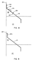
- the baffle 10 carries an end bracket 18, integrally depending from and, in the most preferred form, unitarily fabricated on the second end 16 of the panel member 12 for securing the panel to the radially inward facing surface of the peripheral wall 20 of a clarifier tank 22 (see Figs. 8 and 9).
- the second or opposite end 16 of the baffle 10 is adopted for securement to the end bracket 18 of a next-adjacent baffle member when a plurality of such baffles are interconnectedly engaged, as hereinafter described, to form a vented baffle system in accordance with the invention and, for that purpose, may have one or a plurality of bores defined there through for receiving rivets or the like fasteners attaching the adjacent baffles one to the other.
- the baffle 10 also includes relief valve means 24 such as a diaphragm 24a which is provided near the top of each panel member 12.
- the diaphragm 24a when diaphragm 24a is provided, the diaphragm 24a itself, is stiff and provides the necessary force to resist opening until the appropriate pressure is reached.
- the diaphragm 24a may be positioned on the upper portion of the panel member 12. Typically, a hole or slot (not shown) is cut into the panel member 12. In this way, the diaphragm 24a may be inserted into the hole or slot of the panel member 12.
- the panel member 12 is shown as downwardly sloping from the peripheral tank wall 20 toward the interior of the tank 22 and the tank bottom (not shown).
- the panel member 12 has a lower side 26 and an upper side 28.
- the panel member 12 extends downwardly from an upper edge 30 which optionally may be secured to the peripheral tank wall 20 with a mounting flange.
- the panel member 12 defines a space 32 formed between the junction of the lower side of the panel member 26 and the peripheral tank wall 20.
- the diaphragm 24a is mounted in the panel member 12 and is in fluid communication with the space 32 located between the junction of the lower side 26 of the panel member 12 and the peripheral tank wall 20 for venting the pressure in space 32.
- the diaphragm 24a is fabricated from neoprene or other suitable material which is impervious to the submerged waste water environment.
- the diaphragm 24a itself, is stiff and provides the necessary force to resist opening until the appropriate pressure is reached.
- the diaphragm 24a is a positionable in a first open position when the pressure exerted by the build up of gas reaches a predetermined level and positionable in a second closed position when the pressure exerted by the build up of gas reaches a second predetermined level.
- a further embodiment of the relief valve means 24 is shown in Figs. 4 and 5 which is not according to the invention.
- the panel member 12 is also shown as downwardly sloping from the peripheral tank wall 20 toward the interior of the tank 22 and the tank bottom (not shown). Similar to the embodiment shown in Fig. 1, the panel member 12 has a lower side 26 and an upper side 28.
- a relief valve 24b is mounted in the panel member 12 and is in fluid communication with the space 32 located between the junction of the lower side 26 of panel member 12 and the peripheral tank wall 20 preventing the pressure in space 32.
- the relief valve 24b is spring loaded via a spring mechanism 34 and is attached to a guide wire 46. Accordingly, the spring mechanism 34 and guide wire 46 provide the necessary force to resist opening until the proper pressure is reached. Thereafter, the spring biased relief valve 24b is closed.
- the spring biased relief valve 24b consists of a housing 36 which is mounted in a hole or slot (not shown) cut into the panel member 12. Securement of the housing 36 to the panel member 12 is provided with rivets, fasteners, screws or the like 38. In this way, flap 40 may be positionable in both a first open position and a second closed position depending on the pressure in space 32.
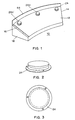
- a relief conduit 24c is shown which is provided near the top of the panel member 12.
- the conduit 24c vents the pressure exerted by the buildup of gas which accumulates in the space 32 formed between the junction of the lower side of the panel member 26 and the peripheral tank wall 20.
- the conduit 24c is in fluid communication with the space 32 located between the junction of the lower side 26 of the panel member 12 and the peripheral tank wall 20 for venting the pressure in the space.
- the relief conduit 24c may be provided with a venting flap 42.
- This venting flap 42 is positionable in a first open position when the pressure exerted by the buildup of gas reaches a predetermined level and positionable in a second closed position when the pressure exerted by the buildup of gas reaches a second predetermined level.
- One or more relief conduits 24c may be provided with each baffle member 10.
- the relief conduit 24c is integrally molded in the mounting flange 44. In this way, the venting conduits 24c provide continuous venting of the pressure in the space 32 formed between the junction of the lower side of the panel member and the peripheral tank wall thereby alleviating the buildup of pressure in the space 32.
- the vented baffle system of the present invention is formed using a plurality of the individual vented baffle members and as will now be described with reference, by way of example, to figures 6 and 9.
- the first plural members are interconnected and attached in an end-to-end arrangement so that the panels 12 form a smoothly continuous downwardly and inwardly (i.e., toward the center or central portion of the clarifying tank 22) sloping surface.
- the panel defined sloping surface extends outwardly from the peripheral tank wall 20, to which the baffle members 10 are supportedly mounted, toward the tank bottom and terminates in and in spaced relation at a suitable distance from the tank bottom.
- the baffle members 12 define a cantilevered surface supported throughout the direct securement at its top to the tank wall 20 and through indirect attachment, by way of the end brackets 18 at intervals along the sloping surface as defined by the lateral ends of the panel members 10.
- the individual baffle members 10 are additionally secured to the clarifier tank wall, as by rivets or screws or other fasteners or the like, at and through the mounting flange 44 and, when optionally present, a supplemental flange (not shown).
Landscapes
- Chemical & Material Sciences (AREA)
- Chemical Kinetics & Catalysis (AREA)
- Health & Medical Sciences (AREA)
- Toxicology (AREA)
- Safety Valves (AREA)
- Filling Or Discharging Of Gas Storage Vessels (AREA)
- Glass Compositions (AREA)
- Apparatus For Radiation Diagnosis (AREA)
- Led Device Packages (AREA)
- Sewage (AREA)
- Heat-Exchange Devices With Radiators And Conduit Assemblies (AREA)
Claims (7)
- Système comprenant une pluralité de déflecteurs (10) agencés dans un réservoir d'épuration (22) afin de séparer par gravitation des solides en suspension dans un liquide contenu dans le réservoir, le réservoir d'épuration comportant un fond et une paroi périphérique sensiblement verticale qui délimite l'intérieur du réservoir qui contient le liquide, ledit déflecteur (10) comprenant :caractérisée en ce que le système comprend en outre :un élément en forme de panneau (12) en pente descendante depuis la paroi périphérique du réservoir en direction de l'intérieur du réservoir et du fond du réservoir, ledit élément de panneau (12) présentant un côté inférieur (26) et un côté supérieur (28), ledit élément de panneau (12) s'étendant vers le bas depuis un bord supérieur (30) jusqu'à un bord inférieur disposé en relation d'écartement par rapport au fond du réservoir, ledit élément de panneau (12) ayant un premier côté latéral (16) et un deuxième côté latéral (14), ledit élément de panneau (12) définissant un espace (32) formé entre la jonction du côté inférieur (26) de l'élément de panneau (12) et la paroi périphérique (20) du réservoir ;une platine d'extrémité (18) destinée à être attachée sur ledit premier côté latéral (16) dudit élément de panneau (12) afin de fixer ledit élément de panneau (12) en le supportant sur la paroi périphérique (20) du réservoir d'épuration (22) ;une bride de montage (44) qui s'étend de façon intégrale depuis le bord supérieur (30) dudit élément de panneau (12) et fixée sur la paroi périphérique (20) afin de fixer ledit élément de panneau (12) sur la paroi périphérique (20) du réservoir d'épuration (22), ladite bride de montage (44) étant pourvue d'un bord supérieur,un conduit d'échappement (24c) moulé de façon intégrale dans ladite bride de montage (44) et en communication hydraulique avec ledit espace (32) formé entre la jonction du côté inférieur (26) de l'élément de panneau (12) et la paroi périphérique (20) du réservoir afin de laisser échapper la pression dans ledit espace (32), ledit conduit d'échappement (24c) ayant une première extrémité d'entrée proche dudit bord supérieur (30) dudit élément de panneau (12) et une deuxième extrémité de sortie proche dudit bord supérieur (30) de ladite bride de montage (44).
- Système selon la revendication 1, dans lequel la paroi périphérique (20) du réservoir d'épuration (22) présente un rayon de courbure, et dans lequel ledit bord supérieur (30) de l'élément de panneau présente un rayon de courbure qui correspond au rayon de courbure du réservoir d'épuration (22).
- Système selon la revendication 1, dans lequel chaque déflecteur (10) comprend en outre une bride de rigidification qui dépend de façon unitaire depuis ledit bord inférieur dudit élément de panneau (12) pour procurer une rigidité renforcée audit élément de panneau (12).
- Système selon la revendication 1, dans lequel ladite platine d'extrémité (18) comprend en outre une bride de montage susceptible d'être fixée sur la paroi périphérique (20) du réservoir en engagement surface-contre-surface pour fixer ladite platine d'extrémité (18) sur la paroi périphérique (20), et une surface de montage pour recevoir le premier côté latéral (16) de l'élément de panneau (12) du déflecteur adjacent suivant parmi ladite pluralité de déflecteurs, de manière à fixer ensemble des baffles adjacents.
- Système selon la revendication 1, dans lequel ledit élément de panneau (12) définit un plan régulièrement continu, et ladite surface de montage de ladite platine d'extrémité (18) est en évidement depuis ledit plan, de sorte que lorsque le premier côté latéral d'un élément de panneau de l'un des déflecteurs de ladite pluralité de déflecteurs est fixé sur la platine terminale du déflecteur adjacent suivant de ladite pluralité de déflecteurs, les éléments de panneau du déflecteur et du déflecteur adjacent suivant forment une surface régulière continue en pente descendante.
- Système selon la revendication 1, dans lequel la paroi périphérique (20) du réservoir d'épuration (22) présente un rayon de courbure, dans lequel ledit élément de panneau (12) comporte un bord supérieur (30), et dans lequel ledit bord supérieur (30) de l'élément de panneau présente un rayon de courbure qui correspond au rayon de courbure du réservoir d'épuration (22).
- Système selon la revendication 1, dans lequel ledit déflecteur (10) est moulé sous forme d'une unité d'une seule pièce en composite renforcé de fibres de verre.
Applications Claiming Priority (3)
| Application Number | Priority Date | Filing Date | Title |
|---|---|---|---|
| US08/374,328 US5597483A (en) | 1995-01-18 | 1995-01-18 | Vented baffle system |
| US374328 | 1995-01-18 | ||
| PCT/US1996/000535 WO1996022142A1 (fr) | 1995-01-18 | 1996-01-17 | Systeme a deflecteurs a events |
Publications (3)
| Publication Number | Publication Date |
|---|---|
| EP0804267A1 EP0804267A1 (fr) | 1997-11-05 |
| EP0804267A4 EP0804267A4 (fr) | 1998-06-10 |
| EP0804267B1 true EP0804267B1 (fr) | 2001-12-12 |
Family
ID=23476307
Family Applications (1)
| Application Number | Title | Priority Date | Filing Date |
|---|---|---|---|
| EP96905152A Expired - Lifetime EP0804267B1 (fr) | 1995-01-18 | 1996-01-17 | Systeme a deflecteurs a events |
Country Status (7)
| Country | Link |
|---|---|
| US (1) | US5597483A (fr) |
| EP (1) | EP0804267B1 (fr) |
| JP (1) | JP3408542B2 (fr) |
| AT (1) | ATE210483T1 (fr) |
| AU (1) | AU4898596A (fr) |
| DE (1) | DE69617904T2 (fr) |
| WO (1) | WO1996022142A1 (fr) |
Families Citing this family (17)
| Publication number | Priority date | Publication date | Assignee | Title |
|---|---|---|---|---|
| US6712222B2 (en) * | 2002-07-29 | 2004-03-30 | Earle Schaller | Integrated scum baffle and launder cover for use in a clarifier tank |
| US7416662B2 (en) * | 2005-11-28 | 2008-08-26 | Molded Fiber Glass Water Treatment Products Co. | Corrugated density baffle |
| KR20070079204A (ko) * | 2006-02-01 | 2007-08-06 | 삼성전자주식회사 | 광학판의 제조방법, 이에 의한 광학판 및 광학판을포함하는 액정표시장치 |
| US7556157B2 (en) * | 2007-02-02 | 2009-07-07 | Earle Schaller | Density current baffle for a clarifier tank |
| US7473358B1 (en) * | 2007-06-29 | 2009-01-06 | Earle Schaller | Hinged cover for use in a clarifier tank having an inboard launder channel |
| US7963403B2 (en) * | 2008-04-23 | 2011-06-21 | Earle Schaller | Dual surface density baffle for clarifier tank |
| US7971731B2 (en) * | 2008-10-15 | 2011-07-05 | Earle Schaller | Density baffle for clarifier tank |
| US9339742B2 (en) * | 2011-02-09 | 2016-05-17 | Earle Schaller | Density current baffle for a clarifier tank |
| CA2734811C (fr) * | 2011-03-29 | 2012-11-20 | Imperial Oil Resources Limited | Puits d'alimentation pour recipient de separation |
| CA2792901C (fr) * | 2011-10-21 | 2019-05-07 | Shell Canada Energy | Distributeur d'alimentation de decanteur de traitement de mousse de bitume |
| ITUD20130026A1 (it) * | 2013-02-26 | 2014-08-27 | Leandro Taboga | Sistema integrato di depurazione biologica per liquidi basato sull' abbinamento di biomassa batterica e vegetale comprendente lo stadio di addensamento e di stabilizzazione dei fanghi. |
| US20150060346A1 (en) * | 2013-08-30 | 2015-03-05 | Brentwood Industries, Inc. | Hood for Preventing the Discharge of Debris from a Wastewater Collection Basin |
| CA2980164C (fr) | 2015-03-19 | 2021-02-16 | Paterson & Cooke Ideas, Ltd. | Distributeur d'alimentation d'epaississant |
| US9919244B2 (en) | 2016-03-07 | 2018-03-20 | Ovivo Inc. | Submerged clarifier launder |
| WO2018094103A1 (fr) * | 2016-11-17 | 2018-05-24 | Paterson & Cooke Ideas, Ltd. | Système de dilution d'alimentation d'épaississant |
| US10722823B2 (en) * | 2018-08-08 | 2020-07-28 | Nefco Systems, Inc. | Vented baffle for clarifier tank |
| US11148073B2 (en) * | 2019-09-09 | 2021-10-19 | Environetics, Inc. | Tensile structure density current baffle |
Family Cites Families (19)
| Publication number | Priority date | Publication date | Assignee | Title |
|---|---|---|---|---|
| US2150157A (en) * | 1939-03-14 | Dtjstproof ventilator | ||
| US707567A (en) * | 1902-03-31 | 1902-08-26 | Eugene R Edson | Rendering apparatus. |
| US2422394A (en) * | 1945-08-03 | 1947-06-17 | Carter Ralph B Co | Method of digesting sludge arranged at different levels and apparatus therefor |
| US2790372A (en) * | 1953-03-30 | 1957-04-30 | Eugene R Cooper | Damper assembly |
| US2826306A (en) * | 1953-09-10 | 1958-03-11 | Phillips Petroleum Co | Water-organic separator tank |
| US3184065A (en) * | 1961-12-29 | 1965-05-18 | Shell Oil Co | Settler |
| AT300687B (de) * | 1970-07-13 | 1972-08-10 | Internat Pollution Control Sys | Vorrichtung zur Abtrennung von Öl aus verölten Flüssigkeiten, insbesondere Schiffsbilgen von Sportbooten od.dgl. |
| US4109433A (en) * | 1977-07-13 | 1978-08-29 | Maze Perry V | Below roof ventilator |
| NL7711963A (nl) * | 1977-10-31 | 1979-05-02 | Ballast Nedam Groep Nv | Afscheidingsinrichting. |
| US4391704A (en) * | 1981-07-28 | 1983-07-05 | Fischer & Porter Company | Gas-extraction arrangement for wastewater settling tank |
| US4899505A (en) * | 1982-09-13 | 1990-02-13 | Keith Muters | Roof ventilator |
| GB8302108D0 (en) * | 1983-01-26 | 1983-03-02 | Ventana Ltd | Ventilators |
| NL8601120A (nl) * | 1986-05-01 | 1987-12-01 | Pacques Bv | Inrichting voor de anaerobe zuivering van afvalwater. |
| US4710292A (en) * | 1986-08-18 | 1987-12-01 | Atara Corporation | Digester tank with foam control cover |
| US4706418A (en) * | 1986-08-26 | 1987-11-17 | Industrial Research Development, Inc. | Roofing cant |
| US4767536A (en) * | 1987-08-27 | 1988-08-30 | Warminster Fiberglass Company | Gas extraction outlet for wastewater settling tank |
| JPH0614821B2 (ja) * | 1988-10-14 | 1994-03-02 | 有限会社パラサイト | 多重気相沈澱槽 |
| US5227077A (en) * | 1992-02-26 | 1993-07-13 | Baker Hughes Incorporated | Launder with baffle system for recovering filtration media in solution |
| US5252205A (en) * | 1992-09-11 | 1993-10-12 | Earle Schaller | Unitary clarifier baffle and integrated baffle system |
-
1995
- 1995-01-18 US US08/374,328 patent/US5597483A/en not_active Expired - Lifetime
-
1996
- 1996-01-17 DE DE69617904T patent/DE69617904T2/de not_active Expired - Lifetime
- 1996-01-17 WO PCT/US1996/000535 patent/WO1996022142A1/fr not_active Ceased
- 1996-01-17 AT AT96905152T patent/ATE210483T1/de not_active IP Right Cessation
- 1996-01-17 EP EP96905152A patent/EP0804267B1/fr not_active Expired - Lifetime
- 1996-01-17 AU AU48985/96A patent/AU4898596A/en not_active Abandoned
- 1996-01-17 JP JP52234696A patent/JP3408542B2/ja not_active Expired - Lifetime
Also Published As
| Publication number | Publication date |
|---|---|
| WO1996022142A1 (fr) | 1996-07-25 |
| EP0804267A4 (fr) | 1998-06-10 |
| AU4898596A (en) | 1996-08-07 |
| JPH10512490A (ja) | 1998-12-02 |
| ATE210483T1 (de) | 2001-12-15 |
| DE69617904T2 (de) | 2002-08-22 |
| EP0804267A1 (fr) | 1997-11-05 |
| US5597483A (en) | 1997-01-28 |
| DE69617904D1 (de) | 2002-01-24 |
| JP3408542B2 (ja) | 2003-05-19 |
Similar Documents
| Publication | Publication Date | Title |
|---|---|---|
| EP0804267B1 (fr) | Systeme a deflecteurs a events | |
| CA2100380C (fr) | Chicane pour reservoir de clarification et systeme de chicanes integrees | |
| WO1996022142B1 (fr) | Systeme a deflecteurs a events | |
| US9932247B1 (en) | Passive grease trap using separator technology | |
| US7556157B2 (en) | Density current baffle for a clarifier tank | |
| US4487692A (en) | Sidewall mounted separator for removing solids in waste water | |
| US4059529A (en) | Baffle for water or sewage settling tanks | |
| US20250052047A1 (en) | Waste collection and disposal system for toilets | |
| US6015488A (en) | Filter system for septic tank | |
| US7416662B2 (en) | Corrugated density baffle | |
| US10722823B2 (en) | Vented baffle for clarifier tank | |
| US20090294352A1 (en) | Integrated perforated flocculating baffle system | |
| WO1999042194A1 (fr) | Systeme et procede de separation des constituants lourds et legers melanges d'un courant de liquide | |
| US5038418A (en) | Bathroom waste collection and disposal unit | |
| WO2008070696A1 (fr) | Appareil de traitement de l'eau et paroi pour clarificateur | |
| US7468128B2 (en) | Bilge water barrier and pollution prevention system | |
| JPH06510480A (ja) | 円形槽から浄化廃水を取り出す装置 | |
| JP2006181434A (ja) | 濾過ユニット | |
| JP3228561B2 (ja) | 洗浄可能な組立式床構造 | |
| CN223409459U (zh) | 一种反硝化-硝化污水处理装置 | |
| US20250296017A1 (en) | Separator for separating solids from a fluid | |
| GB2217767A (en) | Air vent of fabricated tank | |
| EP4417507A1 (fr) | Barrage d'humidité de protection dans un ensemble cabine d'aéronef | |
| EP0048158A2 (fr) | Réservoir d'interception | |
| US7524412B2 (en) | Apparatus for removing fluid from bilge of a marine vessel |
Legal Events
| Date | Code | Title | Description |
|---|---|---|---|
| PUAI | Public reference made under article 153(3) epc to a published international application that has entered the european phase |
Free format text: ORIGINAL CODE: 0009012 |
|
| 17P | Request for examination filed |
Effective date: 19970703 |
|
| AK | Designated contracting states |
Kind code of ref document: A1 Designated state(s): AT BE CH DE DK ES FR GB GR IE IT LI LU MC NL PT SE |
|
| A4 | Supplementary search report drawn up and despatched |
Effective date: 19980424 |
|
| AK | Designated contracting states |
Kind code of ref document: A4 Designated state(s): AT BE CH DE DK ES FR GB GR IE IT LI LU MC NL PT SE |
|
| 17Q | First examination report despatched |
Effective date: 20000113 |
|
| GRAG | Despatch of communication of intention to grant |
Free format text: ORIGINAL CODE: EPIDOS AGRA |
|
| GRAG | Despatch of communication of intention to grant |
Free format text: ORIGINAL CODE: EPIDOS AGRA |
|
| GRAH | Despatch of communication of intention to grant a patent |
Free format text: ORIGINAL CODE: EPIDOS IGRA |
|
| GRAH | Despatch of communication of intention to grant a patent |
Free format text: ORIGINAL CODE: EPIDOS IGRA |
|
| GRAA | (expected) grant |
Free format text: ORIGINAL CODE: 0009210 |
|
| AK | Designated contracting states |
Kind code of ref document: B1 Designated state(s): AT BE CH DE DK ES FR GB GR IE IT LI LU MC NL PT SE |
|
| PG25 | Lapsed in a contracting state [announced via postgrant information from national office to epo] |
Ref country code: NL Free format text: LAPSE BECAUSE OF FAILURE TO SUBMIT A TRANSLATION OF THE DESCRIPTION OR TO PAY THE FEE WITHIN THE PRESCRIBED TIME-LIMIT Effective date: 20011212 Ref country code: LI Free format text: LAPSE BECAUSE OF FAILURE TO SUBMIT A TRANSLATION OF THE DESCRIPTION OR TO PAY THE FEE WITHIN THE PRESCRIBED TIME-LIMIT Effective date: 20011212 Ref country code: GR Free format text: LAPSE BECAUSE OF FAILURE TO SUBMIT A TRANSLATION OF THE DESCRIPTION OR TO PAY THE FEE WITHIN THE PRESCRIBED TIME-LIMIT Effective date: 20011212 Ref country code: CH Free format text: LAPSE BECAUSE OF FAILURE TO SUBMIT A TRANSLATION OF THE DESCRIPTION OR TO PAY THE FEE WITHIN THE PRESCRIBED TIME-LIMIT Effective date: 20011212 Ref country code: BE Free format text: LAPSE BECAUSE OF FAILURE TO SUBMIT A TRANSLATION OF THE DESCRIPTION OR TO PAY THE FEE WITHIN THE PRESCRIBED TIME-LIMIT Effective date: 20011212 Ref country code: AT Free format text: LAPSE BECAUSE OF FAILURE TO SUBMIT A TRANSLATION OF THE DESCRIPTION OR TO PAY THE FEE WITHIN THE PRESCRIBED TIME-LIMIT Effective date: 20011212 |
|
| REF | Corresponds to: |
Ref document number: 210483 Country of ref document: AT Date of ref document: 20011215 Kind code of ref document: T |
|
| REG | Reference to a national code |
Ref country code: CH Ref legal event code: EP |
|
| REG | Reference to a national code |
Ref country code: GB Ref legal event code: IF02 |
|
| PG25 | Lapsed in a contracting state [announced via postgrant information from national office to epo] |
Ref country code: LU Free format text: LAPSE BECAUSE OF NON-PAYMENT OF DUE FEES Effective date: 20020117 Ref country code: IE Free format text: LAPSE BECAUSE OF NON-PAYMENT OF DUE FEES Effective date: 20020117 |
|
| REG | Reference to a national code |
Ref country code: IE Ref legal event code: FG4D |
|
| REF | Corresponds to: |
Ref document number: 69617904 Country of ref document: DE Date of ref document: 20020124 |
|
| PG25 | Lapsed in a contracting state [announced via postgrant information from national office to epo] |
Ref country code: SE Free format text: LAPSE BECAUSE OF FAILURE TO SUBMIT A TRANSLATION OF THE DESCRIPTION OR TO PAY THE FEE WITHIN THE PRESCRIBED TIME-LIMIT Effective date: 20020312 Ref country code: PT Free format text: LAPSE BECAUSE OF FAILURE TO SUBMIT A TRANSLATION OF THE DESCRIPTION OR TO PAY THE FEE WITHIN THE PRESCRIBED TIME-LIMIT Effective date: 20020312 Ref country code: DK Free format text: LAPSE BECAUSE OF FAILURE TO SUBMIT A TRANSLATION OF THE DESCRIPTION OR TO PAY THE FEE WITHIN THE PRESCRIBED TIME-LIMIT Effective date: 20020312 |
|
| ET | Fr: translation filed | ||
| NLV1 | Nl: lapsed or annulled due to failure to fulfill the requirements of art. 29p and 29m of the patents act | ||
| REG | Reference to a national code |
Ref country code: CH Ref legal event code: PL |
|
| PG25 | Lapsed in a contracting state [announced via postgrant information from national office to epo] |
Ref country code: ES Free format text: LAPSE BECAUSE OF FAILURE TO SUBMIT A TRANSLATION OF THE DESCRIPTION OR TO PAY THE FEE WITHIN THE PRESCRIBED TIME-LIMIT Effective date: 20020627 |
|
| PG25 | Lapsed in a contracting state [announced via postgrant information from national office to epo] |
Ref country code: MC Free format text: LAPSE BECAUSE OF NON-PAYMENT OF DUE FEES Effective date: 20020801 |
|
| PLBE | No opposition filed within time limit |
Free format text: ORIGINAL CODE: 0009261 |
|
| STAA | Information on the status of an ep patent application or granted ep patent |
Free format text: STATUS: NO OPPOSITION FILED WITHIN TIME LIMIT |
|
| REG | Reference to a national code |
Ref country code: IE Ref legal event code: MM4A |
|
| 26N | No opposition filed | ||
| NLV1 | Nl: lapsed or annulled due to failure to fulfill the requirements of art. 29p and 29m of the patents act | ||
| PGFP | Annual fee paid to national office [announced via postgrant information from national office to epo] |
Ref country code: FR Payment date: 20120209 Year of fee payment: 17 |
|
| PGFP | Annual fee paid to national office [announced via postgrant information from national office to epo] |
Ref country code: IT Payment date: 20120120 Year of fee payment: 17 |
|
| PGFP | Annual fee paid to national office [announced via postgrant information from national office to epo] |
Ref country code: GB Payment date: 20130122 Year of fee payment: 18 |
|
| PGFP | Annual fee paid to national office [announced via postgrant information from national office to epo] |
Ref country code: DE Payment date: 20130328 Year of fee payment: 18 |
|
| REG | Reference to a national code |
Ref country code: FR Ref legal event code: ST Effective date: 20130930 |
|
| PG25 | Lapsed in a contracting state [announced via postgrant information from national office to epo] |
Ref country code: FR Free format text: LAPSE BECAUSE OF NON-PAYMENT OF DUE FEES Effective date: 20130131 |
|
| PG25 | Lapsed in a contracting state [announced via postgrant information from national office to epo] |
Ref country code: IT Free format text: LAPSE BECAUSE OF NON-PAYMENT OF DUE FEES Effective date: 20130117 |
|
| REG | Reference to a national code |
Ref country code: DE Ref legal event code: R119 Ref document number: 69617904 Country of ref document: DE |
|
| GBPC | Gb: european patent ceased through non-payment of renewal fee |
Effective date: 20140117 |
|
| REG | Reference to a national code |
Ref country code: DE Ref legal event code: R119 Ref document number: 69617904 Country of ref document: DE Effective date: 20140801 |
|
| PG25 | Lapsed in a contracting state [announced via postgrant information from national office to epo] |
Ref country code: DE Free format text: LAPSE BECAUSE OF NON-PAYMENT OF DUE FEES Effective date: 20140801 |
|
| PG25 | Lapsed in a contracting state [announced via postgrant information from national office to epo] |
Ref country code: GB Free format text: LAPSE BECAUSE OF NON-PAYMENT OF DUE FEES Effective date: 20140117 |