EP0804330B1 - Werkzeug zum formen oder spritzen plastischer massen und formzubehör, insbesondere auswerfeinrichtung oder kernstifteinrichtung für ein derartiges werkzeug - Google Patents
Werkzeug zum formen oder spritzen plastischer massen und formzubehör, insbesondere auswerfeinrichtung oder kernstifteinrichtung für ein derartiges werkzeug Download PDFInfo
- Publication number
- EP0804330B1 EP0804330B1 EP95915789A EP95915789A EP0804330B1 EP 0804330 B1 EP0804330 B1 EP 0804330B1 EP 95915789 A EP95915789 A EP 95915789A EP 95915789 A EP95915789 A EP 95915789A EP 0804330 B1 EP0804330 B1 EP 0804330B1
- Authority
- EP
- European Patent Office
- Prior art keywords
- molding
- mold
- tool
- ejector
- unit
- Prior art date
- Legal status (The legal status is an assumption and is not a legal conclusion. Google has not performed a legal analysis and makes no representation as to the accuracy of the status listed.)
- Expired - Lifetime
Links
Images

Classifications
-
- B—PERFORMING OPERATIONS; TRANSPORTING
- B29—WORKING OF PLASTICS; WORKING OF SUBSTANCES IN A PLASTIC STATE IN GENERAL
- B29C—SHAPING OR JOINING OF PLASTICS; SHAPING OF MATERIAL IN A PLASTIC STATE, NOT OTHERWISE PROVIDED FOR; AFTER-TREATMENT OF THE SHAPED PRODUCTS, e.g. REPAIRING
- B29C45/00—Injection moulding, i.e. forcing the required volume of moulding material through a nozzle into a closed mould; Apparatus therefor
- B29C45/17—Component parts, details or accessories; Auxiliary operations
- B29C45/26—Moulds
- B29C45/37—Mould cavity walls, i.e. the inner surface forming the mould cavity, e.g. linings
- B29C45/372—Mould cavity walls, i.e. the inner surface forming the mould cavity, e.g. linings provided with means for marking or patterning, e.g. numbering articles
-
- B—PERFORMING OPERATIONS; TRANSPORTING
- B29—WORKING OF PLASTICS; WORKING OF SUBSTANCES IN A PLASTIC STATE IN GENERAL
- B29C—SHAPING OR JOINING OF PLASTICS; SHAPING OF MATERIAL IN A PLASTIC STATE, NOT OTHERWISE PROVIDED FOR; AFTER-TREATMENT OF THE SHAPED PRODUCTS, e.g. REPAIRING
- B29C33/00—Moulds or cores; Details thereof or accessories therefor
- B29C33/42—Moulds or cores; Details thereof or accessories therefor characterised by the shape of the moulding surface, e.g. ribs or grooves
- B29C33/424—Moulding surfaces provided with means for marking or patterning
-
- B—PERFORMING OPERATIONS; TRANSPORTING
- B29—WORKING OF PLASTICS; WORKING OF SUBSTANCES IN A PLASTIC STATE IN GENERAL
- B29C—SHAPING OR JOINING OF PLASTICS; SHAPING OF MATERIAL IN A PLASTIC STATE, NOT OTHERWISE PROVIDED FOR; AFTER-TREATMENT OF THE SHAPED PRODUCTS, e.g. REPAIRING
- B29C33/00—Moulds or cores; Details thereof or accessories therefor
- B29C33/44—Moulds or cores; Details thereof or accessories therefor with means for, or specially constructed to facilitate, the removal of articles, e.g. of undercut articles
- B29C33/442—Moulds or cores; Details thereof or accessories therefor with means for, or specially constructed to facilitate, the removal of articles, e.g. of undercut articles with mechanical ejector or drive means therefor
-
- B—PERFORMING OPERATIONS; TRANSPORTING
- B29—WORKING OF PLASTICS; WORKING OF SUBSTANCES IN A PLASTIC STATE IN GENERAL
- B29C—SHAPING OR JOINING OF PLASTICS; SHAPING OF MATERIAL IN A PLASTIC STATE, NOT OTHERWISE PROVIDED FOR; AFTER-TREATMENT OF THE SHAPED PRODUCTS, e.g. REPAIRING
- B29C45/00—Injection moulding, i.e. forcing the required volume of moulding material through a nozzle into a closed mould; Apparatus therefor
- B29C45/17—Component parts, details or accessories; Auxiliary operations
- B29C45/40—Removing or ejecting moulded articles
- B29C45/4005—Ejector constructions; Ejector operating mechanisms
- B29C45/401—Ejector pin constructions or mountings
-
- B—PERFORMING OPERATIONS; TRANSPORTING
- B29—WORKING OF PLASTICS; WORKING OF SUBSTANCES IN A PLASTIC STATE IN GENERAL
- B29C—SHAPING OR JOINING OF PLASTICS; SHAPING OF MATERIAL IN A PLASTIC STATE, NOT OTHERWISE PROVIDED FOR; AFTER-TREATMENT OF THE SHAPED PRODUCTS, e.g. REPAIRING
- B29C37/00—Component parts, details, accessories or auxiliary operations, not covered by group B29C33/00 or B29C35/00
- B29C2037/80—Identifying, e.g. coding, dating, marking, numbering
Definitions
- the present invention relates to a mold accessory device, namely ejector device or core pin device for a tool for molding or injection molding plastic masses, the device in the during molding or Spraying the plastic mass facing end area Has marking unit.
- Molded parts are known, for example in the wall to insert a marking stamp of an injection mold, the marking on the surface of the mold structured application.
- the marking can, for example, in a material specification or a date specification.
- FR-A-2.644.610 shows an automatic device Numbering of injection molded parts. With this device a groove-shaped marking on the appropriate injection molded part applied. At the same time Area next to the mold accessory on the tool Marking must be attached.
- the invention is the technical problem or the task based on a mold accessories, namely ejector or core pin device, for a tool for To specify forms or injections of plastic masses is versatile, the respective installation constellation is adaptable and ensures reliable marking.
- the device according to the invention is characterized by the features of given independent claim 1. Advantageous configurations and further training are the subject of the dependent Expectations.
- the device according to the invention for a mold or injection of plastic masses stands out accordingly characterized in that the marking unit releasably on the mold accessories is attachable.
- a particularly advantageous embodiment is distinguished characterized in that the marking unit as a date stamp is trained.
- a particularly preferred embodiment is characterized by this from that the ejector device is designed as an ejector pin is.
- Mold accessories is this as an ejector pin with a the plastic mass installed state facing first End area and one opposite the first end area arranged second end region, the first End region has the marking unit.
- the marking unit can be described, for example, as Date stamp be formed.
- a particularly preferred embodiment of the invention Ejector device or core pin device which also without Marking unit can be used, it is characterized from that at the second end area a head plate by means of Fasteners can be fastened, the length of the receiving structure chosen larger for the fastener is considered to ensure adequate attachment required.
- the support structure is no longer required for different lengths ejector pins of different lengths to provide. Rather, it becomes a sufficiently large, the usual Cases covering length selected, and such an ejector pin is produced.
- a shorter ejector pin part of the ejector pin is required cut off, with the remaining construction then remaining such a great length for the fastener has that an attachment of the head plate easily possible is.
- Each user can therefore vote for the respective special application an ejector pin in the required Create length. The same applies to the core pin device.
- a preferred development of the mold accessories according to the invention is characterized in that the ejector device and / or core pin device an adapter unit with marking unit and a shaft unit with predeterminable Has length, the adapter unit detachably on the Shaft unit is attached.
- the section shown in Fig. 1 from an injection mold 20 has a lower platen 44 and an upper one Platen 50 on.
- a lower tool set 36 is arranged, the top of which has a part of the outer contour of a mold 32 to be sprayed.
- an upper one Tool set 34 is arranged, the underside of some areas is so shaped that the outer contour in some areas the form 32 forms. In the area between the lower tool insert and the upper tool insert 34 becomes the shape 18 injected via a schematically illustrated sprue.
- the sprue bush with the further course of the sprue is not shown in Fig. 1.
- An intermediate plate is located above the upper tool insert 34 46 available. Between the intermediate plate 46 and the an upper ejector plate 50, an ejector plate pack 48 is arranged, the to an ejector plunger, not shown is connected and moved by the ejector stroke A. can be.
- An ejector pin 10 is located in the ejector plate pack 48 anchored its shaft 12 longitudinally displaceable in the intermediate plate 46 and the upper tool insert 34 is guided.
- the lower end region of the ejector pin 10 is located in the immediate vicinity of the lower outer contour of the upper Tool insert 34 and comes with the injected plastic Mass in contact.
- the ejector pin 10 has the function of the injection part 32 demould after their manufacture. After the injection molding compound has been introduced into the mold 32, the lower Tool insert 36 and upper tool insert 34 moved apart. That then still adheres to the upper tool insert 34 Injection part 32 is by moving the ejector pin 10, caused by the sliding movement of the not shown ejector plunger to the ejector stroke A of the upper tool insert 34 released.
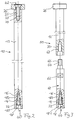
- the ejector pin 10 has one first end region 40, in the area of the injection mold 32 is arranged.
- the opposite second end region 42 is anchored in the ejector plate pack 48.
- a stepped bore 14 in the area of the smaller diameter has an internal thread.
- a marking unit preferably a Date stamp 18, screwed in accordingly.
- the placement has a head region 18.1, the outer end face of which is to be embossed Data carries, and a shaft area 18.2. in the The area of the stepped bore 14 is around the shaft area 18.2 partially arranged a compression spring 22 which opposes supports the head region 18.1 and the step of the stepped bore 14, so that the head region 18.1 resiliently supported is.
- the second end region 42 there is a blind hole 24 with a thread 25 present in the shaft 12 of the ejector pin 10.
- a head plate is placed on the end face of the second end region 42 26 arranged by means of a countersunk screw 28 on the Shank 12 is attachable.
- the blind hole 24 with her Thread 25 has a length that is greater than the length of the thread of the countersunk screw 28.
- the ejector pin 80 shown schematically in FIG. 3 differs differs from the ejector pin 10 according to FIG essentially in that it has a detachably connectable to the shaft 12
- Has adapter part 60 on which the insert (Marking stamp) 18 is releasably attached Same components bear the same reference number and will not be repeated explained.
- the adapter part has a connection to the shaft 12 60 an integrally formed screw region 64 with an external thread 66 on that in a correspondingly axial manner on the shaft 12 In the direction of the existing recess 68 with internal thread 70 can be screwed in is.
- the adapter part 60 has a shape 62 for attaching a Wrench.
- This embodiment has the advantage that the adapter part as such with a uniform Length can be produced and at the same time by using different Components with different shaft lengths of the Shank 12 a length adjustment of the entire ejector pin 80 to the respective tool is made possible without any problems.
Landscapes
- Engineering & Computer Science (AREA)
- Mechanical Engineering (AREA)
- Manufacturing & Machinery (AREA)
- Moulds For Moulding Plastics Or The Like (AREA)
- Injection Moulding Of Plastics Or The Like (AREA)
Applications Claiming Priority (3)
| Application Number | Priority Date | Filing Date | Title |
|---|---|---|---|
| DE9406940U | 1994-04-26 | ||
| DE9406940U DE9406940U1 (de) | 1994-04-26 | 1994-04-26 | Werkzeug zum Formen oder Spritzen plastischer Massen und Formzubehör, insbesondere Auswerfeinrichtung oder Kernstifteinrichtung für ein derartiges Werkzeug |
| PCT/DE1995/000524 WO1995029049A1 (de) | 1994-04-26 | 1995-04-20 | Werkzeug zum formen oder spritzen plastischer massen und formzubehör, insbesondere auswerfeinrichtung oder kernstifteinrichtung für ein derartiges werkzeug |
Publications (2)
| Publication Number | Publication Date |
|---|---|
| EP0804330A1 EP0804330A1 (de) | 1997-11-05 |
| EP0804330B1 true EP0804330B1 (de) | 1998-12-02 |
Family
ID=6907869
Family Applications (1)
| Application Number | Title | Priority Date | Filing Date |
|---|---|---|---|
| EP95915789A Expired - Lifetime EP0804330B1 (de) | 1994-04-26 | 1995-04-20 | Werkzeug zum formen oder spritzen plastischer massen und formzubehör, insbesondere auswerfeinrichtung oder kernstifteinrichtung für ein derartiges werkzeug |
Country Status (10)
| Country | Link |
|---|---|
| US (1) | US5824350A (el) |
| EP (1) | EP0804330B1 (el) |
| AT (1) | ATE173972T1 (el) |
| AU (1) | AU695081B2 (el) |
| CA (1) | CA2188914C (el) |
| DE (2) | DE9406940U1 (el) |
| DK (1) | DK0804330T3 (el) |
| ES (1) | ES2127522T3 (el) |
| GR (1) | GR3029538T3 (el) |
| WO (1) | WO1995029049A1 (el) |
Families Citing this family (10)
| Publication number | Priority date | Publication date | Assignee | Title |
|---|---|---|---|---|
| US6308929B1 (en) * | 1998-10-22 | 2001-10-30 | Klaus A. Wieder | Mold insert |
| JP4048621B2 (ja) * | 1998-12-04 | 2008-02-20 | 双葉電子工業株式会社 | マーカ付きエジェクターピン |
| US6367765B1 (en) * | 1999-09-09 | 2002-04-09 | Klaus A. Wieder | Mold vent |
| JP2007080923A (ja) * | 2005-09-12 | 2007-03-29 | Oki Electric Ind Co Ltd | 半導体パッケージの形成方法及び半導体パッケージを形成するための金型 |
| CN1986186A (zh) * | 2005-12-23 | 2007-06-27 | 深圳富泰宏精密工业有限公司 | 模具排气结构及应用其的模具结构 |
| US20070154589A1 (en) * | 2006-01-03 | 2007-07-05 | Fields Randal L | Injection core assembly for injection molding machine tooling |
| US20080179793A1 (en) * | 2007-01-26 | 2008-07-31 | Husky Injection Molding Systems Ltd. | Ejector-Plate Actuator of a Molding System |
| US20080241310A1 (en) * | 2007-03-26 | 2008-10-02 | Chih-Yu Chen | Injection mold with a quick-change apparatus |
| CA2607397A1 (en) * | 2007-10-23 | 2009-04-23 | Husky Injection Molding Systems Ltd. | An ejector assembly for ejecting parts from a mold |
| EP4674589A1 (en) * | 2024-04-11 | 2026-01-07 | Uratani Shoji Company Ltd. | Marking device |
Family Cites Families (13)
| Publication number | Priority date | Publication date | Assignee | Title |
|---|---|---|---|---|
| DE1929875C3 (de) * | 1969-06-12 | 1973-11-15 | Freya-Plastic Franz Delbrouck Gmbh, 5757 Lendringsen | Haltevorrichtung fur em in einem Formwerkzeug auswechselbar ange ordnetes Formwandteil |
| DE2427636C3 (de) * | 1974-06-07 | 1980-03-20 | Hasco-Normalien Hasenclever & Co, 5880 Luedenscheid | Verbindunganordnung für die Auswerferei einer Spritzgieß- oder Druckgießform |
| US4137962A (en) * | 1977-07-01 | 1979-02-06 | General Motors Corporation | Apparatus for marking a mold surface |
| JPS5727736A (en) * | 1980-07-28 | 1982-02-15 | Hitachi Ltd | Injection molding method |
| JPS60155423A (ja) * | 1984-01-25 | 1985-08-15 | Matsushita Electric Works Ltd | 射出成形品の刻印法 |
| JPS60193347A (ja) * | 1984-03-15 | 1985-10-01 | Toshiba Corp | 半導体製造装置 |
| DE3509274C1 (de) * | 1985-03-15 | 1986-09-18 | HASCO-Normalien Hasenclever & Co, 5880 Lüdenscheid | Spritzgiess- oder Presswerkzeug zur Verarbeitung von Kunststoffmassen |
| DE8526599U1 (de) * | 1985-09-17 | 1985-11-14 | Opitz, Wolfgang, 8750 Aschaffenburg | Zeitraumstempel zum Einsetzen in eine Form zur Metall- oder Kunststoffverarbeitung |
| FR2644610A1 (fr) * | 1989-03-14 | 1990-09-21 | Renault | Dispositif automatique de numerotation de pieces obtenues par moulage |
| DE8911171U1 (de) * | 1989-09-19 | 1989-11-02 | HASCO-Normalien Hasenclever & Co, 5880 Lüdenscheid | Markierungseinsatz für ein Spritzgieß- oder Preßwerkzeug, insbesondere für Kunststoffmassen |
| JPH0612909Y2 (ja) * | 1989-10-18 | 1994-04-06 | 富士写真フイルム株式会社 | 射出成形用金型 |
| CH679917A5 (en) * | 1989-11-15 | 1992-05-15 | Raichle Sportschuh Ag | Data markings on e.g. injection mouldings - are produced by setting into mould tool e.g. flat plate with markings, each with sec. marking adjusted by screwdriver slot |
| DE4415583C1 (de) * | 1994-05-03 | 1995-05-24 | Opitz Gmbh | Zeitraumstempel zum Einsetzen in eine Form zur Metall- oder Kunststoffverarbeitung |
-
1994
- 1994-04-26 DE DE9406940U patent/DE9406940U1/de not_active Expired - Lifetime
-
1995
- 1995-04-20 AU AU22543/95A patent/AU695081B2/en not_active Ceased
- 1995-04-20 DK DK95915789T patent/DK0804330T3/da active
- 1995-04-20 US US08/737,087 patent/US5824350A/en not_active Expired - Lifetime
- 1995-04-20 AT AT95915789T patent/ATE173972T1/de not_active IP Right Cessation
- 1995-04-20 CA CA002188914A patent/CA2188914C/en not_active Expired - Fee Related
- 1995-04-20 EP EP95915789A patent/EP0804330B1/de not_active Expired - Lifetime
- 1995-04-20 WO PCT/DE1995/000524 patent/WO1995029049A1/de not_active Ceased
- 1995-04-20 DE DE59504449T patent/DE59504449D1/de not_active Expired - Fee Related
- 1995-04-20 ES ES95915789T patent/ES2127522T3/es not_active Expired - Lifetime
-
1999
- 1999-03-01 GR GR990400633T patent/GR3029538T3/el unknown
Also Published As
| Publication number | Publication date |
|---|---|
| CA2188914A1 (en) | 1995-11-02 |
| DK0804330T3 (da) | 1999-08-16 |
| DE59504449D1 (de) | 1999-01-14 |
| DE9406940U1 (de) | 1994-07-14 |
| CA2188914C (en) | 1999-02-02 |
| EP0804330A1 (de) | 1997-11-05 |
| GR3029538T3 (en) | 1999-06-30 |
| AU695081B2 (en) | 1998-08-06 |
| ES2127522T3 (es) | 1999-04-16 |
| ATE173972T1 (de) | 1998-12-15 |
| US5824350A (en) | 1998-10-20 |
| AU2254395A (en) | 1995-11-16 |
| WO1995029049A1 (de) | 1995-11-02 |
Similar Documents
| Publication | Publication Date | Title |
|---|---|---|
| DE3509274C1 (de) | Spritzgiess- oder Presswerkzeug zur Verarbeitung von Kunststoffmassen | |
| EP0610765B1 (de) | Scharniertopf | |
| EP0804330B1 (de) | Werkzeug zum formen oder spritzen plastischer massen und formzubehör, insbesondere auswerfeinrichtung oder kernstifteinrichtung für ein derartiges werkzeug | |
| DE69718743T2 (de) | Verfahren und Vorrichtung zur Herstellung von Bürstenkörpern für Zahnbürsten | |
| DE19730772B4 (de) | Entfernbare Markierungsvorrichtung für eine Form | |
| EP0930133B1 (de) | Kelle mit Griff | |
| DE3915732C2 (de) | Verbindungsanordnung | |
| DE3933416A1 (de) | Verfahren zum oertlich definierten, festhaftenden anbringen von kunststoff-kleinteilen an im wesentlichen aus verklebten oder kunstharzgebundenen naturfasern oder spaenen bestehenden formpressteilen | |
| EP0756919B1 (de) | Vorrichtung zum Stanzen von bandförmigem und bogenförmigem Material | |
| DE2727962C3 (de) | Möbel-Beschlagteil | |
| EP3888870B1 (de) | Verfahren zum herstellen eines scharnierteils eines brillenscharniers | |
| EP1335654B1 (de) | Verfahren zur herstellung einer abgabeeinrichtung für streichfähige produkte | |
| EP0006139B1 (de) | Zur Aufnahme einer Abdeckkappe geeignete Kreuzschlitz-Schraube und Verfahren zu ihrer Herstellung | |
| DE3523128C2 (el) | ||
| EP1787784A1 (de) | Werkzeug zur Herstellung von Bauteilen durch Spritzguß, Druckguß oder Ablegeverfahren | |
| DE102009014566B4 (de) | Werkzeuge zur Herstellung von formstabilen Produkten aus Sand | |
| DE69725919T2 (de) | Harzinjektor mit Muffel | |
| DE102020001065A1 (de) | Verfahren und Vorrichtung zur Herstellung einer Schraubverbindung zweier Bauteile mit Hilfe eines Toleranzausgleichselementes | |
| DE102007004650A1 (de) | Spritzgusswerkzeug und Herstellungsverfahren für eine Airbag-Abdeckung | |
| DE3740939A1 (de) | Kennzeichnungseinheit | |
| DE102009014569B4 (de) | Werkzeug zur Herstellung von Sandprodukten und Verfahren zur Montage eines solchen Werkzeugs | |
| DE102020116676A1 (de) | System für die Einleitung von Kraft von einem Befestigungselement in eine Kunststoffkomponente und Verfahren zur Herstellung eines Systems | |
| EP0728889A1 (de) | Verfahren zur Befestigung von Bauteilen an Hohlprofilen und dabei zu verwendende Befestigungs- und Positionierelemente | |
| DE4234326A1 (de) | Vorrichtung zum Spritzformen von Batteriekästen | |
| DE29519083U1 (de) | Positionierstiftesatz |
Legal Events
| Date | Code | Title | Description |
|---|---|---|---|
| PUAI | Public reference made under article 153(3) epc to a published international application that has entered the european phase |
Free format text: ORIGINAL CODE: 0009012 |
|
| 17P | Request for examination filed |
Effective date: 19961121 |
|
| AK | Designated contracting states |
Kind code of ref document: A1 Designated state(s): AT BE CH DE DK ES FR GB GR IE IT LI LU MC NL PT SE |
|
| GRAG | Despatch of communication of intention to grant |
Free format text: ORIGINAL CODE: EPIDOS AGRA |
|
| 17Q | First examination report despatched |
Effective date: 19971222 |
|
| GRAG | Despatch of communication of intention to grant |
Free format text: ORIGINAL CODE: EPIDOS AGRA |
|
| GRAH | Despatch of communication of intention to grant a patent |
Free format text: ORIGINAL CODE: EPIDOS IGRA |
|
| GRAH | Despatch of communication of intention to grant a patent |
Free format text: ORIGINAL CODE: EPIDOS IGRA |
|
| GRAA | (expected) grant |
Free format text: ORIGINAL CODE: 0009210 |
|
| AK | Designated contracting states |
Kind code of ref document: B1 Designated state(s): AT BE CH DE DK ES FR GB GR IE IT LI LU MC NL PT SE |
|
| REF | Corresponds to: |
Ref document number: 173972 Country of ref document: AT Date of ref document: 19981215 Kind code of ref document: T |
|
| REG | Reference to a national code |
Ref country code: CH Ref legal event code: EP |
|
| REF | Corresponds to: |
Ref document number: 59504449 Country of ref document: DE Date of ref document: 19990114 |
|
| REG | Reference to a national code |
Ref country code: IE Ref legal event code: FG4D Free format text: GERMAN |
|
| ITF | It: translation for a ep patent filed | ||
| GBT | Gb: translation of ep patent filed (gb section 77(6)(a)/1977) |
Effective date: 19990212 |
|
| ET | Fr: translation filed | ||
| REG | Reference to a national code |
Ref country code: ES Ref legal event code: FG2A Ref document number: 2127522 Country of ref document: ES Kind code of ref document: T3 |
|
| REG | Reference to a national code |
Ref country code: CH Ref legal event code: NV Representative=s name: ISLER & PEDRAZZINI AG |
|
| REG | Reference to a national code |
Ref country code: PT Ref legal event code: SC4A Free format text: AVAILABILITY OF NATIONAL TRANSLATION Effective date: 19990301 |
|
| REG | Reference to a national code |
Ref country code: DK Ref legal event code: T3 |
|
| PLBE | No opposition filed within time limit |
Free format text: ORIGINAL CODE: 0009261 |
|
| STAA | Information on the status of an ep patent application or granted ep patent |
Free format text: STATUS: NO OPPOSITION FILED WITHIN TIME LIMIT |
|
| 26N | No opposition filed | ||
| REG | Reference to a national code |
Ref country code: GB Ref legal event code: IF02 |
|
| REG | Reference to a national code |
Ref country code: CH Ref legal event code: PCAR Free format text: ISLER & PEDRAZZINI AG;POSTFACH 1772;8027 ZUERICH (CH) |
|
| PGFP | Annual fee paid to national office [announced via postgrant information from national office to epo] |
Ref country code: LU Payment date: 20080505 Year of fee payment: 14 Ref country code: ES Payment date: 20080428 Year of fee payment: 14 Ref country code: DK Payment date: 20080429 Year of fee payment: 14 Ref country code: DE Payment date: 20080602 Year of fee payment: 14 Ref country code: CH Payment date: 20080430 Year of fee payment: 14 |
|
| PGFP | Annual fee paid to national office [announced via postgrant information from national office to epo] |
Ref country code: AT Payment date: 20080402 Year of fee payment: 14 |
|
| PGFP | Annual fee paid to national office [announced via postgrant information from national office to epo] |
Ref country code: MC Payment date: 20080402 Year of fee payment: 14 Ref country code: PT Payment date: 20080402 Year of fee payment: 14 Ref country code: BE Payment date: 20080527 Year of fee payment: 14 Ref country code: IT Payment date: 20080429 Year of fee payment: 14 |
|
| PGFP | Annual fee paid to national office [announced via postgrant information from national office to epo] |
Ref country code: NL Payment date: 20080424 Year of fee payment: 14 Ref country code: SE Payment date: 20080429 Year of fee payment: 14 Ref country code: IE Payment date: 20080425 Year of fee payment: 14 |
|
| PGFP | Annual fee paid to national office [announced via postgrant information from national office to epo] |
Ref country code: FR Payment date: 20080417 Year of fee payment: 14 |
|
| PGFP | Annual fee paid to national office [announced via postgrant information from national office to epo] |
Ref country code: GB Payment date: 20080429 Year of fee payment: 14 |
|
| PGFP | Annual fee paid to national office [announced via postgrant information from national office to epo] |
Ref country code: GR Payment date: 20080430 Year of fee payment: 14 |
|
| REG | Reference to a national code |
Ref country code: PT Ref legal event code: MM4A Free format text: LAPSE DUE TO NON-PAYMENT OF FEES Effective date: 20091020 |
|
| BERE | Be: lapsed |
Owner name: *DME NORMALIEN G.M.B.H. Effective date: 20090430 |
|
| REG | Reference to a national code |
Ref country code: CH Ref legal event code: PL |
|
| REG | Reference to a national code |
Ref country code: DK Ref legal event code: EBP |
|
| EUG | Se: european patent has lapsed | ||
| GBPC | Gb: european patent ceased through non-payment of renewal fee |
Effective date: 20090420 |
|
| NLV4 | Nl: lapsed or anulled due to non-payment of the annual fee |
Effective date: 20091101 |
|
| REG | Reference to a national code |
Ref country code: FR Ref legal event code: ST Effective date: 20091231 |
|
| PG25 | Lapsed in a contracting state [announced via postgrant information from national office to epo] |
Ref country code: LI Free format text: LAPSE BECAUSE OF NON-PAYMENT OF DUE FEES Effective date: 20090430 Ref country code: DE Free format text: LAPSE BECAUSE OF NON-PAYMENT OF DUE FEES Effective date: 20091103 Ref country code: CH Free format text: LAPSE BECAUSE OF NON-PAYMENT OF DUE FEES Effective date: 20090430 Ref country code: AT Free format text: LAPSE BECAUSE OF NON-PAYMENT OF DUE FEES Effective date: 20090420 |
|
| REG | Reference to a national code |
Ref country code: IE Ref legal event code: MM4A |
|
| PG25 | Lapsed in a contracting state [announced via postgrant information from national office to epo] |
Ref country code: NL Free format text: LAPSE BECAUSE OF NON-PAYMENT OF DUE FEES Effective date: 20091101 |
|
| PG25 | Lapsed in a contracting state [announced via postgrant information from national office to epo] |
Ref country code: PT Free format text: LAPSE BECAUSE OF NON-PAYMENT OF DUE FEES Effective date: 20091020 |
|
| PG25 | Lapsed in a contracting state [announced via postgrant information from national office to epo] |
Ref country code: MC Free format text: LAPSE BECAUSE OF NON-PAYMENT OF DUE FEES Effective date: 20090430 Ref country code: IE Free format text: LAPSE BECAUSE OF NON-PAYMENT OF DUE FEES Effective date: 20090420 Ref country code: GB Free format text: LAPSE BECAUSE OF NON-PAYMENT OF DUE FEES Effective date: 20090420 Ref country code: FR Free format text: LAPSE BECAUSE OF NON-PAYMENT OF DUE FEES Effective date: 20091222 Ref country code: DK Free format text: LAPSE BECAUSE OF NON-PAYMENT OF DUE FEES Effective date: 20090430 |
|
| PG25 | Lapsed in a contracting state [announced via postgrant information from national office to epo] |
Ref country code: BE Free format text: LAPSE BECAUSE OF NON-PAYMENT OF DUE FEES Effective date: 20090430 |
|
| REG | Reference to a national code |
Ref country code: ES Ref legal event code: FD2A Effective date: 20090421 |
|
| PG25 | Lapsed in a contracting state [announced via postgrant information from national office to epo] |
Ref country code: GR Free format text: LAPSE BECAUSE OF NON-PAYMENT OF DUE FEES Effective date: 20091104 |
|
| PG25 | Lapsed in a contracting state [announced via postgrant information from national office to epo] |
Ref country code: ES Free format text: LAPSE BECAUSE OF NON-PAYMENT OF DUE FEES Effective date: 20090421 |
|
| PG25 | Lapsed in a contracting state [announced via postgrant information from national office to epo] |
Ref country code: IT Free format text: LAPSE BECAUSE OF NON-PAYMENT OF DUE FEES Effective date: 20090420 |
|
| PG25 | Lapsed in a contracting state [announced via postgrant information from national office to epo] |
Ref country code: LU Free format text: LAPSE BECAUSE OF NON-PAYMENT OF DUE FEES Effective date: 20090420 |
|
| PG25 | Lapsed in a contracting state [announced via postgrant information from national office to epo] |
Ref country code: SE Free format text: LAPSE BECAUSE OF NON-PAYMENT OF DUE FEES Effective date: 20090421 |