EP0804349B1 - Dispositif de fermeture du tuyau de remplissage du reservoir d'un vehicule - Google Patents
Dispositif de fermeture du tuyau de remplissage du reservoir d'un vehicule Download PDFInfo
- Publication number
- EP0804349B1 EP0804349B1 EP96938845A EP96938845A EP0804349B1 EP 0804349 B1 EP0804349 B1 EP 0804349B1 EP 96938845 A EP96938845 A EP 96938845A EP 96938845 A EP96938845 A EP 96938845A EP 0804349 B1 EP0804349 B1 EP 0804349B1
- Authority
- EP
- European Patent Office
- Prior art keywords
- actuator
- valve
- closure device
- shut
- body flap
- Prior art date
- Legal status (The legal status is an assumption and is not a legal conclusion. Google has not performed a legal analysis and makes no representation as to the accuracy of the status listed.)
- Expired - Lifetime
Links
- 239000000945 filler Substances 0.000 title claims abstract description 9
- 230000008878 coupling Effects 0.000 description 3
- 238000010168 coupling process Methods 0.000 description 3
- 238000005859 coupling reaction Methods 0.000 description 3
- 238000010586 diagram Methods 0.000 description 2
- 238000007789 sealing Methods 0.000 description 2
- 230000009286 beneficial effect Effects 0.000 description 1
- 230000005540 biological transmission Effects 0.000 description 1
- 230000006835 compression Effects 0.000 description 1
- 238000007906 compression Methods 0.000 description 1
- 238000010276 construction Methods 0.000 description 1
- 238000005516 engineering process Methods 0.000 description 1
- 239000000446 fuel Substances 0.000 description 1
- 239000002828 fuel tank Substances 0.000 description 1
- 238000004519 manufacturing process Methods 0.000 description 1
- 230000009347 mechanical transmission Effects 0.000 description 1
- 238000004091 panning Methods 0.000 description 1
Images

Classifications
-
- B—PERFORMING OPERATIONS; TRANSPORTING
- B60—VEHICLES IN GENERAL
- B60K—ARRANGEMENT OR MOUNTING OF PROPULSION UNITS OR OF TRANSMISSIONS IN VEHICLES; ARRANGEMENT OR MOUNTING OF PLURAL DIVERSE PRIME-MOVERS IN VEHICLES; AUXILIARY DRIVES FOR VEHICLES; INSTRUMENTATION OR DASHBOARDS FOR VEHICLES; ARRANGEMENTS IN CONNECTION WITH COOLING, AIR INTAKE, GAS EXHAUST OR FUEL SUPPLY OF PROPULSION UNITS IN VEHICLES
- B60K15/00—Arrangement in connection with fuel supply of combustion engines or other fuel consuming energy converters, e.g. fuel cells; Mounting or construction of fuel tanks
- B60K15/03—Fuel tanks
- B60K15/04—Tank inlets
- B60K15/05—Inlet covers
-
- Y—GENERAL TAGGING OF NEW TECHNOLOGICAL DEVELOPMENTS; GENERAL TAGGING OF CROSS-SECTIONAL TECHNOLOGIES SPANNING OVER SEVERAL SECTIONS OF THE IPC; TECHNICAL SUBJECTS COVERED BY FORMER USPC CROSS-REFERENCE ART COLLECTIONS [XRACs] AND DIGESTS
- Y10—TECHNICAL SUBJECTS COVERED BY FORMER USPC
- Y10S—TECHNICAL SUBJECTS COVERED BY FORMER USPC CROSS-REFERENCE ART COLLECTIONS [XRACs] AND DIGESTS
- Y10S220/00—Receptacles
- Y10S220/33—Gasoline tank cap
Definitions
- the present invention relates to a closure device for a vehicle tank filler neck, the one with a Actuator provided shut-off valve and in a recessed, which can be covered by means of a body flap Area of the vehicle body opens, the body flap has a drive device which of the actuating device is controlled.
- Such a closure device is from the EP 0 342 679 known, which acts in both directions mechanical coupling between shut-off valve and body flap shows, i.e. it is possible to both the body flap movement by operating the valve e.g. from inside the vehicle to control, as well as the valve actuation by moving to control the body flap. In the event of a crash this mode of action is very dangerous. The one in a crash Any deceleration and thrust forces that occur can be unintentional Open the body flap, causing also the filler neck valve is opened so that it is more flammable Fuel can leak.
- the invention aims to provide a closure device of the type mentioned in the introduction to create an elevated Offers crash safety. This object is achieved according to the invention thereby achieved that the drive device of the body flap locked in the closed position of the shut-off valve is and from the actuator of the shut-off valve can be unlocked.
- the closure device according to the invention does not provide any Safety risk in the event of a crash.
- the control route from the body flap to the shut-off valve is in the Closed position prevented, so that an unintentional opening of the shut-off valve due to external influences on the body flap is excluded.
- a preferred embodiment of the invention draws is characterized in that the actuating device by means of a Switch or one located within easy reach of the driver's seat Remote control is controllable, which is pleasant for the user Improves user convenience.
- the drive device is preferably a servomotor which electrically, hydraulically or pneumatically from the actuator is controlled. This simplifies control through the actuator, but requires a higher one Effort on the part of the drive device.
- a particularly economical alternative in terms of production technology is that the drive device is a gear which is mechanically coupled to the actuator is, the actuator in the closed position of the shut-off valve is locked.
- the drive device is a gear which is mechanically coupled to the actuator is, the actuator in the closed position of the shut-off valve is locked.
- mechanical Coupling becomes the shut-off valve when it is closed manually the body flap closed, whereas the lock in the Closing state prevents manual opening.
- the lock guaranteed the actuator in the rest position here the unidirectionality of the control path from the actuating device to the drive device.
- a special one preferred construction is characterized in that the Connection on the one hand a slide guide and on the other hand one slide head guided therein, at least one of the Provide parts of the slide guide and sliding head with serrations is in which the other part with a corresponding projection engages, the toothing and / or the projection being flexible, is preferably mounted elastically. Preferably closes the sliding head on at least one end of the slide guide deflecting guide deflecting from the direction of the push axis, so that Excessive forces in the direction of the thrust axis at the end of the thrust guide lead to a disconnection.
- the comfort and security of the Closure device can be increased if according to another Feature of the invention, the actuator for the Closing the shut-off valve from the vehicle's ignition circuit is controllable, the switching on of the ignition circuit closing the shut-off valve and thus the body flap prompted. In this way it can be ensured that the shut-off valve and the body flap controlled by it are always closed when the vehicle is put into operation becomes. In addition, this solution offers increased comfort for the driver, because a closing or checking the Closing condition of the closure device is unnecessary.
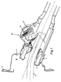
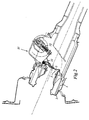
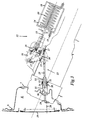
- 1 to 4 is the upper end of a filler neck 1, the lower end (not shown) of a vehicle fuel tank.
- a filler neck 1 In the upper end of the filler neck 1 an approximately pot-shaped insert 2 is inserted tightly, which reduced an opening 3 at its lower end Diameter for the passage of the filling tube 4 one Has nozzle (not shown).
- the opening 3 can be closed with the aid of a flap 5 hinged on one side, which by a spring 6 against the underside Edge of the opening is biased.
- the upper end of the filler neck 1 together with the insert 2 passes through with the interposition of a sealing collar 7 Opening in a recessed area 8 of a vehicle body 9.
- the reset area 8 is marked by a Vehicle body 9 hinged body flap 10 covered (Fig. 3).
- the panning of the cam 12 is carried out via a shaft 13 which by a Pneumatic piston 14 via a piston rod 15, one attached to it Setting 16 and a lever carried by the latter 17 is driven (Fig. 3).
- the piston 14 is in a cylinder 18 can be supplied with compressed air via a pressure line 19 and works against a compression spring 20.
- shut-off valve 21 for the filler neck 1, which via the shaft 13 from an actuator generally designated 22 is actuated, which has the elements 14 to 20. It understands however, that instead of the shut-off valve 21 and the actuator 22 shown any other type of shut-off valve or valve actuation device can be used can, as is known to the expert.
- the actuator 22 also controls the movement the body flap 10.
- the body flap 10 can with a Servo motor can be provided as a drive device, for example on electrical, hydraulic or pneumatic Driven by the actuator 22 in the manner will that when opening or closing the shutoff valve 21st at the same time the body flap 10 is opened or closed becomes.
- the drive device 23 comprises a two-part push rod 24, 25, which the sealing sleeve 7th interspersed and at one end on the body flap 10th (represented schematically by connection 26) and on the other Articulated end on the lever 17 by means of a ball joint 27 is.
- the actuator 22 is in locked their rest position.
- a recess 28 of the Lever 17 engages a pawl carried by the backdrop 16 29 a.
- the piston rod 15 is in turn on the Pawl 29 on.
- the retraction of the piston rod 15 therefore triggers first the pawl 29 from the lever 17, and only then moves the link 16 and the lever 17.
- the pawl 29 is by a spring (not shown) in that shown in Fig. 3 Locked position pretensioned and snaps when moving back the piston rod 15 again in the locking recess 28 of the lever 17 a.
- the two parts 24, 25 of the push rod 24, 25 are over a connection that triggers excessive stress 30 connected to each other.
- the connection 30 consists of a sleeve-shaped thrust guide 31 on the push rod part 24 and a slide head 32 on the push rod part 25 together.
- the sliding head 32 is with an external thread 33 and the thrust guide 31 with an inner circumferential projection engaging the thread 33 34 provided.
- the thrust guide 31 is also on several places distributed over its circumference in the axial direction slotted and surrounded by a tension spring 35. In the case of excessive The thrust guide 31 opens against the axial force Force of the tension spring 35 and the projection 34 slides on the Teeth of the thread 33.
- At the end of the slide guide 31 is one Deflection guide 36 arranged in the form of a bevel on which the sliding head 32 runs up. The deflection guide 36 steers the sliding head 32 from the thrust axis direction, whereby the Connection 30 breaks open.
- connection 30 can also a simple predetermined breaking point can be provided.
- Fig. 4 shows the generalized block diagram of the device 1-3.
- the opening and closing of the shut-off valve 21 becomes general via a mechanical connection 13 'from the actuating device 22 caused by an electrical, hydraulic, pneumatic servo motor or the like be educated can. Simultaneously with the actuation of the shut-off valve 21 the actuating device 22 controls the drive device 23 for moving the body flap 10.
- the drive device 23 a mechanical coupling member, the locking mechanism described the unidirectionality of the control path from the actuator 22 to the drive device 23 guaranteed.
- the actuating device 22 is within reach by means of a switch 41 of the driver's seat of the vehicle both in the closing and opening direction of the shut-off valve 21 and the body flap 10 controllable.
- An additional one Control path 42 for the closing direction is to the ignition circuit 43 of the vehicle connected. Pressing the Ignition key 44 of the vehicle or a similar actuating element causes via the control path 42 and the Actuating device 22 closing the shut-off valve 21 and thus also the body flap 10.
- the switch 41 exclusively for opening the locking device serves, i.e. the signal path 45 can be omitted.
Landscapes
- Engineering & Computer Science (AREA)
- Life Sciences & Earth Sciences (AREA)
- Sustainable Development (AREA)
- Sustainable Energy (AREA)
- Chemical & Material Sciences (AREA)
- Combustion & Propulsion (AREA)
- Transportation (AREA)
- Mechanical Engineering (AREA)
- Cooling, Air Intake And Gas Exhaust, And Fuel Tank Arrangements In Propulsion Units (AREA)
- Lock And Its Accessories (AREA)
- Power-Operated Mechanisms For Wings (AREA)
- Nozzles (AREA)
Claims (9)
- Dispositif de fermeture pour un tuyau de remplissage de réservoir de véhicule qui présente une soupape de fermeture (21) munie d'un dispositif d'actionnement (22) et débouche dans une zone recouvrable en retrait (8) de la carrosserie du véhicule, zone pouvant être recouverte d'un volet de carrosserie (10), le volet de carrosserie (10) présentant un dispositif d'entraínement (23) qui est commandé par le dispositif d'actionnement (22), caractérisé en ce que le dispositif d'entraínement (23) du clapet de carrosserie (10) est verrouillé dans la position de fermeture de la soupape de fermeture (21) et peut être déverrouillé par le dispositif d'actionnement (22) de la soupape de fermeture (21).
- Dispositif de fermeture selon la revendication 1, caractérisé en ce que le dispositif d'actionnement peut être commandé au moyen d'un commutateur (41) ou d'une télécommande disposée à l'intérieur du rayon de portée du siège du conducteur.
- Dispositif de fermeture selon la revendication 1 ou 2, caractérisé en ce que le dispositif d'actionnement (23) est un servomoteur qui est commandé électriquement, hydrauliquement, pneumatiquement par le dispositif d'actionnement (22).
- Dispositif de fermeture selon la revendication 1 ou 2, caractérisé en ce que le dispositif d'actionnement (23) est un réducteur qui est accouplé mécaniquement au dispositif d'actionnement (22), le dispositif d'actionnement (22) étant verrouillé dans la position de fermeture de la soupape de fermeture.
- Dispositif de fermeture selon la revendication 4, caractérisé en ce que le réducteur présente un point de rupture nominal déclenchant une liaison (30) ou analogue lors d'une sollicitation excessive.
- Dispositif de fermeture selon la revendication 5, caractérisé en ce que la liaison (30) comprend d'une part un guidage de poussée (31) et d'autre part une tête coulissante amenée dans celui-ci (32), de sorte qu'au moins l'un des éléments de guidage de poussée et la tête coulissante est munie d'une denture (33) dans laquelle l'autre élément coopère avec une saillie correspondante (34), de sorte que la denture (31) et/ou la saillie (34) sont logées de façon souple, de préférence de façon élastique.
- Dispositif de fermeture selon la revendication 6, caractérisé en ce que sur au moins une extrémité du guidage de poussée (31) vient se raccorder une tête coulissante (33) du guidage de renvoi (36) s'écartant de la direction de l'axe de poussée.
- Dispositif de fermeture selon l'une des revendications 1 à 7, caractérisé en ce que le dispositif d'actionnement pour la fermeture de la soupape de fermeture(21) peut être commandé par le circuit d'allumage (43) du véhicule de sorte que la mise en marche du circuit d'allumage (43) entraíne la fermeture de la soupape de fermeture (21) et par conséquent le volet de carrosserie (10).
- Dispositif selon la revendication 1 ou 2, caractérisé en ce que le dispositif d'actionnement (22) présente un piston pneumatique (14) ou analogue.
Applications Claiming Priority (7)
| Application Number | Priority Date | Filing Date | Title |
|---|---|---|---|
| AT189695 | 1995-11-21 | ||
| AT1896/95 | 1995-11-21 | ||
| AT189695A AT403563B (de) | 1995-11-21 | 1995-11-21 | Verschlussvorrichtung für einen fahrzeugtank-einfüllstutzen |
| AT152096A AT408637B (de) | 1996-08-26 | 1996-08-26 | Verschlussvorrichtung für einen fahrzeugtank-einfüllstutzen |
| AT152096 | 1996-08-26 | ||
| AT1520/96 | 1996-08-26 | ||
| PCT/AT1996/000233 WO1997018968A1 (fr) | 1995-11-21 | 1996-11-21 | Dispositif de fermeture du tuyau de remplissage du reservoir d'essence d'un vehicule |
Publications (2)
| Publication Number | Publication Date |
|---|---|
| EP0804349A1 EP0804349A1 (fr) | 1997-11-05 |
| EP0804349B1 true EP0804349B1 (fr) | 1999-10-13 |
Family
ID=25596075
Family Applications (1)
| Application Number | Title | Priority Date | Filing Date |
|---|---|---|---|
| EP96938845A Expired - Lifetime EP0804349B1 (fr) | 1995-11-21 | 1996-11-21 | Dispositif de fermeture du tuyau de remplissage du reservoir d'un vehicule |
Country Status (5)
| Country | Link |
|---|---|
| US (1) | US5988238A (fr) |
| EP (1) | EP0804349B1 (fr) |
| AT (1) | ATE185525T1 (fr) |
| DE (1) | DE59603348D1 (fr) |
| WO (1) | WO1997018968A1 (fr) |
Cited By (1)
| Publication number | Priority date | Publication date | Assignee | Title |
|---|---|---|---|---|
| US20220402356A1 (en) * | 2021-06-21 | 2022-12-22 | Illinois Tool Works Inc. | System for controlling vehicle |
Families Citing this family (29)
| Publication number | Priority date | Publication date | Assignee | Title |
|---|---|---|---|---|
| DE19747986C2 (de) * | 1997-10-30 | 2002-09-12 | Bosch Gmbh Robert | Verschluß für einen Tank |
| AT406850B (de) * | 1998-10-12 | 2000-09-25 | Tesma Motoren Getriebetechnik | Antriebsvorrichtung für eine verschlusseinrichtung eines fahrzeugtank-einfüllstutzens |
| KR100316929B1 (ko) * | 1999-06-11 | 2001-12-22 | 이계안 | 차량의 연료캡 자동 개폐장치 |
| US6408903B1 (en) * | 1999-11-04 | 2002-06-25 | Alfmeier Prazision Ag, Baugruppen Und Systemlosungen | Fuel tank intake assembly |
| DE10023382A1 (de) * | 2000-05-12 | 2001-11-15 | Bayerische Motoren Werke Ag | Tankklappen-Betätigungsvorrichtung |
| DE10137035A1 (de) * | 2001-07-30 | 2003-02-20 | Daimler Chrysler Ag | Tankklappenanordnung für einen Kraftwagen |
| CA2447238C (fr) * | 2002-10-29 | 2007-03-20 | Honda Motor Co.,Ltd. | Systeme de remplissage de carburant gazeux |
| DE10331073B4 (de) * | 2003-07-09 | 2007-07-12 | Alfmeier Präzision AG Baugruppen und Systemlösungen | Fahrzeugtank mit einem Einfüllrohr |
| US7096899B2 (en) * | 2003-10-04 | 2006-08-29 | Alfmeier Prazision Ag Baugruppen | Automatic tank closure for a fuel tank |
| FR2879135B1 (fr) * | 2004-12-15 | 2008-06-06 | Inergy Automotive Systems Res | Dispositif d'obturation pour tubulure de remplissage de reservoir a carburant |
| EP1852299A1 (fr) * | 2006-05-06 | 2007-11-07 | Bayerische Motoren Werke Aktiengesellschaft | Véhicule automobile doté d'un clapet de réservoir intégré et pivotant |
| FR2908087B1 (fr) * | 2006-11-08 | 2009-06-12 | Inergy Automotive Systems Res | Systeme de remplissage d'un reservoir |
| US8303337B2 (en) | 2007-06-06 | 2012-11-06 | Veedims, Llc | Hybrid cable for conveying data and power |
| US7940673B2 (en) | 2007-06-06 | 2011-05-10 | Veedims, Llc | System for integrating a plurality of modules using a power/data backbone network |
| US8151837B2 (en) * | 2007-08-27 | 2012-04-10 | Ford Global Technologies | Fuel filler closure device for automotive vehicle |
| USD638033S1 (en) | 2008-03-07 | 2011-05-17 | Ballard Claudio R | Air intake assembly |
| US8111145B2 (en) * | 2008-03-07 | 2012-02-07 | Veedims, Llc | Starter control and indicator system |
| US7856158B2 (en) * | 2008-03-07 | 2010-12-21 | Ballard Claudio R | Virtual electronic switch system |
| US20090223437A1 (en) * | 2008-03-07 | 2009-09-10 | Ballard Claudio R | Gauge having synthetic sapphire lens |
| US8089228B2 (en) * | 2008-03-07 | 2012-01-03 | Ballard Claudio R | Computer activated gas cap |
| US7806456B1 (en) | 2008-04-14 | 2010-10-05 | Kumars Zandparsa | Fuel cap smart vehicle selector lever |
| CA2724282A1 (fr) * | 2008-05-12 | 2009-11-19 | Claudio R. Ballard | Vehicule a propulsion electrique comprenant un ensemble soufflante /refroidisseur electrique sonore |
| EP2344360A1 (fr) * | 2008-09-30 | 2011-07-20 | Veedims, LLC | Systeme et procede de gestion de charge de voiture distribuee |
| US20100121551A1 (en) * | 2008-11-10 | 2010-05-13 | International Business Machines Corporation | Method, system, and program product for facilitating vehicle fueling based on vehicle state |
| USD662869S1 (en) | 2010-06-01 | 2012-07-03 | Ballard Claudio R | Automotive wheel center nut |
| US8976541B2 (en) | 2011-08-31 | 2015-03-10 | Potens Ip Holdings Llc | Electrical power and data distribution apparatus |
| EP2818351B1 (fr) * | 2013-06-26 | 2016-04-06 | Inergy Automotive Systems Research (Société Anonyme) | Procédé et système de dépressurisation d'un système de stockage de carburant de véhicule |
| US10647195B2 (en) * | 2016-01-29 | 2020-05-12 | Nissan North America, Inc. | Filling system |
| CN116409559A (zh) * | 2021-12-31 | 2023-07-11 | 中集安瑞环科技股份有限公司 | 罐式集装箱及其气动控制系统 |
Family Cites Families (14)
| Publication number | Priority date | Publication date | Assignee | Title |
|---|---|---|---|---|
| US2054145A (en) * | 1934-01-19 | 1936-09-15 | Thomas Y Tandy | Gas-tank cap lock |
| US1995960A (en) * | 1934-11-22 | 1935-03-26 | John R Boyd | Thief and fool-proof closure |
| US2035895A (en) * | 1935-03-01 | 1936-03-31 | J F Goetz | Vehicle closure and operating means therefor |
| US2151249A (en) * | 1938-12-08 | 1939-03-21 | Vidmar John Peter | Gasoline tank cap operator |
| US2294190A (en) * | 1939-05-16 | 1942-08-25 | Lee John | Automatic closure |
| US2469283A (en) * | 1947-01-30 | 1949-05-03 | Homer M Steele | Fender door lock |
| US2574836A (en) * | 1948-09-03 | 1951-11-13 | Napier & Son Ltd | Filler cap and other closures |
| US3133741A (en) * | 1960-10-10 | 1964-05-19 | Garabello Giuseppe | Fuel tank control |
| US3374007A (en) * | 1966-06-09 | 1968-03-19 | Gen Motors Corp | Tank filler arrangement |
| FR2436865A1 (fr) * | 1978-09-22 | 1980-04-18 | Renault | Dispositif de condamnation a distance de trappe a essence |
| FR2538785B2 (fr) * | 1982-07-02 | 1986-03-14 | Neiman Diffusion | Dispositif d'obturation verrouillable pour embout de reservoir |
| IT214580Z2 (it) * | 1988-05-20 | 1990-05-09 | Fiat Auto Spa | Dispositivo di introduzione del carburante comandabile dall interno di un veicolo |
| US5145081A (en) * | 1990-10-03 | 1992-09-08 | Trilby, Ltd. | Capless closure for a fuel tank filler pipe |
| DE4242228C2 (de) * | 1992-12-15 | 1995-12-07 | Webasto Karosseriesysteme | Tankverschlußsystem für einen Kraftstoffbehälter eines Kraftfahrzeuges |
-
1996
- 1996-11-21 US US08/875,169 patent/US5988238A/en not_active Expired - Lifetime
- 1996-11-21 DE DE59603348T patent/DE59603348D1/de not_active Expired - Lifetime
- 1996-11-21 WO PCT/AT1996/000233 patent/WO1997018968A1/fr not_active Ceased
- 1996-11-21 EP EP96938845A patent/EP0804349B1/fr not_active Expired - Lifetime
- 1996-11-21 AT AT96938845T patent/ATE185525T1/de active
Cited By (2)
| Publication number | Priority date | Publication date | Assignee | Title |
|---|---|---|---|---|
| US20220402356A1 (en) * | 2021-06-21 | 2022-12-22 | Illinois Tool Works Inc. | System for controlling vehicle |
| US12128756B2 (en) * | 2021-06-21 | 2024-10-29 | Illinois Tool Works Inc. | System for controlling vehicle |
Also Published As
| Publication number | Publication date |
|---|---|
| WO1997018968A1 (fr) | 1997-05-29 |
| US5988238A (en) | 1999-11-23 |
| EP0804349A1 (fr) | 1997-11-05 |
| ATE185525T1 (de) | 1999-10-15 |
| DE59603348D1 (de) | 1999-11-18 |
Similar Documents
| Publication | Publication Date | Title |
|---|---|---|
| EP0804349B1 (fr) | Dispositif de fermeture du tuyau de remplissage du reservoir d'un vehicule | |
| DE3519203C2 (fr) | ||
| EP1759131B1 (fr) | Dispositif actionneur permettant de commander un mecanisme de verrouillage | |
| AT403141B (de) | Verschlussvorrichtung für einen fahrzeugtank-einfüllstutzen | |
| DE3117935C2 (fr) | ||
| EP0296618B1 (fr) | Réservoir d'essence autoserrant | |
| EP4448899A1 (fr) | Serrure de véhicule à moteur, en particulier serrure de portière de véhicule à moteur | |
| EP1801332A2 (fr) | Serrure pour véhicule automobile | |
| DE4005641C2 (fr) | ||
| DE19547724A1 (de) | Schloß, insbesondere für Kraftfahrzeugtüren | |
| WO2012022440A1 (fr) | Ensemble entraînement | |
| DE102017115191A1 (de) | Ventil, insbesondere Servoventil | |
| EP4112851B1 (fr) | Serrure de véhicule automobile, en particulier serrure de portière de véhicule automobile | |
| DE19946484B4 (de) | Antriebsvorrichtung für eine Verschlusseinrichtung eines Fahrzeugtank-Einfüllstutzens | |
| DE3018920C2 (de) | Verriegelung für Kolben von Druckmittelzylindern | |
| DE102020213052A1 (de) | Entriegelungssystem für eine Fahrzeugtür | |
| DE4215639C2 (de) | Vorrichtung zur Arretierung einer Auswurfklappe für den Preßkasten einer Ballenpresse | |
| AT403563B (de) | Verschlussvorrichtung für einen fahrzeugtank-einfüllstutzen | |
| DE10010809A1 (de) | Kraftfahrzeug-Türschloß | |
| DE4130094C1 (en) | Door lock for car - has auxiliary lever connected to safety lever by toggle spring mechanism | |
| EP1527930A2 (fr) | Dispositif de verrouillage et/ou déverrouillage d'un volet d'obturation d'un réservoir | |
| EP1772577A2 (fr) | Serrure pour véhicule automobile | |
| DE19528974A1 (de) | Wegeventil | |
| EP0735224B1 (fr) | Dispositif de commande pour une fenêtre latérale de véhicule | |
| DE10164484A1 (de) | Kraftfahrzeugtürverschluss |
Legal Events
| Date | Code | Title | Description |
|---|---|---|---|
| PUAI | Public reference made under article 153(3) epc to a published international application that has entered the european phase |
Free format text: ORIGINAL CODE: 0009012 |
|
| 17P | Request for examination filed |
Effective date: 19970708 |
|
| AK | Designated contracting states |
Kind code of ref document: A1 Designated state(s): AT DE FR GB IT |
|
| GRAG | Despatch of communication of intention to grant |
Free format text: ORIGINAL CODE: EPIDOS AGRA |
|
| GRAG | Despatch of communication of intention to grant |
Free format text: ORIGINAL CODE: EPIDOS AGRA |
|
| GRAH | Despatch of communication of intention to grant a patent |
Free format text: ORIGINAL CODE: EPIDOS IGRA |
|
| 17Q | First examination report despatched |
Effective date: 19990310 |
|
| GRAH | Despatch of communication of intention to grant a patent |
Free format text: ORIGINAL CODE: EPIDOS IGRA |
|
| GRAA | (expected) grant |
Free format text: ORIGINAL CODE: 0009210 |
|
| AK | Designated contracting states |
Kind code of ref document: B1 Designated state(s): AT DE FR GB IT |
|
| REF | Corresponds to: |
Ref document number: 185525 Country of ref document: AT Date of ref document: 19991015 Kind code of ref document: T |
|
| GBT | Gb: translation of ep patent filed (gb section 77(6)(a)/1977) |
Effective date: 19991014 |
|
| REF | Corresponds to: |
Ref document number: 59603348 Country of ref document: DE Date of ref document: 19991118 |
|
| ET | Fr: translation filed | ||
| PLBE | No opposition filed within time limit |
Free format text: ORIGINAL CODE: 0009261 |
|
| STAA | Information on the status of an ep patent application or granted ep patent |
Free format text: STATUS: NO OPPOSITION FILED WITHIN TIME LIMIT |
|
| 26N | No opposition filed | ||
| REG | Reference to a national code |
Ref country code: GB Ref legal event code: IF02 |
|
| PGFP | Annual fee paid to national office [announced via postgrant information from national office to epo] |
Ref country code: FR Payment date: 20061124 Year of fee payment: 11 |
|
| PGFP | Annual fee paid to national office [announced via postgrant information from national office to epo] |
Ref country code: GB Payment date: 20061127 Year of fee payment: 11 |
|
| PGFP | Annual fee paid to national office [announced via postgrant information from national office to epo] |
Ref country code: IT Payment date: 20061130 Year of fee payment: 11 |
|
| GBPC | Gb: european patent ceased through non-payment of renewal fee |
Effective date: 20071121 |
|
| REG | Reference to a national code |
Ref country code: FR Ref legal event code: ST Effective date: 20080930 |
|
| PG25 | Lapsed in a contracting state [announced via postgrant information from national office to epo] |
Ref country code: GB Free format text: LAPSE BECAUSE OF NON-PAYMENT OF DUE FEES Effective date: 20071121 |
|
| PG25 | Lapsed in a contracting state [announced via postgrant information from national office to epo] |
Ref country code: FR Free format text: LAPSE BECAUSE OF NON-PAYMENT OF DUE FEES Effective date: 20071130 |
|
| PG25 | Lapsed in a contracting state [announced via postgrant information from national office to epo] |
Ref country code: IT Free format text: LAPSE BECAUSE OF NON-PAYMENT OF DUE FEES Effective date: 20071121 |
|
| PGFP | Annual fee paid to national office [announced via postgrant information from national office to epo] |
Ref country code: AT Payment date: 20131113 Year of fee payment: 18 Ref country code: DE Payment date: 20131121 Year of fee payment: 18 |
|
| REG | Reference to a national code |
Ref country code: DE Ref legal event code: R119 Ref document number: 59603348 Country of ref document: DE |
|
| REG | Reference to a national code |
Ref country code: AT Ref legal event code: MM01 Ref document number: 185525 Country of ref document: AT Kind code of ref document: T Effective date: 20141121 |
|
| PG25 | Lapsed in a contracting state [announced via postgrant information from national office to epo] |
Ref country code: AT Free format text: LAPSE BECAUSE OF NON-PAYMENT OF DUE FEES Effective date: 20141121 |
|
| PG25 | Lapsed in a contracting state [announced via postgrant information from national office to epo] |
Ref country code: DE Free format text: LAPSE BECAUSE OF NON-PAYMENT OF DUE FEES Effective date: 20150602 |