EP0804676B1 - Tourniquet - Google Patents
Tourniquet Download PDFInfo
- Publication number
- EP0804676B1 EP0804676B1 EP96937120A EP96937120A EP0804676B1 EP 0804676 B1 EP0804676 B1 EP 0804676B1 EP 96937120 A EP96937120 A EP 96937120A EP 96937120 A EP96937120 A EP 96937120A EP 0804676 B1 EP0804676 B1 EP 0804676B1
- Authority
- EP
- European Patent Office
- Prior art keywords
- blocking
- passage
- user
- turnstile
- sensor
- Prior art date
- Legal status (The legal status is an assumption and is not a legal conclusion. Google has not performed a legal analysis and makes no representation as to the accuracy of the status listed.)
- Expired - Lifetime
Links
- 230000000903 blocking effect Effects 0.000 claims abstract description 35
- 230000004888 barrier function Effects 0.000 claims abstract description 8
- 230000005693 optoelectronics Effects 0.000 claims abstract description 6
- 238000001514 detection method Methods 0.000 claims description 10
- 238000013475 authorization Methods 0.000 abstract description 6
- 238000000034 method Methods 0.000 abstract description 2
- 238000012795 verification Methods 0.000 abstract 1
- 230000002401 inhibitory effect Effects 0.000 description 2
- 241000237858 Gastropoda Species 0.000 description 1
- 230000008054 signal transmission Effects 0.000 description 1
- 230000001629 suppression Effects 0.000 description 1
Images

Classifications
-
- E—FIXED CONSTRUCTIONS
- E06—DOORS, WINDOWS, SHUTTERS, OR ROLLER BLINDS IN GENERAL; LADDERS
- E06B—FIXED OR MOVABLE CLOSURES FOR OPENINGS IN BUILDINGS, VEHICLES, FENCES OR LIKE ENCLOSURES IN GENERAL, e.g. DOORS, WINDOWS, BLINDS, GATES
- E06B11/00—Means for allowing passage through fences, barriers or the like, e.g. stiles
- E06B11/08—Turnstiles; Gates for control of entry or exit of persons, e.g. in supermarkets
-
- G—PHYSICS
- G07—CHECKING-DEVICES
- G07C—TIME OR ATTENDANCE REGISTERS; REGISTERING OR INDICATING THE WORKING OF MACHINES; GENERATING RANDOM NUMBERS; VOTING OR LOTTERY APPARATUS; ARRANGEMENTS, SYSTEMS OR APPARATUS FOR CHECKING NOT PROVIDED FOR ELSEWHERE
- G07C9/00—Individual registration on entry or exit
- G07C9/10—Movable barriers with registering means
- G07C9/15—Movable barriers with registering means with arrangements to prevent the passage of more than one individual at a time
Definitions
- the invention relates to a turnstile for a passage, with one of a drive rotatable locking element that in the locked position the passage has blocking blocking arm, and with a sensor downstream of the blocking position, the locking element, in particular after checking the access authorization of a user releases the passage to the sensor by a first part of a rotation, and then in Dependence on the advancement of the user determined by the sensor over a second part of the rotation in the same direction to the next locked position.
- Such a turnstile can be found, for example, in WO-A 94/25720.
- the drive motor starts to move set and the locking arm at a small angle of about 10 ° in a stop position moved, in which an optoelectronic sensor is released. If the User has indicated his willingness to go through that he is in has moved up the detection range of the sensor, the sensor will Drive motor started again and the locking element rotated until the next locking arm is in the locked position.
- Usual turnstiles have four or three locking arms three-arm turnstile has an approximately 45 ° inclined drive shaft. In the The direction available is therefore small or short for the user. because the turnstile functionally functions as a moving lock chamber with a front one and rear boundary forms, and the passage of the turnstile can especially then be difficult if the user objects, for example Sporting goods, bags, etc. It happens again and again that the User himself, especially jamming the objects between the locking arms.
- the object of the invention is to remedy these disadvantages and Increased passage comfort, especially when transporting objects.
- the locking element only one has single locking arm and between the locking positions by 360 ° twisted.
- the task can also be solved in a second embodiment be that the locking element has two locking arms offset by 180 ° and itself rotated by 180 ° between the locking positions.
- an optoelectronic sensor is used as the sensor other presence or passage detectors are also provided usable.
- the sensor is preferably installed above the drive shaft in the housing, so that the Signal transmission to the engine control in the usual way via fixed lines can.
- the optoelectronic sensor can detect at least one of changes in reflection emitted light beam include appealing light scanner, which with a External light and background suppression is equipped.
- the sent out The detection beam is reflected by the passing user.
- the reflected light hits to a first light receiver that matches the received light portion with that Light component compares that to a second light receiver from that at a greater distance lying background is reflected. Because the positions of both light receivers are adjustable, this enables the range of the detection beam to be limited by determining the distance of its intersection with the reflection beam of the second light receiver. This difference method is largely independent of the reflective properties. It is preferably provided that the light sensor Emits infrared light.
- a DC motor which is used in the Stop position can be short-circuited. Also preferred is on the drive shaft arranged a worm wheel in which a non-inhibiting worm engages, a magnetic brake and a direction of rotation detection device on its shaft is provided, and which is driven by the motor via a traction means.
- the magnetic brake can be activated especially in the locked position.
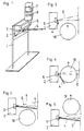
- FIG. 1 shows an oblique view of a first embodiment of the turnstile
- Fig. 2 is a schematic plan view of the locked position
- Fig.3 is a schematic Top view of the open position
- Fig. 4 is a schematic plan view of a trigger position of the user
- Fig. 5 is a schematic plan view of the next Locked position
- Fig. 6 is an oblique view of a second embodiment of the Turnstile
- FIGS. 7 to 10 each show schematic plan views according to FIGS. 2 to 5 to the second embodiment.
- the height of a housing 2 of a turnstile is arranged on a frame 1.
- the turnstile is assigned to a through lane and has a locking element 3 with a locking arm 4, which is in a locking position at an angle lies between 0 ° and about 10 ° in front of an imaginary middle stop line.
- a worm wheel is attached, in which a non-inhibiting Snail engages by an electric drive motor via a traction mechanism is driven.
- the blocking element 3 is in the blocking position of the blocking arm 4 held by an electromagnetic brake attached to the shaft of the worm attacks.
- the turnstile is also with one provided optoelectronic sensor 5, via which the drive motor is switched, and preferably a control device 7 is also provided, which is a transceiver unit 8 for a contactless control, if necessary also one Magnetic card reader and a display.
- the locked position of the turnstile shows Fig. 2 to Fig. 5.
- the locking element 3 rotates by 180 ° to 210 °, so that access to the Detection area 6 possible and the passage barrier is completely free (Fig. 3). Does that go User 18 further forward, he enters, as can be seen from Fig. 4, in the Detection area 6, and the sensor 5 is in turn the motor Turnstile activated. This rotates the locking element 3 in the same direction continue until the locking arm 4 returns to the locking position in which the brake is reactivated. An exact position of the locking arm is neither in the Lock position still required in the intermediate position. It is convenient if the second Partial rotation from the intermediate position into the blocking position relatively quickly can take place so that a subsequent user cannot pass unauthorized. The second partial rotation should therefore not exceed 90 °.
- the blocking element 3 has two Lock arms 4 offset by 180 °.
- a first partial rotation of 90 ° leads to here too an open passage, as can be seen from FIGS. 8 and 9.
- the turnstile according to the invention is of the length of the user or with the User moving objects independently. It is therefore also conceivable that the turnstile on lanes for motor vehicles, for example when entering Parking garages are used, the words "passage” and “access authorization” are to be understood as “passage” or "access authorization”.
Landscapes
- Physics & Mathematics (AREA)
- General Physics & Mathematics (AREA)
- Engineering & Computer Science (AREA)
- Civil Engineering (AREA)
- Structural Engineering (AREA)
- Lock And Its Accessories (AREA)
- Refuge Islands, Traffic Blockers, Or Guard Fence (AREA)
- Switches With Compound Operations (AREA)
- Rotary Switch, Piano Key Switch, And Lever Switch (AREA)
- Non-Deflectable Wheels, Steering Of Trailers, Or Other Steering (AREA)
- Operating, Guiding And Securing Of Roll- Type Closing Members (AREA)
- Valve-Gear Or Valve Arrangements (AREA)
- Conveying Record Carriers (AREA)
- Devices For Checking Fares Or Tickets At Control Points (AREA)
Claims (5)
- Tourniquet de passage comportant un élément de blocage (3) qui peut être entraíné en rotation par un mécanisme d'entraínement et qui est pourvu d'un bras de blocage (4) bloquant le passage dans la position de blocage, et comportant un capteur (5) monté en aval de la position de blocage dans le sens de passage, l'élément de blocage (3), en particulier après contrôle de l'autorisation d'accès d'un usager (18), libérant le passage vers le capteur (5) par une première partie d'une rotation puis, en fonction de l'avancement de l'usager (18) détecté par le capteur (5), poursuivant sa rotation dans le même sens sur une seconde partie pour arriver dans la position de blocage suivante, caractérisé en ce que l'élément de blocage (3) comporte un seul bras de blocage (4) et tourne chaque fois de 360° entre les positions de blocage.
- Tourniquet de passage comportant un élément de blocage (3) qui peut être entraíné en rotation par un mécanisme d'entraínement et qui est pourvu d'un bras de blocage (4) bloquant le passage dans la position de blocage, et comportant un capteur (5) monté en aval de la position de blocage dans le sens de passage, l'élément de blocage (3), en particulier après contrôle de l'autorisation d'accès d'un usager (18) libérant le passage vers le capteur (5) par une première partie d'une rotation puis, en fonction de l'avancement de l'usager (18) détecté par le capteur (5), poursuivant sa rotation dans le même sens sur une seconde partie pour arriver dans la position de blocage suivante, caractérisé en ce que l'élément de blocage (3) comporte deux bras de blocage (4) décalés de 180° et tourne chaque fois de 180° entre les positions de blocage.
- Tourniquet selon la revendication 1 ou 2, caractérisé en ce que la première partie de la rotation de l'élément de blocage (3) couvre un angle d'au moins 90°.
- Tourniquet selon la revendication 1 ou 2, caractérisé en ce que la seconde partie de la rotation de l'élément de blocage (3) couvre un angle d'au plus 90°.
- Tourniquet selon l'une des revendications 1 à 4, caractérisé en ce que le capteur (5) est un capteur opto électronique.
Applications Claiming Priority (4)
| Application Number | Priority Date | Filing Date | Title |
|---|---|---|---|
| AT187495 | 1995-11-16 | ||
| AT0187495A AT405338B (de) | 1995-11-16 | 1995-11-16 | Drehsperre |
| AT1874/95 | 1995-11-16 | ||
| PCT/AT1996/000221 WO1997018379A1 (fr) | 1995-11-16 | 1996-11-14 | Tourniquet |
Publications (2)
| Publication Number | Publication Date |
|---|---|
| EP0804676A1 EP0804676A1 (fr) | 1997-11-05 |
| EP0804676B1 true EP0804676B1 (fr) | 2002-04-03 |
Family
ID=3522886
Family Applications (1)
| Application Number | Title | Priority Date | Filing Date |
|---|---|---|---|
| EP96937120A Expired - Lifetime EP0804676B1 (fr) | 1995-11-16 | 1996-11-14 | Tourniquet |
Country Status (5)
| Country | Link |
|---|---|
| US (2) | US6012252A (fr) |
| EP (1) | EP0804676B1 (fr) |
| AT (2) | AT405338B (fr) |
| DE (1) | DE59609012D1 (fr) |
| WO (1) | WO1997018379A1 (fr) |
Cited By (2)
| Publication number | Priority date | Publication date | Assignee | Title |
|---|---|---|---|---|
| EP1609942A1 (fr) | 2004-06-21 | 2005-12-28 | SkiData AG | Tourniquet |
| US7845115B2 (en) | 2006-08-31 | 2010-12-07 | Skidata Ag | Access control apparatus |
Families Citing this family (17)
| Publication number | Priority date | Publication date | Assignee | Title |
|---|---|---|---|---|
| US6617960B1 (en) | 1998-02-18 | 2003-09-09 | Teamaxess Ticketing Gmbh | Arrangement for controlling access of persons, and access terminal |
| AT407096B (de) * | 1998-05-25 | 2000-12-27 | Karl Gotschlich Maschinenbau G | Drehsperre |
| USD438312S1 (en) | 1998-09-07 | 2001-02-27 | Systems Ag | Locking device |
| GB2342989A (en) * | 1998-10-23 | 2000-04-26 | Integrated Design Limited | Detection system |
| DE10046335A1 (de) * | 2000-09-19 | 2002-04-18 | Skidata Ag | Zugangskontrolleinrichtung |
| AT6665U1 (de) * | 2002-10-09 | 2004-01-26 | Karl Gotschlich Maschb Ges M B | Drehsperre |
| DE102004013965B3 (de) * | 2004-03-19 | 2005-12-01 | Skidata Ag | Zutrittskontrollvorrichtung |
| US7762025B2 (en) | 2004-11-19 | 2010-07-27 | Modular Security Systems, Inc. | Containerized access control system |
| US7762022B2 (en) * | 2005-07-08 | 2010-07-27 | Bea, Inc. | Automatic door opening and closing system and method of control thereof |
| DE102006026221A1 (de) * | 2006-06-06 | 2007-12-13 | Skidata Ag | Drehsperre |
| EP1892676A1 (fr) * | 2006-08-08 | 2008-02-27 | SkiData AG | Système de contrôle d'accès |
| US7823338B2 (en) * | 2007-04-10 | 2010-11-02 | Modular Security Systems, Inc. | Modular access control system |
| AT10305U1 (de) | 2007-05-10 | 2008-12-15 | Axess Ag | Einrichtung zur berührungslosen kontrolle von personen |
| US8827155B2 (en) | 2011-11-10 | 2014-09-09 | Axess Ag | Access control gate |
| US10448792B2 (en) * | 2012-10-24 | 2019-10-22 | Dean Cawthon | Hand hygiene |
| EP3239451B1 (fr) * | 2016-04-26 | 2018-03-14 | Skidata Ag | Dispositif de controle d'acces pour personnes sous forme de verrou rotatif ou dispositif de comptage de personnes |
| DE102022100279A1 (de) | 2022-01-07 | 2023-07-13 | ELKA Torantriebe GmbH u. Co. Betriebs KG | Vorrichtung zum Vereinzeln von Personen in einem Vereinzelungsbereich sowie Personenvereinzelungseinrichtung |
Family Cites Families (10)
| Publication number | Priority date | Publication date | Assignee | Title |
|---|---|---|---|---|
| DE1474706C3 (de) * | 1965-04-02 | 1974-01-10 | Acker Norbert Karl | Automationseinrichtung für Kassenstellen von Verkaufsanlagen |
| US3998008A (en) * | 1975-04-30 | 1976-12-21 | Qonaar Corporation | Turnstile head mechanism construction |
| DE3517720A1 (de) * | 1985-05-17 | 1986-11-20 | Rudolf Wanzl Kg, 8874 Leipheim | Schwenktueranordnung fuer personendurchgangsanlagen |
| NL8902681A (nl) * | 1989-10-31 | 1991-05-16 | Jacob Robert Alfred Huber En E | Draaideur. |
| NL9100527A (nl) * | 1991-03-26 | 1992-10-16 | Boon Edam Bv | Draaideur voor het beveiligen van de toegang en/of het verlaten van een ruimte. |
| IT1254849B (it) * | 1992-03-25 | 1995-10-11 | Italdis Ind Spa | Tornello antisimulazione |
| IT1255955B (it) * | 1992-11-26 | 1995-11-17 | Bussola di sicurezza per banche e simili | |
| EP0622518A3 (fr) * | 1993-04-26 | 1995-05-24 | Beeler Werner Autec | Mécanisme de rotation. |
| US5704163A (en) * | 1993-05-03 | 1998-01-06 | Skidata Computer Gesellschaft M.B.H. | Turnstile |
| US5705982A (en) * | 1996-08-01 | 1998-01-06 | North America Technitron Corporation | Intrusion detection, register and indication apparatus |
-
1995
- 1995-11-16 AT AT0187495A patent/AT405338B/de not_active IP Right Cessation
-
1996
- 1996-11-14 EP EP96937120A patent/EP0804676B1/fr not_active Expired - Lifetime
- 1996-11-14 WO PCT/AT1996/000221 patent/WO1997018379A1/fr not_active Ceased
- 1996-11-14 US US08/875,149 patent/US6012252A/en not_active Expired - Lifetime
- 1996-11-14 DE DE59609012T patent/DE59609012D1/de not_active Expired - Lifetime
- 1996-11-14 AT AT96937120T patent/ATE215663T1/de active
-
1999
- 1999-06-15 US US09/333,807 patent/US6170194B1/en not_active Expired - Lifetime
Cited By (3)
| Publication number | Priority date | Publication date | Assignee | Title |
|---|---|---|---|---|
| EP1609942A1 (fr) | 2004-06-21 | 2005-12-28 | SkiData AG | Tourniquet |
| US7392617B2 (en) | 2004-06-21 | 2008-07-01 | Skidata Ag | Rotating barrier |
| US7845115B2 (en) | 2006-08-31 | 2010-12-07 | Skidata Ag | Access control apparatus |
Also Published As
| Publication number | Publication date |
|---|---|
| DE59609012D1 (de) | 2002-05-08 |
| ATE215663T1 (de) | 2002-04-15 |
| EP0804676A1 (fr) | 1997-11-05 |
| US6170194B1 (en) | 2001-01-09 |
| WO1997018379A1 (fr) | 1997-05-22 |
| US6012252A (en) | 2000-01-11 |
| AT405338B (de) | 1999-07-26 |
| ATA187495A (de) | 1998-11-15 |
Similar Documents
| Publication | Publication Date | Title |
|---|---|---|
| EP0804676B1 (fr) | Tourniquet | |
| DE69303581T2 (de) | Sicherheitsdrehtür für Banken und dergleichen | |
| DE69400962T2 (de) | Vorrichtung zum Prüfen der Gleichförmigkeit und zum Übertragen von in eine Ausgabevorrichtung eingeführte Gegenstände | |
| DE69332230T2 (de) | Hochsicherheits-Verriegelungsmechanismus | |
| EP0431363B1 (fr) | Sas de sécurité pour personnes | |
| EP1577842B1 (fr) | Dispositif de contrôle d'accès | |
| EP0273965A1 (fr) | Installation pour determiner le nombre de personnes et leur direction de deplacement dans un local surveille ou un sas. | |
| DE4137010A1 (de) | Als raumueberwachungsvorrichtung ausgebildeter waren-, dienstleistungs- oder gluecksspielautomat | |
| DE1929922B2 (de) | Selbsttätige Passierscheinkontrollsperre | |
| DE3319530C2 (de) | Vorrichtung zur Aufnahme von Fahrzeugen, wie mit Rollen versehene Wagen | |
| EP0697056B1 (fr) | Tourniquet | |
| EP1609942B1 (fr) | Tourniquet | |
| DE69321638T2 (de) | Simulation des Durchganges verhinderndes Drehkreuz | |
| WO2008058521A2 (fr) | Porte tambour | |
| DE69107985T2 (de) | Drehtür, insbesondere zur Sicherung einer Raumzugang. | |
| EP3736783B1 (fr) | Distributeur automatique de billets | |
| DE19519221A1 (de) | Annahmevorrichtung für Stückgüter | |
| DE10216760A1 (de) | Fahrzeugerfassungsvorrichtung | |
| DE29701462U1 (de) | Vorrichtung zur automatischen Steuerung von Toren oder Türen | |
| EP1416116B1 (fr) | Tourniquet | |
| DE69407002T2 (de) | Apparat zum Kontrollieren des Durchquerens eines genehmigungspflichtigen Durchganges | |
| DE102008010848A1 (de) | Einwurfvorrichtung für Münzen | |
| EP0446207A1 (fr) | Procede de guidage de flux de visiteurs | |
| DE202009010858U1 (de) | Durchgangs- oder Durchfahrtssperranlage mit einer Vorrichtung zur Überwachung des Durchgangs- oder Durchfahrtsbereichs | |
| DE20009698U1 (de) | Fahrradparkhausterminal-Kombinierte Personen und Fahrradschleuse |
Legal Events
| Date | Code | Title | Description |
|---|---|---|---|
| PUAI | Public reference made under article 153(3) epc to a published international application that has entered the european phase |
Free format text: ORIGINAL CODE: 0009012 |
|
| 17P | Request for examination filed |
Effective date: 19970704 |
|
| AK | Designated contracting states |
Kind code of ref document: A1 Designated state(s): AT CH DE FR LI SE |
|
| 17Q | First examination report despatched |
Effective date: 20010402 |
|
| GRAG | Despatch of communication of intention to grant |
Free format text: ORIGINAL CODE: EPIDOS AGRA |
|
| GRAG | Despatch of communication of intention to grant |
Free format text: ORIGINAL CODE: EPIDOS AGRA |
|
| GRAG | Despatch of communication of intention to grant |
Free format text: ORIGINAL CODE: EPIDOS AGRA |
|
| GRAH | Despatch of communication of intention to grant a patent |
Free format text: ORIGINAL CODE: EPIDOS IGRA |
|
| RAP1 | Party data changed (applicant data changed or rights of an application transferred) |
Owner name: SKIDATA AG |
|
| GRAH | Despatch of communication of intention to grant a patent |
Free format text: ORIGINAL CODE: EPIDOS IGRA |
|
| GRAA | (expected) grant |
Free format text: ORIGINAL CODE: 0009210 |
|
| AK | Designated contracting states |
Kind code of ref document: B1 Designated state(s): AT CH DE FR LI SE |
|
| REF | Corresponds to: |
Ref document number: 215663 Country of ref document: AT Date of ref document: 20020415 Kind code of ref document: T |
|
| REG | Reference to a national code |
Ref country code: CH Ref legal event code: EP |
|
| REF | Corresponds to: |
Ref document number: 59609012 Country of ref document: DE Date of ref document: 20020508 |
|
| REG | Reference to a national code |
Ref country code: CH Ref legal event code: NV Representative=s name: ISLER & PEDRAZZINI AG |
|
| ET | Fr: translation filed | ||
| PLBE | No opposition filed within time limit |
Free format text: ORIGINAL CODE: 0009261 |
|
| STAA | Information on the status of an ep patent application or granted ep patent |
Free format text: STATUS: NO OPPOSITION FILED WITHIN TIME LIMIT |
|
| 26N | No opposition filed |
Effective date: 20030106 |
|
| REG | Reference to a national code |
Ref country code: CH Ref legal event code: PCAR Free format text: ISLER & PEDRAZZINI AG;POSTFACH 1772;8027 ZUERICH (CH) |
|
| REG | Reference to a national code |
Ref country code: FR Ref legal event code: PLFP Year of fee payment: 20 |
|
| PGFP | Annual fee paid to national office [announced via postgrant information from national office to epo] |
Ref country code: CH Payment date: 20151118 Year of fee payment: 20 Ref country code: DE Payment date: 20151119 Year of fee payment: 20 |
|
| PGFP | Annual fee paid to national office [announced via postgrant information from national office to epo] |
Ref country code: AT Payment date: 20151119 Year of fee payment: 20 Ref country code: SE Payment date: 20151118 Year of fee payment: 20 Ref country code: FR Payment date: 20151119 Year of fee payment: 20 |
|
| REG | Reference to a national code |
Ref country code: DE Ref legal event code: R071 Ref document number: 59609012 Country of ref document: DE |
|
| REG | Reference to a national code |
Ref country code: CH Ref legal event code: PL |
|
| REG | Reference to a national code |
Ref country code: AT Ref legal event code: MK07 Ref document number: 215663 Country of ref document: AT Kind code of ref document: T Effective date: 20161114 |