EP0804889A2 - Gas spring for a chair - Google Patents
Gas spring for a chair Download PDFInfo
- Publication number
- EP0804889A2 EP0804889A2 EP97106443A EP97106443A EP0804889A2 EP 0804889 A2 EP0804889 A2 EP 0804889A2 EP 97106443 A EP97106443 A EP 97106443A EP 97106443 A EP97106443 A EP 97106443A EP 0804889 A2 EP0804889 A2 EP 0804889A2
- Authority
- EP
- European Patent Office
- Prior art keywords
- housing
- piston
- gas spring
- piston rod
- valve
- Prior art date
- Legal status (The legal status is an assumption and is not a legal conclusion. Google has not performed a legal analysis and makes no representation as to the accuracy of the status listed.)
- Granted
Links
Images

Classifications
-
- A—HUMAN NECESSITIES
- A47—FURNITURE; DOMESTIC ARTICLES OR APPLIANCES; COFFEE MILLS; SPICE MILLS; SUCTION CLEANERS IN GENERAL
- A47C—CHAIRS; SOFAS; BEDS
- A47C3/00—Chairs characterised by structural features; Chairs or stools with rotatable or vertically-adjustable seats
- A47C3/20—Chairs or stools with vertically-adjustable seats
- A47C3/30—Chairs or stools with vertically-adjustable seats with vertically-acting fluid cylinder
-
- F—MECHANICAL ENGINEERING; LIGHTING; HEATING; WEAPONS; BLASTING
- F16—ENGINEERING ELEMENTS AND UNITS; GENERAL MEASURES FOR PRODUCING AND MAINTAINING EFFECTIVE FUNCTIONING OF MACHINES OR INSTALLATIONS; THERMAL INSULATION IN GENERAL
- F16F—SPRINGS; SHOCK-ABSORBERS; MEANS FOR DAMPING VIBRATION
- F16F9/00—Springs, vibration-dampers, shock-absorbers, or similarly-constructed movement-dampers using a fluid or the equivalent as damping medium
- F16F9/32—Details
-
- F—MECHANICAL ENGINEERING; LIGHTING; HEATING; WEAPONS; BLASTING
- F16—ENGINEERING ELEMENTS AND UNITS; GENERAL MEASURES FOR PRODUCING AND MAINTAINING EFFECTIVE FUNCTIONING OF MACHINES OR INSTALLATIONS; THERMAL INSULATION IN GENERAL
- F16F—SPRINGS; SHOCK-ABSORBERS; MEANS FOR DAMPING VIBRATION
- F16F9/00—Springs, vibration-dampers, shock-absorbers, or similarly-constructed movement-dampers using a fluid or the equivalent as damping medium
- F16F9/02—Springs, vibration-dampers, shock-absorbers, or similarly-constructed movement-dampers using a fluid or the equivalent as damping medium using gas only or vacuum
- F16F9/0209—Telescopic
- F16F9/0245—Means for adjusting the length of, or for locking, the spring or dampers
Definitions
- the invention relates to a chair gas spring according to the preamble of claim 1.
- the invention is therefore based on the object of designing a chair gas spring of the generic type in such a way that it has a maximum possible height adjustment range in the loaded state.
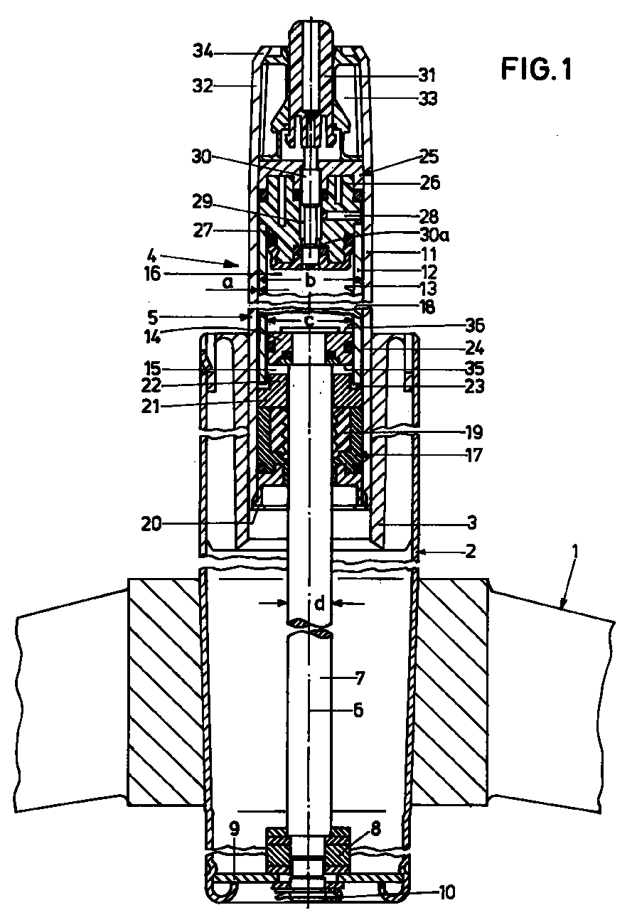
- the chair column shown in FIG. 1 has a guide tube 2 attached to a base 1, which is provided with a guide bush 3 at its upper open end.
- a gas spring 4 which is adjustable in terms of eyes and the housing 5 of which is arranged so as to be displaceable in the guide bush 3 in the direction of a common central longitudinal axis 6.
- a piston rod 7 is led out of the housing 5 downwards, the free end of which is supported by means of an axial bearing 8 on a base 9 of the guide tube 2 and is fastened thereon by means of a fastening element 10.
- the housing 5 of the gas spring 4 has an outer cylinder 11 and an inner cylinder 12 arranged concentrically therein.
- a piston 14 lies in a sealed manner on the inner wall 13 of the inner cylinder 12, which is attached to the inner end of the piston rod 7.
- the piston 14 divides the inner cylinder 12 into two housing spaces 15, 16.
- the piston rod 7 is guided in the region of its exit from the housing 5 in a guide 17 which is sealed off from the inner wall 18 of the outer cylinder 11 and in which a multiple lip seal 19 is arranged which bears against the piston rod 7.
- the guide 17 is held by means of a flange 20 of the outer cylinder 11. Due to the design described, the gas spring 4 is sealed gas and liquid-tight at the outlet of the piston rod 7.
- a centering ring 21, which bears against the guide 17 and covers the seal 19, is arranged towards the adjacent housing space 15, which, on the one hand, bears against the inner wall 18 of the outer cylinder 11 and is thereby centered on the axis 6 and, on the other hand, one which receives the inner cylinder 12 and the axis 6 centering centering collar 22.
- the inner cylinder 12 is supported on the centering ring 21 in the direction of the axis 6.
- connecting channels 23 are formed which connect the housing space 15 formed between the piston 14 and the piston rod outlet end of the housing 5 to a gap-like annular overflow channel 24 formed between the outer cylinder 11 and the inner cylinder 12.
- a valve 25 is arranged in the housing 5, the valve housing 26 of which rests sealed against the inner wall 18 of the outer cylinder 11 and the inner wall 13 of the inner cylinder 12 and which centers the inner cylinder 12 to the axis 6 by means of a centering collar 27 and which Inner cylinder 12 is supported in the direction of the axis 6.
- the valve housing 26 has a connecting channel 28 connected to the overflow channel 24, which is connected to a connecting space 29 formed concentrically to the axis 6 in the valve housing 26 and which can be connected to the housing space 16 between the valve 25 and the piston 14.
- a valve pin 30 which opens a closing point 30a when pushed in in the direction of the housing space 16 and thus connects the connection space 29 to the housing space 16 and that in it In the rest position shown in the drawing, the closing point 30a closes and thus separates the connecting space from the building space 16.
- the valve pin 30 is led outwards from the valve housing 26 and bears against a slide 31 which is guided and held in a fastening section 32 of the housing 5 in the direction of the axis 6.
- a spacer 33 is arranged in the fastening section 32, which is held by a flange 34 of the outer cylinder 11. This spacer 33 also holds the valve 25 in its axial position.
- the seat support of a chair or armchair can be fastened to this fastening section 32.
- the slider 31 is operated by means of a lever or the like.
- the housing spaces 15, 16 and the connecting channels 23, 28, the connecting space 29 and the overflow channel 24 are filled with compressed gas and possibly some oil.
- the piston rod 7 can spring with the piston 14 relative to the housing 5. If the closing point 30a of the valve 25 is opened by pushing the valve pin 30 in the direction of the housing space 16, then either gas from the housing space 15 through the connecting channels 23, the overflow channel 24, the connecting channel 28 and the connecting space 29 into the housing space 16 or vice versa flow depending on the force acting on the piston rod 7 in the direction of the axis 6.
- the structure of the entire chair column including the gas spring 5 and its mode of operation as a chair gas spring with the exception of the design of the overflow channel 27 are known, for example from the basic DE-PS 18 12 282 (corresponding to US Pat. No. 3,656,593 and JP- PS 846 405).
- the volume V O is formed by the housing space 16, which is delimited by the piston top 36 facing the valve 25 on the one hand and the valve housing 26 to the closing point 30 a on the other and naturally the inner wall 13 of the inner cylinder 12. It applies V O / V U > 10 . Is preferred V O / V U > 20 . It is particularly preferred V O / V U > 30 and even more preferred V O / V U > 40 .
- the described design ensures that the available adjustment length of the gas spring is increased. This is explained, inter alia, using the diagram according to FIG. 2.
Landscapes
- Engineering & Computer Science (AREA)
- General Engineering & Computer Science (AREA)
- Mechanical Engineering (AREA)
- Chairs Characterized By Structure (AREA)
- Fluid-Damping Devices (AREA)
- Absorbent Articles And Supports Therefor (AREA)
Abstract
Eine Stuhl-Gasfeder weist einen Außenzylinder (11) und einen Innenzylinder (12) auf, wobei zwischen diesen ein Überströmkanal (24) gebildet ist. An einem Ende ist ein Ventil (25) vorgesehen. Im Innenzylinder (12) ist ein Kolben (14) verschiebbar angeordnet, der an einer Kolbenstange (7) angebracht ist. Für das Verhältnis des Volumens (VO) zwischen Kolben (14) und Ventil (25) bei weitest möglich ausgefahrener Kolbenstange (7) im Verhältnis zum Volumen (VU) zwischen Kolben und die Kolbenstange aufnehmender Führung (17) einschließlich des Überströmkanals (24) gilt ![]()
![]()
Description
Die Erfindung betrifft eine Stuhl-Gasfeder nach dem Oberbegriff des Anspruches 1.The invention relates to a chair gas spring according to the preamble of
Stuhl-Gasfedern der gattungsgemäßen Art haben sich zigmillionenfach in der Praxis bewährt. Sie haben in der Regel einen Verstellweg, der sich aus den gewünschten Höheneinstellmöglichkeiten ergibt, die wesentlich von der Differenz in der Körpergröße der Benutzer abhängt. Mit zunehmender Körpergröße eines Teils der Bevölkerung steigt das Bedürfnis, größere unterschiedliche Höheneinstellbereiche für Stühle zu erreichen, wobei entscheidend die Position der Sitzfläche in belastetem Zustand ist.Chair gas springs of the generic type have proven themselves millions of times in practice. They usually have an adjustment path that results from the desired height adjustment options, which essentially depends on the difference in the height of the user. With increasing body size of a part of the population, the need to reach larger different height adjustment ranges for chairs increases, whereby the position of the seat in the loaded state is decisive.
Verlängerungen der Gasfeder sind nur mit erheblichem Aufwand möglich, da dies die Gesamtkonstruktion der Stuhlsäulen beeinflussen würde. Weiterhin ist es bekannt, die Stuhlsäulen insgesamt gegenüber dem Fußkreuz eines Stuhles in der Höhe verstellbar zu machen, wodurch aber die Grundeinstellung des Stuhls verändert wird, er also auch nicht über einen verlängerten Höhenverstellbereich nutzbar ist.Extensions to the gas spring are only possible with considerable effort, as this would affect the overall construction of the chair columns. Furthermore, it is known to make the overall height of the chair columns relative to the base of a chair, but this changes the basic setting of the chair, so it cannot be used over an extended height adjustment range.
Der Erfindung liegt daher die Aufgabe zugrunde, eine Stuhl-Gasfeder der gattungsgemäßen Art so auszugestalten, daß sie einen maximal möglichen Höhenverstellbereich in belastetem Zustand aufweist.The invention is therefore based on the object of designing a chair gas spring of the generic type in such a way that it has a maximum possible height adjustment range in the loaded state.
Diese Aufgabe wird erfindungsgemäß durch die Merkmale im Kennzeichnungsteil des Anspruches 1 gelöst. Durch die erfindungsgemäßen Maßnahmen wird erreicht, daß der Einfederweg bei völlig ausgefahrener Kolbenstange und in belastetem Zustand auf ein Minimum reduziert wird. Dieser bei üblichen Gasfedern der gattungsgemäßen Art vorhandene Einfederweg verkürzt die tatsächlich nutzbare Verstellänge. Bei völlig ausgefahrener Kolbenstange ist die Gasfeder angenähert starr. Bei nur relativ geringfügig eingeschobener Kolbenstange, also bei einer geringfügig unterhalb der maximal möglichen Sitzhöhe befindlichen Einstellung hat die erfindungsgemäße Stuhl-Gasfeder bereits wieder die ihr eigenen vorteilhaften Federeigenschaften.This object is achieved by the features in the characterizing part of
Vorteilhafte Ausgestaltungen ergeben sich aus den Unteransprüchen.Advantageous refinements result from the subclaims.
Weitere Merkmale, Einzelheiten und Vorteile ergeben sich im übrigen aus der Beschreibung eines Ausführungsbesipieles anhand der Zeichnung. Es zeigt
- Fig. 1
- eine Stuhlsäule mit einer Stuhl-Gasfeder im vertikalen Längsschnitt und
- Fig. 2
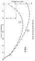
- ein den Einfederweg über dem Einschubmaß zeigendes Diagramm.
- Fig. 1
- a chair column with a gas spring in the vertical longitudinal section and
- Fig. 2
- a diagram showing the spring deflection above the insertion dimension.
Die in Fig. 1 dargestellte Stuhlsäule weist ein an einem Fußkreuz 1 angebrachtes Führungsrohr 2 auf, das an seinem oberen offenen Ende mit einer Führungsbüchse 3 versehen ist. In dem Führungsrohr 2 ist eine läugenverstellbare Gasfeder 4 angeordnet, deren Gehäuse 5 in der Führungsbüchse 3 in Richtung einer gemeinsamen Mittel-Längs-Achse 6 verschiebbar geführt angeordnet ist. Aus dem Gehäuse 5 ist nach unten eine Kolbenstange 7 herausgeführt, deren freies Ende mittels eines Axial-Lagers 8 auf einem Boden 9 des Führungsrohres 2 abgestützt und an diesem mittels eines Befestigungselementes 10 befestigt ist.The chair column shown in FIG. 1 has a
Das Gehäuse 5 der Gasfeder 4 weist einen Außenzylinder 11 und einen konzentrisch in diesem angeordneten Innen-Zylinder 12 auf. An der Innenwand 13 des Innenzylinders 12 liegt ein Kolben 14 abgedichtet an, der am inneren Ende der Kolbenstange 7 angebracht ist. Der Kolben 14 teilt den Innenzylinder 12 in zwei Gehäuseräume 15, 16.The
Die Kolbenstange 7 ist im Bereich ihres Austritts aus dem Gehäuse 5 in einer Führung 17 geführt, die gegenüber der Innenwand 18 des Außenzylinders 11 abgedichtet ist und in der eine Mehrfach-Lippen-Dichtung 19 angeordnet ist, die an der Kolbenstange 7 anliegt. Die Führung 17 ist mittels einer Umbördelung 20 des Außerzylinders 11 gehalten. Durch die geschilderte Ausgestaltung ist die Gasfeder 4 am Austritt der Kolbenstange 7 gas- und flüssigkeitsdicht verschlossen. Zum benachbarten Gehäuseraum 15 hin ist ein an der Führung 17 anliegender und die Dichtung 19 überdeckender Zentrierring 21 angeordnet, der einerseits an der Innenwand 18 des Außenzylinders 11 anliegt und dadurch zur Achse 6 zentriert ist und der andererseits einen den Innerzylinder 12 aufnehmenden und zur Achse 6 zentrierenden Zentrierbund 22 aufweist. Außerdem ist der Innenzylinder 12 in Richtung der Achse 6 am Zentrierring 21 abgestützt. Im Zentrierring 21 sind Verbindungskanäle 23 ausgebildet, die den zwischen dem Kolben 14 und dem kolbenstangenaustrittseitigen Ende des Gehäuses 5 ausgebildeten Gehäuseraum 15 mit einem zwischen dem Außenzylinder 11 und dem Innenzylinder 12 ausgebildeten spaltartigen ringförmigen Überströmkanal 24 verbinden.The
An dem dem Kolbenstangenaustritt entgegengesetzten Ende ist im Gehäuse 5 ein Ventil 25 angeordnet, dessen Ventilgehäuse 26 abgedichtet an der Innenwand 18 des Außenyzlinders 11 und der Innenwand 13 des Innenzylinders 12 anliegt und das mittels eines Zentrierbundes 27 den Innenzylinder 12 zur Achse 6 zentriert und das den Innenzylinder 12 in Richtung der Achse 6 abstützt. Das Ventilgehäuse 26 weist einen an den Überströmkanal 24 angeschlossenen Verbindungskanal 28 auf, der an einen konzentrisch zur Achse 6 im Ventilgehäuse 26 ausgebildeten Verbindungsraum 29 angeschlossen ist, der mit dem Gehäuseraum 16 zwischen dem Ventil 25 und dem Kolben 14 verbindbar ist. Zur Herstellung bzw. Sperrung dieser Verbindung ist ein Ventilstift 30 vorgesehen, der beim Einschieben in Richtung zum Gehäuseraum 16 eine Schließstelle 30a öffnet und damit den Verbindungsraum 29 mit dem Gehäuseraum 16 verbindet und der in seiner in der Zeichnung dargestellten Ruhelage die Schließstelle 30a schließt und damit den Verbindungsraum vom Gebäuseraum 16 trennt. Der Ventilstift 30 ist nach außen aus dem Ventilgehäuse 26 herausgeführt und liegt dort gegen einen Schieber 31 an, der in einem Befestigungsabschnitt 32 des Gehäuses 5 in Richtung der Achse 6 verschiebbar geführt und gehalten ist. Hierzu ist im Befestigungsabschnitt 32 ein Distanzstück 33 angeordnet, das durch eine Umbördelung 34 des Außenzylinders 11 gehalten ist. Dieses Distanzstück 33 hält auch das Ventil 25 in seiner axialen Lage. An diesem Befestigungsabschnitt 32 kann der Sitzträger eines Stuhles oder Sessels befestigt werden. Der Schieber 31 wird mittels eines Hebels oder dergleichen betätigt.At the end opposite the piston rod outlet, a
Die Gehäuseräume 15, 16 und die Verbindungskanäle 23, 28, der Verbindungsraum 29 und der Überströmkanal 24 sind mit Druckgas und gegebenenfalls etwas Öl gefüllt. Wenn das Ventil 25 geschlossen ist, kann die Kolbenstange 7 mit dem Kolben 14 relativ zum Gehäuse 5 federn. Wenn die Schließstelle 30a des Ventils 25 durch Einschieben des Ventilstiftes 30 in Richtung zum Gehäuseraum 16 geöffnet wird, dann kann entweder Gas aus dem Gehäuseraum 15 durch die Verbindungskanäle 23, den Überströmkanal 24, den Verbindungskanal 28 und den Verbindungsraum 29 in den Gehäuseraum 16 oder umgekehrt strömen, je nach dem, welche Kraft auf die Kolbenstange 7 in Richtung der Achse 6 wirkt. Der Aufbau der gesamten Stuhlsäule einschließlich der Gasfeder 5 und ihrer Wirkungsweise als Stuhl-Gasfeder mit Ausnahme der Ausgestaltung des Überströmkanals 27 sind bekannt, und zwar beispielsweise aus der grundlegenden DE-PS 18 12 282 (entspr. US-PS 3 656 593 und JP-PS 846 405).The
Der Überströmkanal 24 ist als ein extrem enger spaltartiger ringförmiger Überströmkanal ausgebildet, der ein extrem niedriges Volumen aufweist. Seine Spaltweite a ist sehr gering; bei einem üblichen Innendurchmesser b des Außenzylinders 11 von ca. 24 mm gilt a ≅ 0,1 mm. Dies gilt, wenn der Innendurchmesser c des Innenzylinders 12 c = 20 mm und der Durchmesser d der Kolbenstange d = 10 mm ist.The
Wesentlich ist, daß bei weitestmöglich aus dem Gehäuse 5 herausgefahrener Kolbenstange 7, also bei gemäß der Darstellung in Fig. 1 an dem Zentrierring 21 und damit der Führung 17 anliegendem Kolben 14, das Volumen VU der zwischen der Kolben-Unterseite 35 und der Schließstelle 30a ausgebildeten Gehäuseräume klein ist im Verhältnis zum Volumen VO des zwischen der Kolbenoberseite 36 und der Schließstelle 30a ausgebildeten Gehäuseraumes 16. Die Kolbenunterseite 35 ist dem Zentrierring 21 und der Führung 17 zugewandt; die Kolbenoberseite 36 ist dem Ventil 25 zugewandt. Bei geschlossenem Ventil wird das Volumen VU gebildet durch die verbleibenden Reste des Gehäuseraumes 15 und die Volumina der Verbindungskanäle 23, des Überströmkanals 24, des Verbindungskanals 28 und des Verbindungsraumes 29. Nur auf das Volumen des Überströmkanals 24 hat man konstruktiv nennenswerten Einfluß. Das Volumen VO ist gebildet durch den Gehäuseraum 16, der durch die dem Ventil 25 zugewandte Kolbenoberseite 36 einerseits und das Ventilgehäuse 26 bis zur Schließstelle 30a andererseits und naturgemäß die Innenwand 13 des Innenzylinders 12 begrenzt wird. Es gilt ![]()
![]()
![]()
![]()
![]()
![]()
![]()
![]()
Durch die geschilderte Ausgestaltung wird erreicht, daß die verfügbare Verstellänge der Gasfeder vergrößert wird. Dies sei unter anderem anhand des Diagramms nach Fig. 2 erläutert.The described design ensures that the available adjustment length of the gas spring is increased. This is explained, inter alia, using the diagram according to FIG. 2.
Für die untere mit 1 im Kreis gekennzeichnete Kurve gilt ![]()
![]()
Durch diese einer Last entsprechende Prüfkraft P federt die Kolbenstange jeweils um einen Weg s in das Gehäuse 5 ein. Dieser Einfederweg s ist in dem Diagramm nach Fig. 2 über dem Einschubmaß e jeweils in mm aufgetragen. Wenn das Ventil 25 bei voll ausgefahrener Kolbenstange 7 geschlossen wird, dann beträgt bei dem gewählten Beispiel der Einfederweg s nur 2 mm. Ein größerer Einfederweg s von etwa 4 mm ergibt sich, wenn das Ventil 25 bei einer leicht in das Gehäuse eingefahrenen Stellung der Kolbenstange 7 geschlossen wird, wobei diese Position so gewählt ist, daß bei der Entlastung der Kolbenstange 7 von der Einschubkraft die Kolbenstange 7 gerade noch wieder bis zum Anschlag der Kolbenunterseite 35 an der Führung 17 aus dem Gehäuse 5 ausgeschoben wird. Aus diesem Grunde hat das Diagramm ganz am Anfang einen senkrechten Abschnitt.As a result of this test force P corresponding to a load, the piston rod springs into the
Zum Vergleich ist in der mit 2 im Kreis gekennzeichneten Kurve in Fig. 2 der Einfederweg für eine gleichartige Gasfeder dargestellt, bei der gilt ![]()
![]()
![]()
![]()
Claims (4)
daß bei weitestmöglich aus dem Gehäuse (5) ausgefahrener Kolbenstange (7) für das Volumen (VO) des Gehäuseraumes (16) zwischen der Schließstelle (30a) des Ventils (25) und der Kolbenoberseite (36) im Verhältnis zum Volumen (VU) des Gehäusraumes (15) zwischen Kolbenunterseite (35) und Führung (17), des mindestens einen Verbindungskanals (23), des Überströmkanals (24) und des Raumes im Ventil (25) bis zu Schließstelle (30a) gilt
that as far as possible from the housing (5) extended piston rod (7) for the volume (V O ) of the housing space (16) between the closing point (30a) of the valve (25) and the piston top (36) in relation to the volume (V U ) of the housing space (15) between the underside of the piston (35) and the guide (17), the at least one connecting channel (23), the overflow channel (24) and the space in the valve (25) up to the closing point (30a)
Applications Claiming Priority (2)
| Application Number | Priority Date | Filing Date | Title |
|---|---|---|---|
| DE29608147U | 1996-05-04 | ||
| DE29608147U DE29608147U1 (en) | 1996-05-04 | 1996-05-04 | Chair gas spring |
Publications (3)
| Publication Number | Publication Date |
|---|---|
| EP0804889A2 true EP0804889A2 (en) | 1997-11-05 |
| EP0804889A3 EP0804889A3 (en) | 1999-12-29 |
| EP0804889B1 EP0804889B1 (en) | 2003-06-18 |
Family
ID=8023569
Family Applications (1)
| Application Number | Title | Priority Date | Filing Date |
|---|---|---|---|
| EP97106443A Expired - Lifetime EP0804889B1 (en) | 1996-05-04 | 1997-04-18 | Gas spring for a chair |
Country Status (6)
| Country | Link |
|---|---|
| EP (1) | EP0804889B1 (en) |
| JP (1) | JPH1061703A (en) |
| KR (1) | KR100456220B1 (en) |
| DE (2) | DE29608147U1 (en) |
| ES (1) | ES2201218T3 (en) |
| TW (1) | TW349614U (en) |
Cited By (1)
| Publication number | Priority date | Publication date | Assignee | Title |
|---|---|---|---|---|
| WO2002077497A1 (en) * | 2001-03-23 | 2002-10-03 | Montajes Mecanicos Lezo, S.L. | Gas cylinder with a double jacket |
Families Citing this family (3)
| Publication number | Priority date | Publication date | Assignee | Title |
|---|---|---|---|---|
| DE19809389C1 (en) | 1998-03-05 | 1999-10-07 | Stabilus Gmbh | Length adjustable pillar for seat support |
| KR100478652B1 (en) * | 2002-09-10 | 2005-03-23 | 정의협 | Length Adjustable Gas Spring |
| DE102015209465A1 (en) | 2015-05-22 | 2016-11-24 | Sedus Stoll Ag | Gas spring device for height adjustment of a chair and chair with such a gas spring device |
Family Cites Families (6)
| Publication number | Priority date | Publication date | Assignee | Title |
|---|---|---|---|---|
| DE1554201B1 (en) * | 1965-02-25 | 1971-07-01 | Fichtel & Sachs Ag | Hydropneumatic lifting unit, especially for stepless height adjustment of table tops and chairs |
| DE1812282C3 (en) * | 1968-12-03 | 1981-07-30 | Fritz Bauer + Söhne oHG, 8503 Altdorf | Lifting device for stepless height adjustment of table tops, chair seats and the like. |
| DE2907100A1 (en) * | 1979-02-23 | 1980-08-28 | Bauer Fritz & Soehne Ohg | LENGTH ADJUSTABLE GAS SPRINGS |
| US4834347A (en) * | 1988-04-20 | 1989-05-30 | Grazina J. Pauliukonis | Positioner with large diameter piston rod and fluted volume-compensating piston |
| DE4009034A1 (en) * | 1990-03-21 | 1991-09-26 | Suspa Federungstech | LENGTH ADJUSTABLE GAS SPRINGS |
| DE4420914A1 (en) * | 1994-06-16 | 1995-12-21 | Suspa Compart Ag | Length-adjustable gas spring and length-adjustable column for chairs, tables with a length-adjustable gas spring |
-
1996
- 1996-05-04 DE DE29608147U patent/DE29608147U1/en not_active Expired - Lifetime
-
1997
- 1997-04-18 EP EP97106443A patent/EP0804889B1/en not_active Expired - Lifetime
- 1997-04-18 ES ES97106443T patent/ES2201218T3/en not_active Expired - Lifetime
- 1997-04-18 DE DE59710291T patent/DE59710291D1/en not_active Expired - Lifetime
- 1997-04-28 TW TW086206730U patent/TW349614U/en unknown
- 1997-04-30 KR KR1019970016525A patent/KR100456220B1/en not_active Expired - Fee Related
- 1997-05-01 JP JP9113910A patent/JPH1061703A/en active Pending
Cited By (2)
| Publication number | Priority date | Publication date | Assignee | Title |
|---|---|---|---|---|
| WO2002077497A1 (en) * | 2001-03-23 | 2002-10-03 | Montajes Mecanicos Lezo, S.L. | Gas cylinder with a double jacket |
| US6886671B2 (en) | 2001-03-23 | 2005-05-03 | Gain Gas Technique, S.L. | Gas cylinder with a double jacket |
Also Published As
| Publication number | Publication date |
|---|---|
| JPH1061703A (en) | 1998-03-06 |
| ES2201218T3 (en) | 2004-03-16 |
| EP0804889A3 (en) | 1999-12-29 |
| DE29608147U1 (en) | 1996-08-01 |
| KR970075455A (en) | 1997-12-10 |
| DE59710291D1 (en) | 2003-07-24 |
| KR100456220B1 (en) | 2005-01-26 |
| TW349614U (en) | 1999-01-01 |
| EP0804889B1 (en) | 2003-06-18 |
Similar Documents
| Publication | Publication Date | Title |
|---|---|---|
| DE3738298C2 (en) | Length-adjustable gas spring for height-adjustable chairs | |
| DE2408052C3 (en) | Length-adjustable gas spring | |
| DE69009754T2 (en) | DOSING VALVE FOR AEROSOL CONTAINERS. | |
| DE69016218T2 (en) | Hydraulically lockable gas spring. | |
| DE2164943C3 (en) | Hydraulically lockable lifting device | |
| DE2341352C2 (en) | Blockable lifting unit with end suspension | |
| DE19827657A1 (en) | Adjustable gas spring | |
| EP1403549A2 (en) | Length-adjustable compression spring | |
| DE2312445B2 (en) | Hydraulic shock absorber | |
| DE3210112A1 (en) | DEVICE FOR CARRYING A SEAT AT A PREDICTED HEIGHT | |
| DE3616438A1 (en) | HYDROPNEUMATIC ADJUSTMENT | |
| EP1526301B1 (en) | Compression spring with adjustable length and seat with such a spring | |
| DE1925963A1 (en) | Gas spring | |
| EP1525144B1 (en) | Pressure control valve | |
| EP2807963A1 (en) | Espresso coffee machine with a brewing unit | |
| DE10163996A1 (en) | Adjustable gas spring | |
| DE7825656U1 (en) | Gas spring | |
| EP1736682B1 (en) | Lengthwise adjustable gas spring | |
| DE2744917A1 (en) | STRAIGHT PASS VALVE | |
| EP1741843A2 (en) | Backflow prevention assembly | |
| DE3630911C2 (en) | ||
| EP1557114B1 (en) | Height adjustable chair column | |
| DE9204971U1 (en) | Spring element | |
| EP0804889B1 (en) | Gas spring for a chair | |
| DE102007012838B3 (en) | Gas spring e.g. for office seating, has stop piston positioned between valve unit and guide-piston |
Legal Events
| Date | Code | Title | Description |
|---|---|---|---|
| PUAI | Public reference made under article 153(3) epc to a published international application that has entered the european phase |
Free format text: ORIGINAL CODE: 0009012 |
|
| AK | Designated contracting states |
Kind code of ref document: A2 Designated state(s): DE ES FR GB IT |
|
| PUAL | Search report despatched |
Free format text: ORIGINAL CODE: 0009013 |
|
| AK | Designated contracting states |
Kind code of ref document: A3 Designated state(s): DE ES FR GB IT |
|
| RIC1 | Information provided on ipc code assigned before grant |
Free format text: 6A 47C 3/30 A, 6F 16F 9/02 B |
|
| 17P | Request for examination filed |
Effective date: 19991214 |
|
| RAP1 | Party data changed (applicant data changed or rights of an application transferred) |
Owner name: SUSPA HOLDING GMBH |
|
| 17Q | First examination report despatched |
Effective date: 20011003 |
|
| GRAH | Despatch of communication of intention to grant a patent |
Free format text: ORIGINAL CODE: EPIDOS IGRA |
|
| GRAH | Despatch of communication of intention to grant a patent |
Free format text: ORIGINAL CODE: EPIDOS IGRA |
|
| RAP1 | Party data changed (applicant data changed or rights of an application transferred) |
Owner name: SUSPA COMPART GMBH |
|
| GRAA | (expected) grant |
Free format text: ORIGINAL CODE: 0009210 |
|
| AK | Designated contracting states |
Designated state(s): DE ES FR GB IT |
|
| REG | Reference to a national code |
Ref country code: GB Ref legal event code: FG4D Free format text: NOT ENGLISH |
|
| GBT | Gb: translation of ep patent filed (gb section 77(6)(a)/1977) | ||
| REF | Corresponds to: |
Ref document number: 59710291 Country of ref document: DE Date of ref document: 20030724 Kind code of ref document: P |
|
| ET | Fr: translation filed | ||
| RAP2 | Party data changed (patent owner data changed or rights of a patent transferred) |
Owner name: SUSPA HOLDING GMBH |
|
| REG | Reference to a national code |
Ref country code: ES Ref legal event code: FG2A Ref document number: 2201218 Country of ref document: ES Kind code of ref document: T3 |
|
| PLBE | No opposition filed within time limit |
Free format text: ORIGINAL CODE: 0009261 |
|
| STAA | Information on the status of an ep patent application or granted ep patent |
Free format text: STATUS: NO OPPOSITION FILED WITHIN TIME LIMIT |
|
| 26N | No opposition filed |
Effective date: 20040319 |
|
| PGFP | Annual fee paid to national office [announced via postgrant information from national office to epo] |
Ref country code: GB Payment date: 20050407 Year of fee payment: 9 |
|
| PG25 | Lapsed in a contracting state [announced via postgrant information from national office to epo] |
Ref country code: GB Free format text: LAPSE BECAUSE OF NON-PAYMENT OF DUE FEES Effective date: 20060418 |
|
| PGFP | Annual fee paid to national office [announced via postgrant information from national office to epo] |
Ref country code: IT Payment date: 20060430 Year of fee payment: 10 |
|
| GBPC | Gb: european patent ceased through non-payment of renewal fee |
Effective date: 20060418 |
|
| PGFP | Annual fee paid to national office [announced via postgrant information from national office to epo] |
Ref country code: ES Payment date: 20080424 Year of fee payment: 12 |
|
| PGFP | Annual fee paid to national office [announced via postgrant information from national office to epo] |
Ref country code: FR Payment date: 20080418 Year of fee payment: 12 |
|
| PG25 | Lapsed in a contracting state [announced via postgrant information from national office to epo] |
Ref country code: IT Free format text: LAPSE BECAUSE OF NON-PAYMENT OF DUE FEES Effective date: 20070418 |
|
| REG | Reference to a national code |
Ref country code: FR Ref legal event code: ST Effective date: 20091231 |
|
| PG25 | Lapsed in a contracting state [announced via postgrant information from national office to epo] |
Ref country code: FR Free format text: LAPSE BECAUSE OF NON-PAYMENT OF DUE FEES Effective date: 20091222 |
|
| REG | Reference to a national code |
Ref country code: ES Ref legal event code: FD2A Effective date: 20090420 |
|
| PG25 | Lapsed in a contracting state [announced via postgrant information from national office to epo] |
Ref country code: ES Free format text: LAPSE BECAUSE OF NON-PAYMENT OF DUE FEES Effective date: 20090420 |
|
| PGFP | Annual fee paid to national office [announced via postgrant information from national office to epo] |
Ref country code: DE Payment date: 20100430 Year of fee payment: 14 |
|
| REG | Reference to a national code |
Ref country code: DE Ref legal event code: R119 Ref document number: 59710291 Country of ref document: DE |
|
| REG | Reference to a national code |
Ref country code: DE Ref legal event code: R119 Ref document number: 59710291 Country of ref document: DE |
|
| PG25 | Lapsed in a contracting state [announced via postgrant information from national office to epo] |
Ref country code: DE Free format text: LAPSE BECAUSE OF NON-PAYMENT OF DUE FEES Effective date: 20111031 |