EP0804895B1 - Support pour une unité de travail pour une machine domestique électrique - Google Patents
Support pour une unité de travail pour une machine domestique électrique Download PDFInfo
- Publication number
- EP0804895B1 EP0804895B1 EP97102927A EP97102927A EP0804895B1 EP 0804895 B1 EP0804895 B1 EP 0804895B1 EP 97102927 A EP97102927 A EP 97102927A EP 97102927 A EP97102927 A EP 97102927A EP 0804895 B1 EP0804895 B1 EP 0804895B1
- Authority
- EP
- European Patent Office
- Prior art keywords
- bearing sleeve
- support member
- base plate
- bearing
- sleeve
- Prior art date
- Legal status (The legal status is an assumption and is not a legal conclusion. Google has not performed a legal analysis and makes no representation as to the accuracy of the status listed.)
- Expired - Lifetime
Links
- 230000003014 reinforcing effect Effects 0.000 claims abstract 12
- 239000002184 metal Substances 0.000 claims description 11
- 238000000034 method Methods 0.000 claims description 7
- 238000005096 rolling process Methods 0.000 claims description 3
- 230000002093 peripheral effect Effects 0.000 abstract 1
- 238000003756 stirring Methods 0.000 description 5
- 235000013305 food Nutrition 0.000 description 4
- 238000004519 manufacturing process Methods 0.000 description 3
- 210000002105 tongue Anatomy 0.000 description 3
- 230000007704 transition Effects 0.000 description 3
- 239000011324 bead Substances 0.000 description 2
- 238000005452 bending Methods 0.000 description 2
- 239000000463 material Substances 0.000 description 2
- 238000003825 pressing Methods 0.000 description 2
- 230000005540 biological transmission Effects 0.000 description 1
- 230000015572 biosynthetic process Effects 0.000 description 1
- 238000010276 construction Methods 0.000 description 1
- 238000005520 cutting process Methods 0.000 description 1
- 238000013016 damping Methods 0.000 description 1
- 238000010790 dilution Methods 0.000 description 1
- 239000012895 dilution Substances 0.000 description 1
- 238000009429 electrical wiring Methods 0.000 description 1
- 239000004744 fabric Substances 0.000 description 1
- 235000021478 household food Nutrition 0.000 description 1
- 230000002787 reinforcement Effects 0.000 description 1
Images
Classifications
-
- A—HUMAN NECESSITIES
- A47—FURNITURE; DOMESTIC ARTICLES OR APPLIANCES; COFFEE MILLS; SPICE MILLS; SUCTION CLEANERS IN GENERAL
- A47J—KITCHEN EQUIPMENT; COFFEE MILLS; SPICE MILLS; APPARATUS FOR MAKING BEVERAGES
- A47J43/00—Implements for preparing or holding food, not provided for in other groups of this subclass
- A47J43/04—Machines for domestic use not covered elsewhere, e.g. for grinding, mixing, stirring, kneading, emulsifying, whipping or beating foodstuffs, e.g. power-driven
- A47J43/07—Parts or details, e.g. mixing tools, whipping tools
- A47J43/08—Driving mechanisms
- A47J43/085—Driving mechanisms for machines with tools driven from the lower side
-
- A—HUMAN NECESSITIES
- A47—FURNITURE; DOMESTIC ARTICLES OR APPLIANCES; COFFEE MILLS; SPICE MILLS; SUCTION CLEANERS IN GENERAL
- A47J—KITCHEN EQUIPMENT; COFFEE MILLS; SPICE MILLS; APPARATUS FOR MAKING BEVERAGES
- A47J43/00—Implements for preparing or holding food, not provided for in other groups of this subclass
- A47J43/04—Machines for domestic use not covered elsewhere, e.g. for grinding, mixing, stirring, kneading, emulsifying, whipping or beating foodstuffs, e.g. power-driven
- A47J43/07—Parts or details, e.g. mixing tools, whipping tools
- A47J43/0716—Parts or details, e.g. mixing tools, whipping tools for machines with tools driven from the lower side
Definitions
- the present invention relates to a carrier for a drive system electrically powered household appliance according to the preamble of claim 1.
- Electric kitchen machine is known for example from DE-31 26 956 C2.
- This device which is a shredder or a shredder, the is also suitable for stirring, has a bottom plate with a side circumferential edge, to which a housing main body adjoins at the top.
- a plate-shaped carrier which has an electric drive motor on its top with a shaft that extends through the carrier to the bottom extends.
- the carrier that carries the individual parts is a thin, flat metal plate made of sheet metal that generates forces and vibrations when the device is in operation Must record and this in particular in the bearing sleeves.
- the Bearing sleeve bearing spindle placed as a separate component on the base plate in order to in this way to achieve a sufficient bearing length to absorb the bearing forces.
- the present Invention the object of a carrier for the drive system of an electric to create driven household appliance, in particular for a food processor, the on the one hand has a high rigidity, on the other hand from as few parts as possible exists and is also inexpensive and lightweight.
- Such a carrier after the invention is characterized by a high rigidity, in particular by the several, bead-shaped stiffening ribs can be achieved on the bearing sleeves. Because a simple sheet metal support can be selected precisely through these stiffening ribs, on which the bearing sleeves are integrated in one piece in the carrier and on one opposite State of the art can be brought much longer stock length without the Bearing forces cause an early break.
- the stiffening ribs run radiating to the axis of the at least one bearing sleeve and going into the sleeve wall over and run out in it.
- This radial arrangement of the stiffening ribs can the transverse forces that occur via the stiffening ribs in the Base plate can be initiated without damage.
- the entire carrier can thus be made of thin-walled Material are made.
- the stiffening ribs are an extension of the bearing sleeves possible, which improves the length of the bearing and thus the stability the camp increased.
- the beads on the outer circumference of the Be bearing sleeve formed. This has the advantage that to accommodate a plain bearing bush in the bearing sleeve, this is the largest possible receiving surface for the plain bearing bush has, which is then held extremely stable in the bearing sleeve.
- the plain bearing bush serves as a plain bearing for a drive spindle or shaft.
- the cylindrical part of the bearing sleeve is large held in order to press the bearing bush as firmly as possible into the bearing sleeve.
- a continuous stiffening rib reduces the proportion of wearing Bearing bush, but can simplify the production of the bearing sleeves, because of the ribs then can also be pulled and calibrated.
- the bearing sleeves must have different heights have in the axial direction of the shaft or spindle or the bearing. So even with longer, Adequate rigidity higher above the base plate to ensure against transverse forces acting on the sleeve wall should according to Claim 6 the stiffening ribs not only in the wall of the respective bearing sleeve pass, but also a certain length along the sleeve wall of the bearing sleeve extend. They preferably end at a height above the base plate, which is approximately the double the height of the respective rib, i.e. the cross-sectional height of the rib. It has been shown that the lateral forces are sufficient with such a dimensioning have it recorded.
- the features of the Claims 7 to 11 are provided.
- To a carrier with the features of the invention To form in one piece from metal (claim 8) should preferably be different Deformation steps are applied to form the bearing sleeves and the ribs.
- To form the bearing sleeves in one piece from a thin sheet first of all the bearing sleeves formed by rolling (claim 10) by the plate material rolling until the corresponding bearing sleeve is pulled.
- the free edge of the bearing sleeve are rolled out very thin to the appropriate length the bearing sleeve with which it protrudes above the level of the base plate.
- the ribs are then drawn by deep drawing according to claim 10 or Pressing formed according to claim 11 at the predetermined locations, which then also in merging the wall of the bearing sleeve and extending along it can be.
- a sheet thickness of preferably about 0.5 to 1.5 mm is used, with a thickness of about 1 mm being preferred.
- a beam with the stiffening ribs is also made of Plastic could be molded with or without fabric reinforcement, however, is a Carrier made of a sheet metal (claim 8) to be preferred, as this makes an even higher one Torsional rigidity of the entire beam at the cheapest price and easier Manufacturing can be achieved.
- the height of the sleeve itself, with which it protrudes above the level of the base plate, should according to claim 12 about 1 to 2 times, preferably 1.5 times the Sleeve inside diameter. It has been shown that such a level of Sleeve is sufficient to hold the appropriate spindles and shafts in a kitchen appliance are needed to hold and store, especially when the Carrier is formed from metal and the bearing sleeves in one piece from a thin metal sheet according to claim 9, including the stiffening ribs.
- the stiffening ribs are evenly on the Distributed circumference of each bearing sleeve, preferably three stiffening ribs each Bearing sleeve are assigned. With this arrangement, the forces can be evenly in initiated in various directions in the main plane of the base plate without damage become.
- the carrier described above can as a one-piece component all requirements pose in particular in a kitchen appliance. Especially when Several bearings can be provided for additional drive shafts or spindles must, as is the case, for example, in kitchen machines with two stirring or crushing tools, the different containers are assigned, the case can these additional bearing points are shaped out of the base plate in the form of bearing sleeves are then pressed into the sliding sleeves for the shafts. To even then To maintain the required stiffness, the stiffening ribs are made accordingly distributed over the carrier and at least ribs, radiating from the respective Starting sleeves, molded out of the carrier. This results in a Inexpensive and easy to assemble part, despite the thin-walled construction a high bending and torsional rigidity due to the stiffening ribs and if necessary due to the edge surrounding the base plate at least partially.
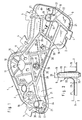
- the carrier 1 as shown in FIG. 1 from its top, has a base plate 2, which runs in one plane with its flat surface elements. All around the Base plate 2 is a slightly protruding edge 3 above its level, which approximately perpendicular to the plane of the base plate 2 is formed. Are in several places Support tongues 4 for storing the carrier 1 in a device housing, not shown provided on corresponding, to be provided.
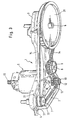
- the carrier as it is shown in FIGS. 1 and 3, is used according to FIG electric drive motor 5 with drive shaft 12, a first drive spindle 6, a second drive spindle 7 and a shaft 8 for a tensioning wheel 9.
- the first and second drive spindle 6, 7 is rotatably connected to a pulley 31 or 32.
- the drive parts are shown in their state mounted on the carrier 1 in FIG. 3, which, in contrast to FIG. 1, shows a view of the carrier 1 from the underside thereof.
- An opening 10 is formed in the base plate 2 for the electric drive motor 5, which is surrounded by three elongated holes 11, by the fastening screws, not shown be passed through for mounting the drive motor 5.
- By the opening 10 extends the drive shaft 12 of the drive motor 5 freely, which carries a drive pinion 13 (see Fig. 3) which, like the pulleys 31, 32, in engages a drive V-belt 14.
- the Opening 10 surrounds and in which the elongated holes 11 for fastening the drive motor 5 are provided to stiffen, there are several bead-shaped stiffening ribs 15 evenly distributed from the edge of the opening 10, covering the area Stiffen around the opening 10. A total of five such beads are here Stiffening ribs 15 are provided around the opening 10.
- the carrier 1 has a first bearing sleeve 16 and one second bearing sleeve 17 each.
- the first bearing sleeve 16 is provided for the first Drive spindle 6 via a bearing bush 30 (FIG. 2) to be inserted into the sleeve store, while the second bearing sleeve 17 is provided, the second drive spindle 7, also by means of a corresponding bearing bush, not shown slidably rotatable.
- the bearing sleeve 16 of FIG. 1 is shown in section in FIG. 2. As with FIG. 2 can be seen, the first bearing sleeve 16 is above the base plate 2 of the carrier 1 in Direction of the axis 18 seen at a height 19 which is about 2 to 5 times the inner diameter 20 corresponds to the first bearing sleeve 16, before, preferably approximately that 3.2 times.
- the second bearing sleeve 16 also corresponds to this ratio Bearing sleeve 17 dimensioned.
- the inner diameter is advantageously 20 Bearing sleeve 17 about 14 mm, the height 20 mm, the protruding bearing Length of the entire bearing bush (not shown) 27 mm and its inner diameter about 8 mm.
- stiffening ribs 21 extend radially from the Sleeve wall 22 to the outside.
- four such stiffening ribs 21 are assigned, extend from the second, somewhat smaller Bearing sleeve 17 only three such stiffening ribs 21 radially outwards.
- These stiffening ribs 21 go, as the sectional view of FIG. 2 shows at the transition 33, into the sleeve wall 22 each; they end at a height 23 above the base plate 2, which corresponds approximately to twice the height 24 of the stiffening ribs 21 (FIG. 2). This Arrangement is sufficient here to make the bearing sleeves sufficiently rigid.
- the Cross-sectional height 24 of the stiffening ribs 21 is approximately 5 mm here.
- stiffening ribs radiating into the first and second bearing sleeves 16, 17 21 becomes the very long and thin-walled sleeve wall 22 by the deep-drawing process stiffened.
- the bearing sleeves 16 and 17 a to impart additional rigidity so extend from the bearing sleeves 16, 17th radially extending stiffening ribs 21 to the edge 3 of the carrier 1 and run in this edge 3, as is particularly clear in FIG. 1 on the basis of the front stiffening rib 21, which starts from the second bearing sleeve 17, can be seen. From underneath forth or viewed from the edge, the stiffening rib 21 forms a groove 34.
- the base plate 2 is made of a thin metal sheet with a wall thickness in the range of approximately 0.8 mm to 1.2 mm, preferably 1 mm, shaped when for a household food processor with a drive power of Drive motor 5 of about 300 to 500 watts is used.
- the base plate 2 In order to manufacture the base plate 2, as shown in FIG. 1, after the Stamping process first the first bearing sleeve 16, the second bearing sleeve 17 and the further bearing sleeve 25 in a deformation or deep-drawing process with dilution of the plate-shaped sheet metal blank that is used for the carrier 1 to the Bearing area areas.
- the upper edge of the respective sleeve 16, 17 and 25 bent to a wall thickness of a few tenths of a millimeter until the bearing sleeves 16, 17, 25 break open at their openings 35, 36, 37.
- the carrier 1 produced in this way is easy to install, particularly inexpensive Component that also has a high rigidity due to the base plate 2, to absorb the forces occurring in a food processor without damage.
- one side of a cable clamp 38 is also molded into the base plate 2, which is used to attach the connection cable (not shown). Still is still formed a contact lug 39 in the base plate 2 for grounding.
Landscapes
- Engineering & Computer Science (AREA)
- Mechanical Engineering (AREA)
- Food Science & Technology (AREA)
- Food-Manufacturing Devices (AREA)
- Mounting Of Bearings Or Others (AREA)
- Catching Or Destruction (AREA)
- Massaging Devices (AREA)
- Cookers (AREA)
- Handcart (AREA)
- Crushing And Pulverization Processes (AREA)
Claims (13)
- Support (1) pour un système d'entraínement d'un appareil ménager mû électriquement, notamment d'un appareil de cuisine, comportant une plaque de base (2), qui comporte un dispositif de retenue pour un moteur électrique et au moins une douille de support (16; 17), qui fait saillie sur la plaque de base (2) et sert à loger un coussinet de palier (30) pour supporter avec possibilité de rotation une broche d'entraínement (6; 7), la douille de support (16; 17) étant réalisée d'un seul tenant avec la plaque de base (2) et s'étendant essentiellement transversalement par rapport à la plaque de base (2), caractérisé en ce que la plaque de base (2) comporte au moins une nervure de rigidification en forme de moulure (21), que la nervure de renforcement (21) s'étend selon un rayon par rapport à au moins une douille de support (16; 17) et que cette nervure de renforcement (21) se prolonge par la paroi (22) de la douille de support (16; 17).
- Support selon la revendication 1, caractérisé en ce que la nervure de renforcement en forme de moulure (21) fait saillie sur la périphérie extérieure de la douille de support (16, 17).
- Support selon la revendication 1, caractérisé en ce que la nervure de renforcement en forme de moulure (21) fait saillie sur la périphérie intérieure de la douille de support (16, 17).
- Support selon la revendication 1, caractérisé en ce que la nervure de renforcement (21) se termine dans la douille de support (16, 17).
- Support selon la revendication 1, caractérisé en ce que la nervure de renforcement (21) traverse la douille de support (16, 17).
- Support selon la revendication 1, caractérisé en ce que la nervure de renforcement (21) possède une étendue dans la direction de l'axe (18) de la douille de support (16; 17) le long de la paroi (22) de la douille et qu'elle se termine à une hauteur (23) au-dessus de la plaque de base (2) de telle sorte que cette hauteur correspond approximativement au double de la hauteur (24) de la nervure respective (21).
- Support selon la revendication 1, caractérisé en ce que la plaque de base (2) comporte un bord au moins en partie périphérique, qui fait saillie sur le côté s'étendant du côté de la nervure de renforcement (21), et dans lequel une partie de la nervure (21) se termine dans ce bord (3).
- Support selon la revendication 1, caractérisé en ce qu'il est formé d'un métal.
- Support selon la revendication 8, caractérisé en ce que la douille de support (16; 17; 25) est formée par une déformation par laminage.
- Support selon la revendication 8, caractérisé en ce que la nervure est formée par emboutissage.
- Support selon la revendication 8, caractérisé en ce que la nervure (15, 21, 28) est insérée à force dans la plaque de base (2).
- Support selon la revendication 1, caractérisé en ce que la douille (16; 17) fait saillie au-dessus de la plaque de base (2) environ sur une hauteur comprise entre 1 et 2 fois et de préférence égale à 1,5 fois le diamètre intérieur (20) de la douille.
- Support selon la revendication 1, caractérisé en ce qu'à chaque douille de support (16; 17) sont associées au moins trois nervures de renforcement (21), qui sont réparties approximativement à des distances réciproques identiques autour de la périphérie de la douille de support respective (16; 17).
Applications Claiming Priority (2)
| Application Number | Priority Date | Filing Date | Title |
|---|---|---|---|
| DE19617139 | 1996-04-29 | ||
| DE19617139A DE19617139A1 (de) | 1996-04-29 | 1996-04-29 | Träger für ein Antriebssystem eines elektrisch angetriebenen Haushaltsgerätes |
Publications (2)
| Publication Number | Publication Date |
|---|---|
| EP0804895A1 EP0804895A1 (fr) | 1997-11-05 |
| EP0804895B1 true EP0804895B1 (fr) | 2002-11-13 |
Family
ID=7792808
Family Applications (1)
| Application Number | Title | Priority Date | Filing Date |
|---|---|---|---|
| EP97102927A Expired - Lifetime EP0804895B1 (fr) | 1996-04-29 | 1997-02-22 | Support pour une unité de travail pour une machine domestique électrique |
Country Status (4)
| Country | Link |
|---|---|
| EP (1) | EP0804895B1 (fr) |
| AT (1) | ATE227539T1 (fr) |
| DE (2) | DE19617139A1 (fr) |
| ES (1) | ES2187691T3 (fr) |
Families Citing this family (2)
| Publication number | Priority date | Publication date | Assignee | Title |
|---|---|---|---|---|
| DE19645305A1 (de) * | 1996-11-04 | 1998-05-20 | Braun Ag | Antriebssystem für eine elektrisch angetriebene Küchenmaschine |
| FR2814662B1 (fr) * | 2000-10-04 | 2002-12-20 | Seb Sa | Dispositif anti-patinage pour appareil electromenager de preparation culinaire comportant une transmission par courroie |
Family Cites Families (5)
| Publication number | Priority date | Publication date | Assignee | Title |
|---|---|---|---|---|
| NO143987C (no) * | 1976-04-01 | 1981-05-27 | Zyliss Zysset Ag Ind | Apparat, saerlig husholdningsapparat, for oppdeling av skjaerbare gjenstander, saerlig kjoett, loek og liknende |
| DE7900590U1 (de) * | 1979-01-11 | 1979-04-19 | Vorwerk & Co Interholding Gmbh, 5600 Wuppertal | Deckel fuer beheizbare haushaltsmixer |
| JPS5720932U (fr) * | 1980-07-09 | 1982-02-03 | ||
| EP0549818B1 (fr) * | 1992-01-01 | 1995-09-20 | Maweva Holding Ag | Appareil de cuisine |
| DE4215882A1 (de) * | 1992-05-14 | 1993-11-18 | Braun Ag | Küchenmaschine |
-
1996
- 1996-04-29 DE DE19617139A patent/DE19617139A1/de not_active Withdrawn
-
1997
- 1997-02-22 ES ES97102927T patent/ES2187691T3/es not_active Expired - Lifetime
- 1997-02-22 AT AT97102927T patent/ATE227539T1/de not_active IP Right Cessation
- 1997-02-22 DE DE59708689T patent/DE59708689D1/de not_active Expired - Fee Related
- 1997-02-22 EP EP97102927A patent/EP0804895B1/fr not_active Expired - Lifetime
Also Published As
| Publication number | Publication date |
|---|---|
| DE19617139A1 (de) | 1997-11-06 |
| ATE227539T1 (de) | 2002-11-15 |
| DE59708689D1 (de) | 2002-12-19 |
| EP0804895A1 (fr) | 1997-11-05 |
| ES2187691T3 (es) | 2003-06-16 |
Similar Documents
| Publication | Publication Date | Title |
|---|---|---|
| DE69737869T2 (de) | Getriebemotor, insbesondere zum Antrieb von Zubehörteilen in Kraftfahrzeugen | |
| DE3017314C2 (de) | Universalgelenk | |
| DE69702541T2 (de) | Wälzlager für kraftfahrzeuglenksäulen | |
| DE3608507C2 (fr) | ||
| DE3729574C2 (fr) | ||
| DE69619756T2 (de) | Verbesserte Kreissäge | |
| EP1502346B1 (fr) | Sous-groupe de moteur bldc | |
| EP0792724A1 (fr) | Boîtier pour un outil à main entraîné par un moteur | |
| DE19857033B4 (de) | Axiallager | |
| DE102020131946B4 (de) | Getriebevorrichtung mit Ölfangschale | |
| EP0804895B1 (fr) | Support pour une unité de travail pour une machine domestique électrique | |
| DE19540123C2 (de) | Getriebegehäuse | |
| DE2453181A1 (de) | Spindelhalterung fuer die spindel eines kreiselmaehers | |
| DE69818336T2 (de) | Servolenkung | |
| DE102013210074A1 (de) | Antriebseinrichtung | |
| EP4176182A1 (fr) | Transmission comprenant un boîtier présentant une partie inférieure et une partie couvercle | |
| DE102008040029B4 (de) | Rotor für einen Elektromotor | |
| DE60107161T2 (de) | Trägerplatte für eine Kraftfahrzeugtür mit integrierter Fassung für einen Fensterheberantrieb | |
| DE102007033748A1 (de) | Trommelwaschmaschine | |
| EP1163082B1 (fr) | Meuleuse d'angle | |
| DE10208538B4 (de) | Wischeranlage mit einer Platine | |
| DE3521342C1 (de) | Elektromotor mit einem Motorgehaeuse und einem daran befestigten Getriebegehaeuse | |
| EP1335479A2 (fr) | Dispositif de fixation d'un moteur électrique permettant une isolation contre les vibrations | |
| DE4026549C2 (de) | Von vorn beschickbare Waschmaschine | |
| EP2114225B1 (fr) | Palier à glissement destiné à un appareil ménager |
Legal Events
| Date | Code | Title | Description |
|---|---|---|---|
| PUAI | Public reference made under article 153(3) epc to a published international application that has entered the european phase |
Free format text: ORIGINAL CODE: 0009012 |
|
| AK | Designated contracting states |
Kind code of ref document: A1 Designated state(s): AT CH DE ES FR GB LI NL |
|
| 17P | Request for examination filed |
Effective date: 19971121 |
|
| RAP1 | Party data changed (applicant data changed or rights of an application transferred) |
Owner name: BRAUN GMBH |
|
| GRAG | Despatch of communication of intention to grant |
Free format text: ORIGINAL CODE: EPIDOS AGRA |
|
| 17Q | First examination report despatched |
Effective date: 20020307 |
|
| GRAG | Despatch of communication of intention to grant |
Free format text: ORIGINAL CODE: EPIDOS AGRA |
|
| GRAH | Despatch of communication of intention to grant a patent |
Free format text: ORIGINAL CODE: EPIDOS IGRA |
|
| GRAH | Despatch of communication of intention to grant a patent |
Free format text: ORIGINAL CODE: EPIDOS IGRA |
|
| GRAA | (expected) grant |
Free format text: ORIGINAL CODE: 0009210 |
|
| AK | Designated contracting states |
Kind code of ref document: B1 Designated state(s): AT CH DE ES FR GB LI NL |
|
| PG25 | Lapsed in a contracting state [announced via postgrant information from national office to epo] |
Ref country code: NL Free format text: LAPSE BECAUSE OF FAILURE TO SUBMIT A TRANSLATION OF THE DESCRIPTION OR TO PAY THE FEE WITHIN THE PRESCRIBED TIME-LIMIT Effective date: 20021113 Ref country code: GB Free format text: LAPSE BECAUSE OF FAILURE TO SUBMIT A TRANSLATION OF THE DESCRIPTION OR TO PAY THE FEE WITHIN THE PRESCRIBED TIME-LIMIT Effective date: 20021113 |
|
| REF | Corresponds to: |
Ref document number: 227539 Country of ref document: AT Date of ref document: 20021115 Kind code of ref document: T |
|
| REG | Reference to a national code |
Ref country code: GB Ref legal event code: FG4D Free format text: NOT ENGLISH |
|
| REG | Reference to a national code |
Ref country code: CH Ref legal event code: EP |
|
| REG | Reference to a national code |
Ref country code: CH Ref legal event code: NV Representative=s name: LUCHS & PARTNER PATENTANWAELTE |
|
| REF | Corresponds to: |
Ref document number: 59708689 Country of ref document: DE Date of ref document: 20021219 |
|
| PGFP | Annual fee paid to national office [announced via postgrant information from national office to epo] |
Ref country code: ES Payment date: 20030206 Year of fee payment: 7 |
|
| PGFP | Annual fee paid to national office [announced via postgrant information from national office to epo] |
Ref country code: AT Payment date: 20030221 Year of fee payment: 7 |
|
| PGFP | Annual fee paid to national office [announced via postgrant information from national office to epo] |
Ref country code: CH Payment date: 20030304 Year of fee payment: 7 |
|
| NLV1 | Nl: lapsed or annulled due to failure to fulfill the requirements of art. 29p and 29m of the patents act | ||
| GBV | Gb: ep patent (uk) treated as always having been void in accordance with gb section 77(7)/1977 [no translation filed] |
Effective date: 20021113 |
|
| REG | Reference to a national code |
Ref country code: ES Ref legal event code: FG2A Ref document number: 2187691 Country of ref document: ES Kind code of ref document: T3 |
|
| ET | Fr: translation filed | ||
| PLBE | No opposition filed within time limit |
Free format text: ORIGINAL CODE: 0009261 |
|
| STAA | Information on the status of an ep patent application or granted ep patent |
Free format text: STATUS: NO OPPOSITION FILED WITHIN TIME LIMIT |
|
| 26N | No opposition filed |
Effective date: 20030814 |
|
| PGFP | Annual fee paid to national office [announced via postgrant information from national office to epo] |
Ref country code: DE Payment date: 20040129 Year of fee payment: 8 |
|
| PGFP | Annual fee paid to national office [announced via postgrant information from national office to epo] |
Ref country code: FR Payment date: 20040219 Year of fee payment: 8 |
|
| PG25 | Lapsed in a contracting state [announced via postgrant information from national office to epo] |
Ref country code: AT Free format text: LAPSE BECAUSE OF NON-PAYMENT OF DUE FEES Effective date: 20040222 |
|
| PG25 | Lapsed in a contracting state [announced via postgrant information from national office to epo] |
Ref country code: ES Free format text: LAPSE BECAUSE OF NON-PAYMENT OF DUE FEES Effective date: 20040223 |
|
| PG25 | Lapsed in a contracting state [announced via postgrant information from national office to epo] |
Ref country code: LI Free format text: LAPSE BECAUSE OF NON-PAYMENT OF DUE FEES Effective date: 20040229 Ref country code: CH Free format text: LAPSE BECAUSE OF NON-PAYMENT OF DUE FEES Effective date: 20040229 |
|
| REG | Reference to a national code |
Ref country code: CH Ref legal event code: PL |
|
| REG | Reference to a national code |
Ref country code: ES Ref legal event code: FD2A Effective date: 20040223 |
|
| PG25 | Lapsed in a contracting state [announced via postgrant information from national office to epo] |
Ref country code: DE Free format text: LAPSE BECAUSE OF NON-PAYMENT OF DUE FEES Effective date: 20050901 |
|
| PG25 | Lapsed in a contracting state [announced via postgrant information from national office to epo] |
Ref country code: FR Free format text: LAPSE BECAUSE OF NON-PAYMENT OF DUE FEES Effective date: 20051031 |
|
| REG | Reference to a national code |
Ref country code: FR Ref legal event code: ST Effective date: 20051031 |