EP0804968A2 - Device for producing an adjustable fluid jet - Google Patents
Device for producing an adjustable fluid jet Download PDFInfo
- Publication number
- EP0804968A2 EP0804968A2 EP97106508A EP97106508A EP0804968A2 EP 0804968 A2 EP0804968 A2 EP 0804968A2 EP 97106508 A EP97106508 A EP 97106508A EP 97106508 A EP97106508 A EP 97106508A EP 0804968 A2 EP0804968 A2 EP 0804968A2
- Authority
- EP
- European Patent Office
- Prior art keywords
- nozzle
- pressure
- elastic element
- nozzle tube
- piston
- Prior art date
- Legal status (The legal status is an assumption and is not a legal conclusion. Google has not performed a legal analysis and makes no representation as to the accuracy of the status listed.)
- Granted
Links
- 239000012530 fluid Substances 0.000 title abstract 2
- 238000007789 sealing Methods 0.000 claims abstract description 8
- 239000007788 liquid Substances 0.000 claims description 13
- 239000003292 glue Substances 0.000 claims description 3
- 239000000758 substrate Substances 0.000 claims description 2
- 230000000149 penetrating effect Effects 0.000 claims 1
- 238000012423 maintenance Methods 0.000 description 1
- 238000009423 ventilation Methods 0.000 description 1
Images
Classifications
-
- B—PERFORMING OPERATIONS; TRANSPORTING
- B05—SPRAYING OR ATOMISING IN GENERAL; APPLYING FLUENT MATERIALS TO SURFACES, IN GENERAL
- B05B—SPRAYING APPARATUS; ATOMISING APPARATUS; NOZZLES
- B05B1/00—Nozzles, spray heads or other outlets, with or without auxiliary devices such as valves, heating means
- B05B1/30—Nozzles, spray heads or other outlets, with or without auxiliary devices such as valves, heating means designed to control volume of flow, e.g. with adjustable passages
- B05B1/32—Nozzles, spray heads or other outlets, with or without auxiliary devices such as valves, heating means designed to control volume of flow, e.g. with adjustable passages in which a valve member forms part of the outlet opening
Definitions
- the invention relates to a device for generating an adjustable jet of liquid, in particular when applying glue and / or soft liquid to a web, with a nozzle head which carries a nozzle provided with an opening arranged at the end of a flow path to which the liquid to be processed can be applied, wherein an elastic element is provided in the area of the opening, which has a passage recess communicating with the flow path and which, between two pressing members which can be adjusted relative to one another by means of an adjusting device provided on the nozzle holder, comprises a nozzle tube which is narrowed at the front and accommodates the elastic element and which engages in this, pierced pressure bolt is arranged.
- a piston is provided with at least one through hole communicating with the passage recess of the elastic element, which engages in the nozzle tube, which is rigidly attached to the nozzle head, the pressure pin, a subsequent one, on which the Side facing away from the pressure pin has an actuating piston that delimits a pressure chamber that can be acted upon by pressure, and has a smaller diameter sealing pin that protrudes from it on the side opposite the pressure pin, which sealingly engages in a bore of the nozzle head that extends from the pressure chamber and can be acted upon with the liquid to be processed.
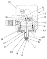
- the drawing shows a nozzle head according to the invention, partly in section.
- the nozzle head 5 shown consists of a housing block 40 to which a nozzle 41 is flanged. This has a nozzle tube 19 which is conically narrowed at its front end and has a front opening 34 and which is integrally formed on a rear flange 42 which is fastened to the housing block 40 by screws.
- a cylinder space 43 provided for the housing block 40 adjoins the bore of the nozzle tube 19. This has a larger diameter than the bore of the nozzle tube 19 and is closed outside by the flange 42.
- an elastic element 18 engaging with a molded cone in the conical narrowing of the nozzle tube 19 is provided, which has a central passage recess 17 which opens out in the area of the front opening 34 of the nozzle tube 19 and with a feed line 16 for which is connected in the form of a jet to a substrate, for example a moving paper web, liquid which can be applied, for example glue or soft liquid.
- a substrate for example a moving paper web
- liquid which can be applied, for example glue or soft liquid.
- the elastic element 18 inserted into the rigidly arranged nozzle tube 19 and supported by the latter is pressed more or less strongly against the associated support surface of the nozzle tube 19 by a pressure pin 20 engaging in the nozzle tube 19.
- the pressure pin 20 is actuated by an actuating device arranged in the housing block 40.
- an adjusting piston 44 is provided in the cylinder chamber 43, from which the pressure pin 20, which has a smaller diameter, projects downwards and which delimits a pressure chamber 45 on the side opposite the pressure pin 20, which pressure pressure, for example compressed air, can be applied to via a supply connection 46 is.
- the pressure of the pressure medium can be adjustable to regulate the pinching of the elastic element 18.
- the maximum actuating movement of the actuating piston 44 is limited by a stop.
- the flange 42 can be provided with a threaded bore in which an adjusting screw 47 is received, which forms an adjustable stop.
- the flange 42 can also be provided with a ventilation recess 48.
- a blind bore 49 extends upwards, into which the feed line 16 for the liquid to be processed opens.
- a sealing pin 50 which is attached to the actuating piston 44 and is opposite the pressure bolt 20, engages in the blind bore 49. This is sealed against the wall of the blind bore 49 by O-rings.
- the actuating piston 44 is sealed off from the wall of the associated cylinder space 43 by O-rings.
- the actuating piston 44 and the pressure bolt 20 and sealing pin 50 attached thereto form a piston arrangement in the form of a stepped piston.
- This entire piston arrangement is provided with a central through bore 51, to which the through recess 17 of the elastic element 18 connects, as a result of which the through recess 17 of the elastic element 18 is connected to the feed line 16.
- the depth of engagement of the sealing pin 50 in the blind bore 49 is greater than the maximum travel of the actuating piston 44, so that the sealing pin 50 in any case remains in engagement with the blind bore 49, as a result of which the pressure chamber 45 remains reliably sealed off from the feed line 16 for the liquid to be processed. This is fed regardless of the position of the actuating piston 44 via the central passage recess 51 to the central passage recess 17 of the elastic element 18.
Landscapes
- Coating Apparatus (AREA)
- Nozzles (AREA)
Abstract
Description
Die Erfindung betrifft eine Vorrichtung zur Erzeugung eines einstellbaren Flüssigkeitsstrahls, insbesondere beim Auftragen von Leim und/oder Soft-Flüssigkeit auf eine Bahn, mit einem Düsenkopf, der eine mit einer am Ende eines mit der zu verarbeitenden Flüssigkeit beaufschlagbaren Strömungswegs angeordneten Öffnung versehene Düse trägt, wobei im Bereich der Öffnung ein elastisches Element vorgesehen ist, das eine mit dem Strömungsweg kommunizierende Durchgangsausnehmung aufweist und das zwischen zwei mittels einer auf dem Düsenhalter vorgesehenen Stelleinrichtung relativ zueinander verstellbaren Preßorganen inform eines vorne verengten, das elastische Element aufnehmenden Düsenrohrs und eines in diese eingreifenden, durchbohrten Druckbolzens angeordnet ist.The invention relates to a device for generating an adjustable jet of liquid, in particular when applying glue and / or soft liquid to a web, with a nozzle head which carries a nozzle provided with an opening arranged at the end of a flow path to which the liquid to be processed can be applied, wherein an elastic element is provided in the area of the opening, which has a passage recess communicating with the flow path and which, between two pressing members which can be adjusted relative to one another by means of an adjusting device provided on the nozzle holder, comprises a nozzle tube which is narrowed at the front and accommodates the elastic element and which engages in this, pierced pressure bolt is arranged.
Eine Anordnung dieser Art ergibt sich aus der EP-A 0 726 095. Hierbei sind das Düsenrohr beweglich und der in dieses eingreifende Druckbolzen starr angeordnet. Es ist daher eine vergleichsweise aufwendige, einen größeren Teilebedarf erfordernde Anordnung zur Betätigung des beweglichen Düsenrohrs erforderlich.An arrangement of this type results from EP-A 0 726 095. Here, the nozzle tube is movable and the pressure pin engaging in it is rigidly arranged. A comparatively complex arrangement, which requires a larger number of parts, is therefore required to actuate the movable nozzle tube.
Hiervon ausgehend ist es daher die Aufgabe der vorliegenden Erfindung, eine Vorrichtung oben erwähnter Art mit einfachen und kostengünstigen Mitteln so zu verbessern, daß eine vergleichsweise einfache Ausbildung der Stelleinrichtung gewährleistet ist.Proceeding from this, it is therefore the object of the present invention to improve a device of the type mentioned above with simple and inexpensive means so that a comparatively simple design of the actuating device is ensured.
Diese Aufgabe wird erfindungsgemäß dadurch gelöst, daß eine mit wenigstens einer mit der Durchgangsausnehmung des elastischen Elements kommunizierenden, durchgehenden Bohrung versehene Kolbenanordnung vorgesehen ist, die den in das Düsenrohr, das am Düsenkopf starr angebracht ist, eingreifenden Druckbolzen, einen hieran anschließenden, auf der vom Druckbolzen abgewandten Seite einen mit einem Druckmittel beaufschlagbaren Druckraum begrenzenden Stellkolben und einen hiervon auf der dem Druckbolzen gegenüberliegenden Seite abstehenden, einen kleineren Durchmesser aufweisenden Dichtzapfen aufweist, der dichtend in eine vom Druckraum abgehende, mit der zu verarbeitenden Flüssigkeit beaufschlagbare Bohrung des Düsenkopfes eingreift.This object is achieved in that a piston is provided with at least one through hole communicating with the passage recess of the elastic element, which engages in the nozzle tube, which is rigidly attached to the nozzle head, the pressure pin, a subsequent one, on which the Side facing away from the pressure pin has an actuating piston that delimits a pressure chamber that can be acted upon by pressure, and has a smaller diameter sealing pin that protrudes from it on the side opposite the pressure pin, which sealingly engages in a bore of the nozzle head that extends from the pressure chamber and can be acted upon with the liquid to be processed.
Diese Maßnahmen ergeben in vorteilhafter Weise einen geringen Teilebedarf und gewährleisten dennoch eine zuverlässige Dichheit des der zu verarbeitenden Flüssigkeit zugeordneten Strömungswegs. Hierdurch werden daher eine kostengünstige Herstellung sowie eine hohe Wartungsfreundlichkeit gewährleistet.These measures advantageously result in a low parts requirement and nevertheless ensure reliable tightness of the flow path assigned to the liquid to be processed. As a result, cost-effective production and ease of maintenance are guaranteed.
Vorteilhafte Ausgestaltungen und zweckmäßige Fortbildungen der übergeordneten Maßnahmen sind in den Unteransprüchen angegeben und aus der nachstehenden Beispielsbeschreibung anhand der Zeichnung entnehmbar.Advantageous refinements and expedient further training of the higher-level measures are specified in the subclaims and can be found in the following description of the examples with reference to the drawing.
Die Zeichnung zeigt einen erfindungsgemäßen Düsenkopf teilweise im Schnitt.The drawing shows a nozzle head according to the invention, partly in section.
Der grundsätzliche Aufbau und die grundsätzliche Wirkungsweise der vorliegenden Anordnung entsprechen der Anordnung gemäß EP-A 0 726 095, worauf zur Vermeidung von Wiederholungen Bezug genommen wird. In der nachstehenden Beschreibung werden daher in erster Linie die Unterschiede behandelt, wobei für gleiche Teile gleiche Bezugszeichen Verwendung finden.The basic structure and the basic mode of operation of the present arrangement correspond to the arrangement according to EP-A 0 726 095, to which reference is made to avoid repetitions. In the following description, the differences are primarily dealt with, the same reference numerals being used for the same parts.
Der dargestellte Düsenkopf 5 besteht aus einem Gehäuseblock 40, an den eine Düse 41 angeflanscht ist. Diese besitzt ein an ihrem vorderen Ende konisch verengtes, eine vordere Öffnung 34 aufweisendes Düsenrohr 19, das an einen rückwärtigen Flansch 42 angeformt ist, der durch Schrauben am Gehäuseblock 40 befestigt ist.The nozzle head 5 shown consists of a
An die Bohrung des Düsenrohrs 19 schließt sich ein dem Gehäuseblock 40 vorgesehener Zylinderraum 43 an. Dieser besitzt einen größeren Durchmesser als die Bohrung des Düsenrohrs 19 und ist außerhalb dieses durch den Flansch 42 verschlossen.A
Im vorderen Bereich des Düsenrohrs 19 ist ein mit einem angeformten Konus in die konische Verengung des Düsenrohrs 19 eingreifendes, elastisches Element 18 vorgesehen, das eine zentrale Durchgangsausnehmung 17 aufweist, die im Bereich der vorderen Öffnung 34 des Düsenrohrs 19 ausmündet und mit einer Zuleitung 16 für die in Form eines Strahls auf ein Substrat, beispielsweise eine bewegte Papierbahn, aufbringbare Flüssigkeit, beispielsweise Leim oder Soft-Flüssigkeit, verbunden ist. Zur Einstellung des Strahldurchmessers und damit des Mengendurchsatzes wird das elastische Element 18 mehr oder weniger gequetscht, wodurch sich die lichte Weite seiner Durchgangsausnehmung 17 verändert.In the front area of the
Hierzu wird das in das starr angeordnete Düsenrohr 19 eingelegte und von diesem abgestützte elastische Element 18 durch einen in das Düsenrohr 19 eingreifenden Druckbolzen 20 mehr oder weniger stark an die zugeordnete Stützfläche des Düsenrohrs 19 angepreßt.For this purpose, the elastic element 18 inserted into the rigidly arranged
Der Druckbolzen 20 wird durch eine im Gehäuseblock 40 angeordnete Stelleinrichtung betätigt.The
Hierzu ist ein im Zylinderraum 43 angeordneter Stellkolben 44 vorgesehen, von dem der einen Kleineren Durchmesser aufweisende Druckbolzen 20 nach unten absteht und der auf der dem Druckbolzen 20 gegegenüberliegenden Seite einen Druckraum 45 begrenzt, der über einen Versorgungsanschluß 46 mit einem Druckmittel, beispielsweise Preßluft, beaufschlagbar ist. Der Druck des Druckmittels kann zur Regulierung der Quetschung des elastischen Elements 18 einstellbar sein. Die maximale Stellbewegung des Stellkolbens 44 wird durch einen Anschlag begrenzt. Hierzu kann der Flansch 42 mit einer Gewindebohrung versehen sein, in der eine Stellschraube 47 aufgenommen ist, die einen einstellbaren Anschlag bildet. Der Flansch 42 kann auch mit einer Entlüftungsausnehmung 48 versehen sein.For this purpose, an adjusting piston 44 is provided in the
Von dem durch den oberen Bereich des Zylinderraums 43 gebildeten Druckraum 45 geht eine Sackbohrung 49 nach oben ab, in die die Zuleitung 16 für die zu verarbeitende Flüssigkeit mündet. In die Sackbohrung 49 greift ein an den Stellkolben 44 angesetzter, dem Druckbolzen 20 gegenüberliegender Dichtzapfen 50 ein. Dieser ist durch O-Ringe gegenüber der Wand der Sackbohrung 49 abgedichtet. Ebenso ist der Stellkolben 44 durch O-Ringe gegenüber der Wand des zugeordneten Zylinderraums 43 abgedichtet.From the
Der Stellkolben 44 sowie der hieran angesetzte Druckbolzen 20 und Dichtzapfen 50 bilden eine Kolbenanordnung in Form eines Stufenkolbens. Diese gesamte Kolbenanordnung ist mit einer zentralen Durchgangsbohrung 51 versehen, an die die Durchgangsausnehmung 17 des elastischen Elements 18 anschließt, wodurch die Durchgangsausnehmung 17 des elastischen Elements 18 mit der Zuleitung 16 verbunden ist. Die Eingriffstiefe des Dichtzapfens 50 in die Sackbohrung 49 ist größer als der maximale Stellweg des Stellkolbens 44, so daß der Dichtzapfen 50 in jedem Fall im Eingriff mit der Sackbohrung 49 bleibt, wodurch der Druckraum 45 zuverlässig gegenüber der Zuleitung 16 für die zu verarbeitende Flüssigkeit abgedichtet bleibt. Diese wird unabhängig von der Stellung des Stellkolbens 44 über die zentrale Durchgangsausnehmung 51 der zentralen Durchgangsausnehmung 17 des elastischen Elements 18 zugeführt.The actuating piston 44 and the
Claims (4)
Applications Claiming Priority (2)
| Application Number | Priority Date | Filing Date | Title |
|---|---|---|---|
| DE19617479A DE19617479A1 (en) | 1995-02-13 | 1996-05-02 | Device for generating adjustable fluid jet, especially for application of adhesive |
| DE19617479 | 1996-05-02 |
Publications (3)
| Publication Number | Publication Date |
|---|---|
| EP0804968A2 true EP0804968A2 (en) | 1997-11-05 |
| EP0804968A3 EP0804968A3 (en) | 1998-08-19 |
| EP0804968B1 EP0804968B1 (en) | 2002-10-02 |
Family
ID=7793017
Family Applications (1)
| Application Number | Title | Priority Date | Filing Date |
|---|---|---|---|
| EP97106508A Expired - Lifetime EP0804968B1 (en) | 1996-05-02 | 1997-04-19 | Device for producing an adjustable fluid jet |
Country Status (4)
| Country | Link |
|---|---|
| US (1) | US5850974A (en) |
| EP (1) | EP0804968B1 (en) |
| JP (1) | JPH1034031A (en) |
| DE (1) | DE59708349D1 (en) |
Families Citing this family (5)
| Publication number | Priority date | Publication date | Assignee | Title |
|---|---|---|---|---|
| DE19849687A1 (en) * | 1998-10-28 | 2000-05-04 | Valeo Auto Electric Gmbh | Nozzle element for a windscreen washer system of a vehicle |
| US6250572B1 (en) * | 2000-09-07 | 2001-06-26 | Globe Union Industrial Corp. | Showerhead |
| JP5109850B2 (en) | 2008-07-16 | 2012-12-26 | セイコーエプソン株式会社 | Image carrier cleaning device, cleaning method, and image forming apparatus |
| CN117142752B (en) * | 2023-08-31 | 2024-02-27 | 佛山科学技术学院 | A nozzle adjustment mechanism for a gas jet nozzle |
| US20250121396A1 (en) * | 2023-10-17 | 2025-04-17 | Raven Industries, Inc. | Multifunctional nozzle assembly for agricultural vehicles |
Family Cites Families (8)
| Publication number | Priority date | Publication date | Assignee | Title |
|---|---|---|---|---|
| DE708961C (en) * | 1936-10-21 | 1941-08-01 | Hans Metz | Jet pipe for fire extinguishing purposes |
| US2793080A (en) * | 1949-03-19 | 1957-05-21 | Warren G Brown | Nozzle for spraying cementitious materials |
| US3291396A (en) * | 1964-11-30 | 1966-12-13 | Walter John | Self-purging mixing and spraying apparatus |
| US3550861A (en) * | 1968-08-28 | 1970-12-29 | William R Teson | Hose nozzle |
| US3711020A (en) * | 1970-07-06 | 1973-01-16 | R Zelna | High frequency solder paste gun |
| SU1057689A1 (en) * | 1982-06-10 | 1983-11-30 | Всесоюзный научно-исследовательский институт золота и редких металлов | Hydraulic monitor nozzle |
| JP2532323Y2 (en) * | 1990-10-26 | 1997-04-16 | 株式会社いけうち | nozzle |
| FR2687333A1 (en) * | 1992-02-14 | 1993-08-20 | Tecnoma | LIQUID SPRAY NOZZLE. |
-
1997
- 1997-04-10 JP JP9092332A patent/JPH1034031A/en active Pending
- 1997-04-14 US US08/843,284 patent/US5850974A/en not_active Expired - Fee Related
- 1997-04-19 EP EP97106508A patent/EP0804968B1/en not_active Expired - Lifetime
- 1997-04-19 DE DE59708349T patent/DE59708349D1/en not_active Expired - Lifetime
Also Published As
| Publication number | Publication date |
|---|---|
| EP0804968B1 (en) | 2002-10-02 |
| DE59708349D1 (en) | 2002-11-07 |
| US5850974A (en) | 1998-12-22 |
| JPH1034031A (en) | 1998-02-10 |
| EP0804968A3 (en) | 1998-08-19 |
Similar Documents
| Publication | Publication Date | Title |
|---|---|---|
| DE69715936T2 (en) | Hot glue applicator and nozzle therefor | |
| DE3246738C2 (en) | Self-medium controlled hydraulic valve with adjustable flow cross-section | |
| DE2032361C3 (en) | Two-stage servo control valve | |
| EP0236464B1 (en) | Riveting tool | |
| DE69108492T2 (en) | Back pressure control valve. | |
| DE102018133606B3 (en) | Jet metering valve | |
| DE69720847T2 (en) | Fastener driving tool with a valve for entire cycles | |
| EP1038592B1 (en) | Device for dosing and delivering flowing fluids | |
| DE3123740A1 (en) | OIL PRESSURE CONTROL VALVE | |
| DE19617479A1 (en) | Device for generating adjustable fluid jet, especially for application of adhesive | |
| EP0804968B1 (en) | Device for producing an adjustable fluid jet | |
| DE10046326B4 (en) | Device for applying fluid, in particular hotmelt adhesive, to a substrate which can be moved relative to the device | |
| DE4031885A1 (en) | Magnetic flow valve - has two position armature and spring which can be reversed in conjunction with end spacer affording normally closed and open alternatives | |
| DE19622948C2 (en) | Manually operated hydraulic pilot control device | |
| DE4135277C2 (en) | Control device for an adjustable hydraulic pump | |
| DE3710830C2 (en) | ||
| DE4432027A1 (en) | Hydraulic pressure control device for a servo system of an automatic transmission | |
| DE9316085U1 (en) | Application head for applying cold glue to a substrate | |
| EP0662565B1 (en) | Hydraulic amplifier | |
| DD252418A5 (en) | HIGH PRESSURE RELAXATION VALVE | |
| CH658703A5 (en) | SOLENOID VALVE UNIT. | |
| DE2435877C2 (en) | Control valve | |
| DE102011118343A1 (en) | Valve i.e. proportional pressure regulating valve, for controlling pressurized air, has valve seat pairs differently formed such that collar of one seat pair is pressed on sealing element in depth larger than depth of another seat pair | |
| DE10311754B4 (en) | Paint pressure control means | |
| DE19649920A1 (en) | Start valve |
Legal Events
| Date | Code | Title | Description |
|---|---|---|---|
| PUAI | Public reference made under article 153(3) epc to a published international application that has entered the european phase |
Free format text: ORIGINAL CODE: 0009012 |
|
| AK | Designated contracting states |
Kind code of ref document: A2 Designated state(s): BE CH DE ES FR GB IT LI NL SE |
|
| PUAL | Search report despatched |
Free format text: ORIGINAL CODE: 0009013 |
|
| AK | Designated contracting states |
Kind code of ref document: A3 Designated state(s): BE CH DE ES FR GB IT LI NL SE |
|
| 17P | Request for examination filed |
Effective date: 19981009 |
|
| 17Q | First examination report despatched |
Effective date: 19990510 |
|
| GRAG | Despatch of communication of intention to grant |
Free format text: ORIGINAL CODE: EPIDOS AGRA |
|
| GRAG | Despatch of communication of intention to grant |
Free format text: ORIGINAL CODE: EPIDOS AGRA |
|
| GRAH | Despatch of communication of intention to grant a patent |
Free format text: ORIGINAL CODE: EPIDOS IGRA |
|
| RAP1 | Party data changed (applicant data changed or rights of an application transferred) |
Owner name: BALDWIN GERMANY GMBH |
|
| GRAH | Despatch of communication of intention to grant a patent |
Free format text: ORIGINAL CODE: EPIDOS IGRA |
|
| GRAA | (expected) grant |
Free format text: ORIGINAL CODE: 0009210 |
|
| AK | Designated contracting states |
Kind code of ref document: B1 Designated state(s): BE CH DE ES FR GB IT LI NL SE |
|
| PG25 | Lapsed in a contracting state [announced via postgrant information from national office to epo] |
Ref country code: NL Free format text: LAPSE BECAUSE OF FAILURE TO SUBMIT A TRANSLATION OF THE DESCRIPTION OR TO PAY THE FEE WITHIN THE PRESCRIBED TIME-LIMIT Effective date: 20021002 Ref country code: IT Free format text: LAPSE BECAUSE OF FAILURE TO SUBMIT A TRANSLATION OF THE DESCRIPTION OR TO PAY THE FEE WITHIN THE PRESCRIBED TIME-LIMIT;WARNING: LAPSES OF ITALIAN PATENTS WITH EFFECTIVE DATE BEFORE 2007 MAY HAVE OCCURRED AT ANY TIME BEFORE 2007. THE CORRECT EFFECTIVE DATE MAY BE DIFFERENT FROM THE ONE RECORDED. Effective date: 20021002 Ref country code: GB Free format text: LAPSE BECAUSE OF FAILURE TO SUBMIT A TRANSLATION OF THE DESCRIPTION OR TO PAY THE FEE WITHIN THE PRESCRIBED TIME-LIMIT Effective date: 20021002 Ref country code: FR Free format text: LAPSE BECAUSE OF FAILURE TO SUBMIT A TRANSLATION OF THE DESCRIPTION OR TO PAY THE FEE WITHIN THE PRESCRIBED TIME-LIMIT Effective date: 20021002 |
|
| REG | Reference to a national code |
Ref country code: GB Ref legal event code: FG4D Free format text: NOT ENGLISH |
|
| REG | Reference to a national code |
Ref country code: CH Ref legal event code: EP |
|
| REF | Corresponds to: |
Ref document number: 59708349 Country of ref document: DE Date of ref document: 20021107 |
|
| PG25 | Lapsed in a contracting state [announced via postgrant information from national office to epo] |
Ref country code: SE Free format text: LAPSE BECAUSE OF FAILURE TO SUBMIT A TRANSLATION OF THE DESCRIPTION OR TO PAY THE FEE WITHIN THE PRESCRIBED TIME-LIMIT Effective date: 20030102 |
|
| NLV1 | Nl: lapsed or annulled due to failure to fulfill the requirements of art. 29p and 29m of the patents act | ||
| GBV | Gb: ep patent (uk) treated as always having been void in accordance with gb section 77(7)/1977 [no translation filed] |
Effective date: 20021002 |
|
| PG25 | Lapsed in a contracting state [announced via postgrant information from national office to epo] |
Ref country code: ES Free format text: LAPSE BECAUSE OF FAILURE TO SUBMIT A TRANSLATION OF THE DESCRIPTION OR TO PAY THE FEE WITHIN THE PRESCRIBED TIME-LIMIT Effective date: 20030429 |
|
| PG25 | Lapsed in a contracting state [announced via postgrant information from national office to epo] |
Ref country code: LI Free format text: LAPSE BECAUSE OF NON-PAYMENT OF DUE FEES Effective date: 20030430 Ref country code: CH Free format text: LAPSE BECAUSE OF NON-PAYMENT OF DUE FEES Effective date: 20030430 Ref country code: BE Free format text: LAPSE BECAUSE OF NON-PAYMENT OF DUE FEES Effective date: 20030430 |
|
| EN | Fr: translation not filed | ||
| PLBE | No opposition filed within time limit |
Free format text: ORIGINAL CODE: 0009261 |
|
| STAA | Information on the status of an ep patent application or granted ep patent |
Free format text: STATUS: NO OPPOSITION FILED WITHIN TIME LIMIT |
|
| 26N | No opposition filed |
Effective date: 20030703 |
|
| BERE | Be: lapsed |
Owner name: *BALDWIN GERMANY G.M.B.H. Effective date: 20030430 |
|
| REG | Reference to a national code |
Ref country code: CH Ref legal event code: PL |
|
| PGFP | Annual fee paid to national office [announced via postgrant information from national office to epo] |
Ref country code: DE Payment date: 20110504 Year of fee payment: 15 |
|
| REG | Reference to a national code |
Ref country code: DE Ref legal event code: R119 Ref document number: 59708349 Country of ref document: DE Effective date: 20121101 |
|
| PG25 | Lapsed in a contracting state [announced via postgrant information from national office to epo] |
Ref country code: DE Free format text: LAPSE BECAUSE OF NON-PAYMENT OF DUE FEES Effective date: 20121101 |