EP0804987A2 - Support pour une paire de couteau circulaire - Google Patents
Support pour une paire de couteau circulaire Download PDFInfo
- Publication number
- EP0804987A2 EP0804987A2 EP97105587A EP97105587A EP0804987A2 EP 0804987 A2 EP0804987 A2 EP 0804987A2 EP 97105587 A EP97105587 A EP 97105587A EP 97105587 A EP97105587 A EP 97105587A EP 0804987 A2 EP0804987 A2 EP 0804987A2
- Authority
- EP
- European Patent Office
- Prior art keywords
- axis
- knife
- frame
- knife holder
- holder according
- Prior art date
- Legal status (The legal status is an assumption and is not a legal conclusion. Google has not performed a legal analysis and makes no representation as to the accuracy of the status listed.)
- Granted
Links
Images

Classifications
-
- B—PERFORMING OPERATIONS; TRANSPORTING
- B26—HAND CUTTING TOOLS; CUTTING; SEVERING
- B26D—CUTTING; DETAILS COMMON TO MACHINES FOR PERFORATING, PUNCHING, CUTTING-OUT, STAMPING-OUT OR SEVERING
- B26D1/00—Cutting through work characterised by the nature or movement of the cutting member or particular materials not otherwise provided for; Apparatus or machines therefor; Cutting members therefor
- B26D1/01—Cutting through work characterised by the nature or movement of the cutting member or particular materials not otherwise provided for; Apparatus or machines therefor; Cutting members therefor involving a cutting member which does not travel with the work
- B26D1/12—Cutting through work characterised by the nature or movement of the cutting member or particular materials not otherwise provided for; Apparatus or machines therefor; Cutting members therefor involving a cutting member which does not travel with the work having a cutting member moving about an axis
- B26D1/14—Cutting through work characterised by the nature or movement of the cutting member or particular materials not otherwise provided for; Apparatus or machines therefor; Cutting members therefor involving a cutting member which does not travel with the work having a cutting member moving about an axis with a circular cutting member, e.g. disc cutter
- B26D1/24—Cutting through work characterised by the nature or movement of the cutting member or particular materials not otherwise provided for; Apparatus or machines therefor; Cutting members therefor involving a cutting member which does not travel with the work having a cutting member moving about an axis with a circular cutting member, e.g. disc cutter coacting with another disc cutter
- B26D1/245—Cutting through work characterised by the nature or movement of the cutting member or particular materials not otherwise provided for; Apparatus or machines therefor; Cutting members therefor involving a cutting member which does not travel with the work having a cutting member moving about an axis with a circular cutting member, e.g. disc cutter coacting with another disc cutter for thin material, e.g. for sheets, strips or the like
-
- B—PERFORMING OPERATIONS; TRANSPORTING
- B23—MACHINE TOOLS; METAL-WORKING NOT OTHERWISE PROVIDED FOR
- B23D—PLANING; SLOTTING; SHEARING; BROACHING; SAWING; FILING; SCRAPING; LIKE OPERATIONS FOR WORKING METAL BY REMOVING MATERIAL, NOT OTHERWISE PROVIDED FOR
- B23D19/00—Shearing machines or shearing devices cutting by rotary discs
- B23D19/04—Shearing machines or shearing devices cutting by rotary discs having rotary shearing discs arranged in co-operating pairs
- B23D19/06—Shearing machines or shearing devices cutting by rotary discs having rotary shearing discs arranged in co-operating pairs with several spaced pairs of shearing discs working simultaneously, e.g. for trimming or making strips
-
- B—PERFORMING OPERATIONS; TRANSPORTING
- B26—HAND CUTTING TOOLS; CUTTING; SEVERING
- B26D—CUTTING; DETAILS COMMON TO MACHINES FOR PERFORATING, PUNCHING, CUTTING-OUT, STAMPING-OUT OR SEVERING
- B26D7/00—Details of apparatus for cutting, cutting-out, stamping-out, punching, perforating, or severing by means other than cutting
- B26D7/26—Means for mounting or adjusting the cutting member; Means for adjusting the stroke of the cutting member
- B26D7/2628—Means for adjusting the position of the cutting member
- B26D7/2635—Means for adjusting the position of the cutting member for circular cutters
-
- Y—GENERAL TAGGING OF NEW TECHNOLOGICAL DEVELOPMENTS; GENERAL TAGGING OF CROSS-SECTIONAL TECHNOLOGIES SPANNING OVER SEVERAL SECTIONS OF THE IPC; TECHNICAL SUBJECTS COVERED BY FORMER USPC CROSS-REFERENCE ART COLLECTIONS [XRACs] AND DIGESTS
- Y10—TECHNICAL SUBJECTS COVERED BY FORMER USPC
- Y10T—TECHNICAL SUBJECTS COVERED BY FORMER US CLASSIFICATION
- Y10T83/00—Cutting
- Y10T83/768—Rotatable disc tool pair or tool and carrier
- Y10T83/7809—Tool pair comprises rotatable tools
- Y10T83/783—Tool pair comprises contacting overlapped discs
- Y10T83/7834—With means to effect axial pressure on pair
-
- Y—GENERAL TAGGING OF NEW TECHNOLOGICAL DEVELOPMENTS; GENERAL TAGGING OF CROSS-SECTIONAL TECHNOLOGIES SPANNING OVER SEVERAL SECTIONS OF THE IPC; TECHNICAL SUBJECTS COVERED BY FORMER USPC CROSS-REFERENCE ART COLLECTIONS [XRACs] AND DIGESTS
- Y10—TECHNICAL SUBJECTS COVERED BY FORMER USPC
- Y10T—TECHNICAL SUBJECTS COVERED BY FORMER US CLASSIFICATION
- Y10T83/00—Cutting
- Y10T83/768—Rotatable disc tool pair or tool and carrier
- Y10T83/7809—Tool pair comprises rotatable tools
- Y10T83/783—Tool pair comprises contacting overlapped discs
- Y10T83/7843—With means to change overlap of discs
-
- Y—GENERAL TAGGING OF NEW TECHNOLOGICAL DEVELOPMENTS; GENERAL TAGGING OF CROSS-SECTIONAL TECHNOLOGIES SPANNING OVER SEVERAL SECTIONS OF THE IPC; TECHNICAL SUBJECTS COVERED BY FORMER USPC CROSS-REFERENCE ART COLLECTIONS [XRACs] AND DIGESTS
- Y10—TECHNICAL SUBJECTS COVERED BY FORMER USPC
- Y10T—TECHNICAL SUBJECTS COVERED BY FORMER US CLASSIFICATION
- Y10T83/00—Cutting
- Y10T83/768—Rotatable disc tool pair or tool and carrier
- Y10T83/7809—Tool pair comprises rotatable tools
- Y10T83/7847—Tool element axially shiftable
-
- Y—GENERAL TAGGING OF NEW TECHNOLOGICAL DEVELOPMENTS; GENERAL TAGGING OF CROSS-SECTIONAL TECHNOLOGIES SPANNING OVER SEVERAL SECTIONS OF THE IPC; TECHNICAL SUBJECTS COVERED BY FORMER USPC CROSS-REFERENCE ART COLLECTIONS [XRACs] AND DIGESTS
- Y10—TECHNICAL SUBJECTS COVERED BY FORMER USPC
- Y10T—TECHNICAL SUBJECTS COVERED BY FORMER US CLASSIFICATION
- Y10T83/00—Cutting
- Y10T83/929—Tool or tool with support
- Y10T83/9457—Joint or connection
- Y10T83/9464—For rotary tool
- Y10T83/9469—Adjustable
- Y10T83/9471—Rectilinearly
Definitions
- the circular knives are either arranged on two knife shafts (see e.g. DE 40 05 271 C1) or in pairs on individually movable brackets (see e.g. WO 94/00261).
- the present invention relates to an arrangement of the latter type with a frame which is longitudinally displaceable on guide rails and has an upper and a lower part for the separate storage of one circular knife each, a cutting plane being provided by the cutting edges assigned to one another.
- the two circular knives in a pair have a cutting gap.
- the term cutting plane has been used here neglecting the cutting gap.
- the knife holder known from WO 94/00261 has a large number of individual parts (central knife shaft, centering piece for the transport ring and circular knife, two roller bearings, a sliding sleeve with thread, slotted nut, holder for the sliding sleeve carried through the frame). If you add a certain tolerance to each individual part, the addition of the individual tolerances can result in a considerable deviation or vice versa: If a certain tolerance is prescribed for the circular knives, the individual parts must have a very low tolerance, which requires a high manufacturing effort power.
- the round knives of the known holder are supported on a part of the shaft that is located outside of the bearing, which results in a large collar length, which leads to a risk of tipping and thus impairs the cutting result. To disassemble the knives, a centering piece must first be removed due to the overlap of the knives, which additionally increases the effort when assembling or disassembling.
- the invention has for its object to reduce the required number of parts of the knife holder, to increase the safety against tipping and to reduce the effort for production and assembly.
- each knife is supported by a pivot bearing on an axis pivotally and fixably held in a recess of the frame, that the cutting plane penetrates each of the pivot bearings and that the axis of rotation of the axis of the pivot bearing relative to the axis of rotation of the held in the frame Part of the axis has an eccentricity.
- An axle that can be held in a frame has a high load capacity. If the cutting plane penetrates the rotary bearings, this means that the rotary bearings are arranged in the region of the action of force and thus the risk of the round knives tipping over is prevented. Due to the intended eccentricity of the rotary bearing relative to the part of the axis located in the frame, it is possible in a simple manner by pivoting the axis to pivot the circular knives out of the area of the overlap and to disassemble them.
- the axis is drawn into the recess of the frame via a cover plate and fixed.
- the cover plate is secured against twisting both against the axis and against the frame.
- the cover plate can be secured against rotation with respect to the frame by a spring-loaded latching device and with respect to the axis by centering pins.
- a further development of the invention provides for a spring arrangement to be provided between the pivot bearing and the frame and to combine the ascertainability of the axis with an axial adjustability, the axial adjustability in a preferred embodiment being determined by the axial dimension between a central contact surface of the cover plate provided for contact with the axis and one for contact with the frame.
- a particularly compact design of the knife bearing arrangement results if the rotary bearing is formed directly by a part of the axis held in the frame and / or a ring carrying the circular knife. With a counter knife diameter, the axis and the bearing can be dimensioned large, which results in a high load capacity and service life of the parts.
- the circular knife is attached to a flange of the bearing ring, whereby it can be quickly brought into position by a centering shoulder.
- the transport ring has to be changed more frequently in operation than the circular knife.
- additional fastening means are also provided.
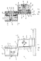
- the holder 1 shows a side view of one of a plurality of circular knife holders 1 which are longitudinally displaceable and fixable on a guide rail arrangement.
- the holder 1 has an upper, approximately S-shaped frame 2, which is fastened on a slide 3, which in turn is slidably guided on guide rails 4.
- annular circular knife M1 also referred to as a ring knife
- a second circular knife M2 is mounted on the right side
- Circular knives M1, M2 lie essentially in the same plane, the cutting plane S.
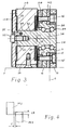
- peg-shaped bearing axes 5a, 5b are provided, which are inserted with a first part 5c and 5d in corresponding recesses 6a, 6b of the frame parts 2a and 2b and - seen in the axial direction - on the other frame part 2b or 2a protrude.
- the bearing axles 5a, 5b are each formed on their part 7a, 7b protruding from the respective frame part 2a or 2b as an inner part of a roller bearing 8a, 8b.
- the central axis of the roller bearing parts 7a, 7b and the axis of rotation of the peg-shaped bearing axis parts 5c and 5d have an eccentricity E1 and E2 to one another.
- the bearing axes 5a, 5b are rotatably or pivotably mounted in the recesses 6a, 6b of the frame parts 2a, 2b, so that the central or rotational axis of the roller bearing parts 7a, 7b - seen in the end view - with respect to the axis of rotation of the bearing axis 5a, 5b can be brought up, down, to the right, to the left and in all intermediate positions.
- roller bearings 8a, 8b each have an outer support or bearing ring 9a or 9b with a flange 10.
- a front or rear circumferential recess with an associated centering shoulder 11 or 12 is arranged on both sides of the flange 10.
- the recess with the centering shoulder 11 facing away from the bearing axles 5a or 5b accommodates the circular knife M1 or M2, which bears against the flange 10, and a support ring 15 provided with a transport ring 14 made of elastic material.
- the circular knives M1, M2 are fastened by means of screws 16 which engage with their threads in corresponding threads of a retaining ring 17a or 17b arranged in the recess with the centering shoulder 12. Additional screws 16 'are provided for fastening the support ring 15.
- the lower retaining ring 17a is provided with external teeth 18 and is in engagement with a drive wheel, not shown.
- a circumferential flange 19 is arranged between the two bearing axis parts 5c, 7a and 5d, 7b of the bearing axes 5a, 5b.
- the flange serves directly as a contact with the lower frame part 2a.
- a spring ring 20 is arranged between the flange 19 and the upper frame part 2b, which holds the bearing axis 5b and with it the circular knife M2 axially in the direction of the lower knife arrangement under prestress.
- the bearing axles 5a, 5b are drawn into the recesses 6a, 6b by means of cover plates 21a, 21b lying on the outside of the frame parts 2a, 2b and held there. This results in the lower one Knife storage through the contact of the flange 19 on the frame part 2a a clear axial position.
- the upper cover plate 21b rests with a central contact surface 23 on the end face of the bearing axis 5b and, viewed radially, with the outer contact surface 24 against the upper frame part 2b.
- the cover plate 21b is non-rotatably connected to the bearing axis 5b by pins 25. By rotating the cover plate 21b, the bearing axis 5b can be rotated accordingly and thus the position of the eccentricity E2 can be changed.
- a radial overlap LR is generally set (cf. 4), ie when looking in the axial direction, the circumferential lines of the two circular knives M1, M2 overlap.
- At least one axis 5a or 5b is pivoted such that the eccentricity of the axis parts 7a or 7b points away from the other knife bearing and an overlap of the circular knives M1 and M2 is eliminated.
- the transport ring 14 alone or together with the relevant circular knife on the support ring 9a or 9b or the entire knife bearing including the bearing axis 5a or 5b can be replaced.
- the wear plates 26 shown in FIGS. 2 and 3 prevent the frame 2 from wearing.
- FIG. 5 shows a spring-loaded ball 27 which, like the spring 28 which loads it, is located in a recess 29 in the upper frame part 2b.
- the cover plate 21b has two or more small recesses 30 at corresponding points for partial penetration or engagement of the ball 27.
- the bottom and top can The position of the eccentricity E2 and any intermediate positions when the ball 27 snaps into the recess 30 can be easily found.
Landscapes
- Engineering & Computer Science (AREA)
- Mechanical Engineering (AREA)
- Life Sciences & Earth Sciences (AREA)
- Forests & Forestry (AREA)
- Details Of Cutting Devices (AREA)
- Harvester Elements (AREA)
- Threshing Machine Elements (AREA)
- Nonmetal Cutting Devices (AREA)
- Spinning Or Twisting Of Yarns (AREA)
- Shearing Machines (AREA)
- Removal Of Insulation Or Armoring From Wires Or Cables (AREA)
- Food-Manufacturing Devices (AREA)
- Polishing Bodies And Polishing Tools (AREA)
- Gripping Jigs, Holding Jigs, And Positioning Jigs (AREA)
- Toys (AREA)
- Details Of Rigid Or Semi-Rigid Containers (AREA)
- Rolls And Other Rotary Bodies (AREA)
Applications Claiming Priority (2)
| Application Number | Priority Date | Filing Date | Title |
|---|---|---|---|
| DE19617713 | 1996-05-03 | ||
| DE19617713A DE19617713A1 (de) | 1996-05-03 | 1996-05-03 | Halterung für Rundmesserpaar |
Publications (3)
| Publication Number | Publication Date |
|---|---|
| EP0804987A2 true EP0804987A2 (fr) | 1997-11-05 |
| EP0804987A3 EP0804987A3 (fr) | 1998-08-19 |
| EP0804987B1 EP0804987B1 (fr) | 2002-10-30 |
Family
ID=7793187
Family Applications (1)
| Application Number | Title | Priority Date | Filing Date |
|---|---|---|---|
| EP97105587A Expired - Lifetime EP0804987B1 (fr) | 1996-05-03 | 1997-04-04 | Support pour une paire de couteau circulaire |
Country Status (9)
| Country | Link |
|---|---|
| US (1) | US5865083A (fr) |
| EP (1) | EP0804987B1 (fr) |
| CN (1) | CN1167023A (fr) |
| AT (1) | ATE226862T1 (fr) |
| BR (1) | BR9701984A (fr) |
| DE (2) | DE19617713A1 (fr) |
| ES (1) | ES2181942T3 (fr) |
| PT (1) | PT804987E (fr) |
| TW (1) | TW368443B (fr) |
Families Citing this family (8)
| Publication number | Priority date | Publication date | Assignee | Title |
|---|---|---|---|---|
| US6308601B1 (en) * | 1998-11-19 | 2001-10-30 | Eastman Kodak Company | Apparatus and method for slitting a sheet of web material |
| US6874398B2 (en) * | 2002-10-18 | 2005-04-05 | Spiro Sa | Assembly for cutting a tube |
| US20100258017A1 (en) * | 2009-04-10 | 2010-10-14 | Kersey Kevin T | Print Media Slitter |
| TWI370051B (en) * | 2009-05-15 | 2012-08-11 | Primax Electronics Ltd | Paper cutting mechanism |
| CN103240457B (zh) * | 2011-12-31 | 2015-03-25 | 新华都特种电气股份有限公司 | 一种用于开料机的机头及开料机 |
| CH708130A1 (de) * | 2013-05-31 | 2014-12-15 | Can Man Ag | Schere zum Anfertigen von Blechzuschnitten aus Blechtafeln oder Blechbändern. |
| CN103990850B (zh) * | 2014-05-26 | 2016-08-17 | 东莞市晋诚机械有限公司 | 一种自动高速金属管材裁断机 |
| CN105344816B (zh) * | 2015-11-20 | 2018-02-02 | 无锡国誉精密机械有限公司 | 空调翅片模具 |
Family Cites Families (15)
| Publication number | Priority date | Publication date | Assignee | Title |
|---|---|---|---|---|
| US3908499A (en) * | 1973-08-01 | 1975-09-30 | William Dale Reed | Knife retainer |
| US4220064A (en) * | 1979-02-21 | 1980-09-02 | Paxson Machine Company | Clamping device |
| US4245534A (en) * | 1979-08-02 | 1981-01-20 | Van Mark Products Corporation | Slitter for sheet metal or the like |
| US4280386A (en) * | 1979-12-26 | 1981-07-28 | The Ward Machinery Company | Paperboard slitting apparatus |
| US4380945A (en) * | 1981-01-26 | 1983-04-26 | Beloit Corporation | Preadjustable web slitter and non-deflecting mounting therefor |
| AT381662B (de) * | 1982-08-16 | 1986-11-10 | Mogilevskij Otdel Fiz T I | Rotationsmeissel und halterung zu dessen befestigung im meisselhalter |
| US5025693A (en) * | 1989-01-03 | 1991-06-25 | Tidland Corporation, A Washington Corp. | Side shifting apparatus for cutting blade in a web slitting machine |
| US4962684A (en) * | 1989-04-07 | 1990-10-16 | Mowry Donald E | Cutting device for a board machine |
| US5007318A (en) * | 1989-12-20 | 1991-04-16 | National Steel Corporation | Metal strip edge trimming apparatus |
| DE4034252A1 (de) * | 1990-10-27 | 1992-04-30 | Goebel Gmbh Maschf | Unterstuetzungseinrichtung |
| EP0569767B1 (fr) * | 1992-05-13 | 1996-01-03 | SCHOBER GmbH Werkzeug- und Maschinenbau | Support de couteau |
| CH685687A5 (de) * | 1992-06-25 | 1995-09-15 | Mawag Maschinenbau Ag | Rollschneideinheit. |
| DE4308044C1 (de) * | 1993-03-13 | 1994-10-06 | Roland Man Druckmasch | Längsschneideinrichtung für Bahnen |
| DE4405399C2 (de) * | 1994-02-21 | 1996-02-29 | Sundwiger Eisen Maschinen | Besäumschere für Bänder, insbesondere aus Metall |
| FR2732638B1 (fr) * | 1995-04-10 | 1997-05-09 | Kodak Pathe | Module de coupe pour produit en bande et dispositif de coupe equipe d'au moins un tel module |
-
1996
- 1996-05-03 DE DE19617713A patent/DE19617713A1/de not_active Withdrawn
-
1997
- 1997-04-04 EP EP97105587A patent/EP0804987B1/fr not_active Expired - Lifetime
- 1997-04-04 AT AT97105587T patent/ATE226862T1/de not_active IP Right Cessation
- 1997-04-04 PT PT97105587T patent/PT804987E/pt unknown
- 1997-04-04 ES ES97105587T patent/ES2181942T3/es not_active Expired - Lifetime
- 1997-04-04 DE DE59708595T patent/DE59708595D1/de not_active Expired - Fee Related
- 1997-04-30 TW TW086105739A patent/TW368443B/zh active
- 1997-04-30 CN CN97110847A patent/CN1167023A/zh active Pending
- 1997-05-02 BR BR9701984A patent/BR9701984A/pt active Search and Examination
- 1997-05-05 US US08/850,937 patent/US5865083A/en not_active Expired - Fee Related
Also Published As
| Publication number | Publication date |
|---|---|
| EP0804987B1 (fr) | 2002-10-30 |
| DE19617713A1 (de) | 1997-11-06 |
| ATE226862T1 (de) | 2002-11-15 |
| US5865083A (en) | 1999-02-02 |
| PT804987E (pt) | 2003-03-31 |
| BR9701984A (pt) | 1998-09-01 |
| EP0804987A3 (fr) | 1998-08-19 |
| ES2181942T3 (es) | 2003-03-01 |
| DE59708595D1 (de) | 2002-12-05 |
| TW368443B (en) | 1999-09-01 |
| CN1167023A (zh) | 1997-12-10 |
Similar Documents
| Publication | Publication Date | Title |
|---|---|---|
| DE1632808C3 (de) | Gehäuse für Scheibenmäher | |
| EP2218507B1 (fr) | Dispositif de broyage de matériaux de chargement dotés d'éléments de démoulage | |
| DE2632330C2 (de) | Schneidmühle | |
| EP0726216A1 (fr) | Roue de transport en forme d'étoile pour récipients | |
| EP1668263B1 (fr) | Ensemble support rotatif d'un corps rotatif | |
| DE2748878C2 (fr) | ||
| DE69200303T2 (de) | Verstellhebel für eine Statorschaufel. | |
| DE3401634C2 (fr) | ||
| DE102020205721B4 (de) | Ladeteller für Federendenschleifmaschine und Federendenschleifmaschine | |
| DE19603627C2 (de) | Wirbelstrommühle | |
| DE10236295B4 (de) | Hoch-drehelastische Wellenkupplung und Verfahren zu ihrer Herstellung | |
| EP0804987A2 (fr) | Support pour une paire de couteau circulaire | |
| DE3314322C2 (de) | Kreuzgelenk für eine Gelenkwelle | |
| DE2905363C2 (de) | Scherbolzenkupplung | |
| CH604896A5 (en) | Double parallel cutter refuse grinding machine | |
| EP0523369B1 (fr) | Dispositif pour changer les moyens de coupe d'une cisaille pour voguer ou refendre un matériau en bande | |
| DE202020006048U1 (de) | Vorrichtung mit einem Gehäuse und einem in dem Gehäuse drehbar und axial verschiebbar gelagerten Drehelement | |
| DE2917826C2 (de) | Verstellbarer Exzenter für Kokillenoszillationsvorrichtung in Metallstranggießanlagen | |
| EP3406771A1 (fr) | Arbre de bobinage pour un bobineur de non-tissé et bobineur de non-tissé correspondant | |
| DE20203049U1 (de) | Werkzeugmaschine mit einer Arretiervorrichtung zum werkzeuglosen Spannen und Lösen eines Werkzeugs in einem Werkzeughalter | |
| DE1525125B1 (de) | Axiallager fuer einen Verstellpropeller | |
| DE1117935B (de) | Schlegelwerk, insbesondere fuer Schlegelfeldhaecksler | |
| EP3501354B1 (fr) | Moulin à épices | |
| EP4591697A1 (fr) | Organe de coupe d'une faucheuse | |
| DE202025101938U1 (de) | Schneideinrichtung, insbesondere für Feinstzerkleinerer, Konti-Feinstzerkleinerer, Kutter und dgl. |
Legal Events
| Date | Code | Title | Description |
|---|---|---|---|
| PUAI | Public reference made under article 153(3) epc to a published international application that has entered the european phase |
Free format text: ORIGINAL CODE: 0009012 |
|
| AK | Designated contracting states |
Kind code of ref document: A2 Designated state(s): AT BE CH DE ES FR GB IT LI NL PT |
|
| PUAL | Search report despatched |
Free format text: ORIGINAL CODE: 0009013 |
|
| AK | Designated contracting states |
Kind code of ref document: A3 Designated state(s): AT BE CH DE ES FR GB IT LI NL PT |
|
| 17P | Request for examination filed |
Effective date: 19990219 |
|
| RAP1 | Party data changed (applicant data changed or rights of an application transferred) |
Owner name: SIG CANTEC GMBH & CO. KG |
|
| 17Q | First examination report despatched |
Effective date: 20010307 |
|
| GRAG | Despatch of communication of intention to grant |
Free format text: ORIGINAL CODE: EPIDOS AGRA |
|
| GRAG | Despatch of communication of intention to grant |
Free format text: ORIGINAL CODE: EPIDOS AGRA |
|
| GRAH | Despatch of communication of intention to grant a patent |
Free format text: ORIGINAL CODE: EPIDOS IGRA |
|
| GRAH | Despatch of communication of intention to grant a patent |
Free format text: ORIGINAL CODE: EPIDOS IGRA |
|
| GRAA | (expected) grant |
Free format text: ORIGINAL CODE: 0009210 |
|
| AK | Designated contracting states |
Kind code of ref document: B1 Designated state(s): AT BE CH DE ES FR GB IT LI NL PT |
|
| REF | Corresponds to: |
Ref document number: 226862 Country of ref document: AT Date of ref document: 20021115 Kind code of ref document: T |
|
| REG | Reference to a national code |
Ref country code: GB Ref legal event code: FG4D Free format text: NOT ENGLISH |
|
| REG | Reference to a national code |
Ref country code: CH Ref legal event code: EP |
|
| GBT | Gb: translation of ep patent filed (gb section 77(6)(a)/1977) |
Effective date: 20021031 |
|
| REG | Reference to a national code |
Ref country code: CH Ref legal event code: NV Representative=s name: ISLER & PEDRAZZINI AG |
|
| REF | Corresponds to: |
Ref document number: 59708595 Country of ref document: DE Date of ref document: 20021205 |
|
| ET | Fr: translation filed | ||
| REG | Reference to a national code |
Ref country code: ES Ref legal event code: FG2A Ref document number: 2181942 Country of ref document: ES Kind code of ref document: T3 |
|
| PGFP | Annual fee paid to national office [announced via postgrant information from national office to epo] |
Ref country code: CH Payment date: 20030318 Year of fee payment: 7 |
|
| PGFP | Annual fee paid to national office [announced via postgrant information from national office to epo] |
Ref country code: PT Payment date: 20030320 Year of fee payment: 7 |
|
| PGFP | Annual fee paid to national office [announced via postgrant information from national office to epo] |
Ref country code: NL Payment date: 20030325 Year of fee payment: 7 |
|
| PGFP | Annual fee paid to national office [announced via postgrant information from national office to epo] |
Ref country code: GB Payment date: 20030326 Year of fee payment: 7 |
|
| PGFP | Annual fee paid to national office [announced via postgrant information from national office to epo] |
Ref country code: DE Payment date: 20030331 Year of fee payment: 7 |
|
| REG | Reference to a national code |
Ref country code: PT Ref legal event code: SC4A Free format text: AVAILABILITY OF NATIONAL TRANSLATION Effective date: 20030116 |
|
| PGFP | Annual fee paid to national office [announced via postgrant information from national office to epo] |
Ref country code: AT Payment date: 20030403 Year of fee payment: 7 |
|
| PGFP | Annual fee paid to national office [announced via postgrant information from national office to epo] |
Ref country code: FR Payment date: 20030408 Year of fee payment: 7 |
|
| PGFP | Annual fee paid to national office [announced via postgrant information from national office to epo] |
Ref country code: ES Payment date: 20030422 Year of fee payment: 7 |
|
| PG25 | Lapsed in a contracting state [announced via postgrant information from national office to epo] |
Ref country code: BE Free format text: LAPSE BECAUSE OF NON-PAYMENT OF DUE FEES Effective date: 20030430 |
|
| PLBE | No opposition filed within time limit |
Free format text: ORIGINAL CODE: 0009261 |
|
| STAA | Information on the status of an ep patent application or granted ep patent |
Free format text: STATUS: NO OPPOSITION FILED WITHIN TIME LIMIT |
|
| 26N | No opposition filed |
Effective date: 20030731 |
|
| BERE | Be: lapsed |
Owner name: *SIG CANTEC G.M.B.H. & CO. K.G. Effective date: 20030430 |
|
| PG25 | Lapsed in a contracting state [announced via postgrant information from national office to epo] |
Ref country code: GB Free format text: LAPSE BECAUSE OF NON-PAYMENT OF DUE FEES Effective date: 20040404 Ref country code: AT Free format text: LAPSE BECAUSE OF NON-PAYMENT OF DUE FEES Effective date: 20040404 |
|
| PG25 | Lapsed in a contracting state [announced via postgrant information from national office to epo] |
Ref country code: ES Free format text: LAPSE BECAUSE OF NON-PAYMENT OF DUE FEES Effective date: 20040405 |
|
| PG25 | Lapsed in a contracting state [announced via postgrant information from national office to epo] |
Ref country code: LI Free format text: LAPSE BECAUSE OF NON-PAYMENT OF DUE FEES Effective date: 20040430 Ref country code: CH Free format text: LAPSE BECAUSE OF NON-PAYMENT OF DUE FEES Effective date: 20040430 |
|
| PG25 | Lapsed in a contracting state [announced via postgrant information from national office to epo] |
Ref country code: PT Free format text: LAPSE BECAUSE OF NON-PAYMENT OF DUE FEES Effective date: 20041015 |
|
| PG25 | Lapsed in a contracting state [announced via postgrant information from national office to epo] |
Ref country code: NL Free format text: LAPSE BECAUSE OF NON-PAYMENT OF DUE FEES Effective date: 20041101 |
|
| PG25 | Lapsed in a contracting state [announced via postgrant information from national office to epo] |
Ref country code: DE Free format text: LAPSE BECAUSE OF NON-PAYMENT OF DUE FEES Effective date: 20041103 |
|
| GBPC | Gb: european patent ceased through non-payment of renewal fee | ||
| REG | Reference to a national code |
Ref country code: CH Ref legal event code: PL |
|
| PG25 | Lapsed in a contracting state [announced via postgrant information from national office to epo] |
Ref country code: FR Free format text: LAPSE BECAUSE OF NON-PAYMENT OF DUE FEES Effective date: 20041231 |
|
| NLV4 | Nl: lapsed or anulled due to non-payment of the annual fee |
Effective date: 20041101 |
|
| REG | Reference to a national code |
Ref country code: FR Ref legal event code: ST |
|
| PG25 | Lapsed in a contracting state [announced via postgrant information from national office to epo] |
Ref country code: IT Free format text: LAPSE BECAUSE OF NON-PAYMENT OF DUE FEES;WARNING: LAPSES OF ITALIAN PATENTS WITH EFFECTIVE DATE BEFORE 2007 MAY HAVE OCCURRED AT ANY TIME BEFORE 2007. THE CORRECT EFFECTIVE DATE MAY BE DIFFERENT FROM THE ONE RECORDED. Effective date: 20050404 |
|
| REG | Reference to a national code |
Ref country code: ES Ref legal event code: FD2A Effective date: 20040405 |