EP0804998A1 - Machine de taillage pour l'usinage des pièces à usiner avec un dispositif d'avancement - Google Patents
Machine de taillage pour l'usinage des pièces à usiner avec un dispositif d'avancement Download PDFInfo
- Publication number
- EP0804998A1 EP0804998A1 EP97106074A EP97106074A EP0804998A1 EP 0804998 A1 EP0804998 A1 EP 0804998A1 EP 97106074 A EP97106074 A EP 97106074A EP 97106074 A EP97106074 A EP 97106074A EP 0804998 A1 EP0804998 A1 EP 0804998A1
- Authority
- EP
- European Patent Office
- Prior art keywords
- processing
- joinery
- workpiece
- speed
- drive motor
- Prior art date
- Legal status (The legal status is an assumption and is not a legal conclusion. Google has not performed a legal analysis and makes no representation as to the accuracy of the status listed.)
- Withdrawn
Links
- 238000003754 machining Methods 0.000 claims abstract description 23
- 238000012545 processing Methods 0.000 claims description 48
- 230000032258 transport Effects 0.000 claims description 6
- 230000001105 regulatory effect Effects 0.000 abstract 1
- 238000005520 cutting process Methods 0.000 description 6
- 230000006378 damage Effects 0.000 description 6
- 238000000034 method Methods 0.000 description 3
- 238000013461 design Methods 0.000 description 2
- 238000011161 development Methods 0.000 description 2
- 230000006870 function Effects 0.000 description 2
- 238000003801 milling Methods 0.000 description 2
- 239000002023 wood Substances 0.000 description 2
- 230000006978 adaptation Effects 0.000 description 1
- 238000013459 approach Methods 0.000 description 1
- 230000004888 barrier function Effects 0.000 description 1
- 238000012937 correction Methods 0.000 description 1
- 230000001419 dependent effect Effects 0.000 description 1
- 230000006866 deterioration Effects 0.000 description 1
- 238000010586 diagram Methods 0.000 description 1
- 238000004519 manufacturing process Methods 0.000 description 1
- 239000000463 material Substances 0.000 description 1
- 230000015654 memory Effects 0.000 description 1
- 238000012544 monitoring process Methods 0.000 description 1
Images
Classifications
-
- B—PERFORMING OPERATIONS; TRANSPORTING
- B23—MACHINE TOOLS; METAL-WORKING NOT OTHERWISE PROVIDED FOR
- B23Q—DETAILS, COMPONENTS, OR ACCESSORIES FOR MACHINE TOOLS, e.g. ARRANGEMENTS FOR COPYING OR CONTROLLING; MACHINE TOOLS IN GENERAL CHARACTERISED BY THE CONSTRUCTION OF PARTICULAR DETAILS OR COMPONENTS; COMBINATIONS OR ASSOCIATIONS OF METAL-WORKING MACHINES, NOT DIRECTED TO A PARTICULAR RESULT
- B23Q5/00—Driving or feeding mechanisms; Control arrangements therefor
- B23Q5/22—Feeding members carrying tools or work
-
- B—PERFORMING OPERATIONS; TRANSPORTING
- B23—MACHINE TOOLS; METAL-WORKING NOT OTHERWISE PROVIDED FOR
- B23Q—DETAILS, COMPONENTS, OR ACCESSORIES FOR MACHINE TOOLS, e.g. ARRANGEMENTS FOR COPYING OR CONTROLLING; MACHINE TOOLS IN GENERAL CHARACTERISED BY THE CONSTRUCTION OF PARTICULAR DETAILS OR COMPONENTS; COMBINATIONS OR ASSOCIATIONS OF METAL-WORKING MACHINES, NOT DIRECTED TO A PARTICULAR RESULT
- B23Q17/00—Arrangements for observing, indicating or measuring on machine tools
- B23Q17/09—Arrangements for observing, indicating or measuring on machine tools for indicating or measuring cutting pressure or for determining cutting-tool condition, e.g. cutting ability, load on tool
- B23Q17/0952—Arrangements for observing, indicating or measuring on machine tools for indicating or measuring cutting pressure or for determining cutting-tool condition, e.g. cutting ability, load on tool during machining
- B23Q17/0961—Arrangements for observing, indicating or measuring on machine tools for indicating or measuring cutting pressure or for determining cutting-tool condition, e.g. cutting ability, load on tool during machining by measuring power, current or torque of a motor
-
- B—PERFORMING OPERATIONS; TRANSPORTING
- B27—WORKING OR PRESERVING WOOD OR SIMILAR MATERIAL; NAILING OR STAPLING MACHINES IN GENERAL
- B27M—WORKING OF WOOD NOT PROVIDED FOR IN SUBCLASSES B27B - B27L; MANUFACTURE OF SPECIFIC WOODEN ARTICLES
- B27M1/00—Working of wood not provided for in subclasses B27B - B27L, e.g. by stretching
- B27M1/08—Working of wood not provided for in subclasses B27B - B27L, e.g. by stretching by multi-step processes
Definitions
- the invention relates to a joinery machine for machining workpieces, in particular boards, squared timbers and the like, a conveyor device with a transport carriage transporting the workpiece to at least one machine tool of the joinery machine, the machine tool having a drive motor and a controller monitoring the machining of the workpiece, and by the conveyor device feeds the workpiece for further processing.
- joinery machine is known for example in DE-PS 34 20 080.
- all carpentry-related processing steps are carried out in one Executed wooden beams or the like, which are necessary in order to produce a flashing rafter or the like for a roof structure from this wooden beam.
- These joinery systems are characterized by high flexibility and economy.
- the systems are monitored by a computer control, this computer control determining which workpieces are processed to which roof truss elements from predetermined length data, for example from a CAD program.
- the program is optimized so that as few sections as possible are created, which enables extremely efficient production.
- the controller specifies the machining of the workpiece and monitors it.
- Saws, cross-cut saws, chain milling cutters, face milling cutters, drills, planing machines, multi-sided planing machines and the like are provided as processing machines, for example. These processing machines perform work both in the longitudinal direction of the beam, that is to say parallel to the conveying direction, and also at an angle thereto or transversely.
- a conveyor device For the transport of the workpiece in the joinery machine, a conveyor device is provided on which a transport carriage is guided. This transport carriage grips the workpiece and moves the workpiece through the joinery machine along the conveying direction to the various processing machines.
- a drive motor is provided for driving the various processing machines and is designed, for example, as an electric motor.
- the processing machines are, for example, stationary or have mobility transverse to the feed direction of the conveyor device. By superimposing this transverse movement with the conveying movement of the conveying device, it is possible to carry out any machining on the workpiece.
- a controller which, on the basis of the design data transferred from a CAD program, for example, selects the corresponding machining steps and, for example in the case of an obliquely running groove, regulates the corresponding superimposition of the two speeds of advance, on the one hand of the conveyor device and on the other hand of the processing machine.
- the workpiece When the processing on a processing machine is completed, the workpiece is moved into a new position at a relatively high speed so that the next processing step can be carried out, for example with the same or with a different processing machine.
- the aim is that the processing time is as short as possible, since in principle only one workpiece can be processed in a joinery machine.
- the processing times on the processing machines thus largely determine the processing time of the workpiece through the joinery machine. For this reason, the aim is to let the processing machines run at high speeds, that is to say to carry out the processing operations at high speed on the workpiece.
- the fast-running, poorly cutting tools can literally burn the machining surfaces. In addition to damage to the workpiece, it is also possible that the tool itself will suffer irreparable damage due to the high heat development.
- the worn tool must then be replaced, which causes an unavoidable standstill.
- the invention has set itself the task of improving joinery systems, as described at the outset, in such a way that the workpieces are reliably machined even when the tools are worn out to a relatively great extent, ie are no longer cutting well.
- the invention is based on a joinery machine as described at the beginning and suggests that the control system monitors the load on the drive motor and determines the feed rate of the conveyor device as a function of the load.
- the high processing speed of the processing machines leads to the fact that these processing machines achieve high performance, that is to say they process large processing areas per time. In order to reduce the processing times accordingly, these high-performance processing machines run relatively high speeds. If the tool of the processing machine is now worn out or no longer has optimal work performance, it is now proposed according to the invention to lower the feed speed of the conveying device, since the load or load on the drive motor increases due to the increased resistance. As a result, the cutting performance is reduced to a level that can still be safely worked with the quality of the tool without burning or tearing of the machining surfaces or other damage.
- the drive motor is loaded by a speed sensor, which determines the speed.
- a speed sensor which determines the speed.
- an electric motor is provided as a drive motor.
- a corresponding sensor is provided on the rotor of the electric motor, for example, which measures the number of wires.
- it can be a magnetic sensor or a light barrier arrangement.
- the speed of the drive motor is a direct measure of the load on the tool. By determining the speed, the feed speed of the conveying device is thus influenced.
- control has a microprocessor.
- the implementation of the control with a microprocessor opens up the possibility of making the control very comfortable.
- the microprocessor or the computer of the control system receives the necessary data from a corresponding CAD program and, based on the design documents, determines the position of processing such as holes, Pins, bores, cutouts and the like.
- the processing machine has an actuating or processing drive.
- This drive is also advantageously connected to the control and causes the tool to be positioned with respect to an axis that is transverse to the conveying direction of the workpiece.
- This drive is also used for processing that is essentially transverse to the conveying direction.
- the processing direction of the processing machine has an angle of 0 - 90 ° with the conveying direction of the conveying device.
- control system for the machining of the workpiece the control system provides a superimposition of the feed of the workpiece by the conveying device and the feed of the processing machine by the machining drive. Such an embodiment allows oblique machining to be carried out on the workpiece.
- Such a configuration is advantageous, for example, for end millers or tenoners (these are small chain saws), in which a deterioration in the cutting or planing properties due to the wear of the tool leads to a change in the feed rate.
- the invention advantageously provides that the control system also regulates the feed speed of the machining drive accordingly.
- an input is provided for an alternating speed, and falling below this alternating speed leads to the conveyor device being stopped.
- the alternating speed is a lower limit speed that is reached in certain work processes when the tool has reached a degree of wear that makes changing the tool (alternating speed) indispensable. Without switching off the conveyor device, the blunt tool would cause uncontrollable damage to the tool or would lead to destruction of the workpiece due to excessive heat or other influences or even damage the drive motor.
- the solution according to the invention is not only to be used when the tool no longer has the optimum quality due to the corresponding machining times, but can also lead to an increase in the feed rate if, for example, the resistance during machining is reduced due to different material properties or smaller machining surfaces. Such a configuration results in a flexible adaptation of the feed rate to the performance of the processing machine and thus optimal use of the tool is achieved.
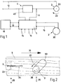
- the processing machine 2 has a drive motor 20.
- This drive motor 20 sets the processing tool, which is not shown here, in rotation 22.
- an electric motor is provided as the drive motor 20.
- This electric motor is connected to a power supply 12.
- the cutting performance of the tool is reduced due to the worn or used tool. This results in an overload of the motor, whereby the motor tries to reach its nominal speed again by increasing the current consumption.
- a resistor 40 is provided in line 12, for example. Due to the reduced speed, the drive motor 20 draws more current. This leads to an increased voltage drop across the resistor 40, which is picked up by the controller 1 via the line 11.
- a large number of lines connect to the controller 1.
- the controller 1 is connected to an input field 10 via the line 13.
- Various data can be entered into the controller 1 via the input field 10. For example, it is possible to enter a minimum speed by entering 10. If the speed is above the minimum speed, the feed speed is not changed. The alternating speed can also be specified with the aid of the input 10.
- a large number of further lines 14 are connected to the controller, through which the controller 1 is connected to further elements, for example data memories, computers, etc.
- the controller 1 is connected to the conveying device 3 via the line 15.
- the controller 1 acts on the drive motor 30 of the conveyor device 3.
- the speed 22 measured by the speed sensor or load sensor 4 now drops below that entered via the input field 10 Minimum speed, the drive motor 30 is influenced via the control line 15 in such a way that the feed speed of the workpiece 5 is reduced.
- the controller 1 provides that the feed speed of the conveying device 3 is also increased, that is to say the drive motor 30 becomes correspondingly faster.
- a direct proportionality can be assumed here.
- FIG. 2 schematically shows how the processing machines 2 act on a workpiece 5.
- a wooden beam is provided as the workpiece 5.
- the circular saw 23 With the circular saw 23, a longitudinal cut 24 is made in the workpiece 5.
- An actuator 25 is provided for positioning the circular saw 23. In this embodiment, this causes the circular saw blade 23 to be displaced parallel to the conveying direction 31.
- an end mill 26 is indicated in FIG. 2 on the right side.
- This end mill cuts an oblique groove 50 into the workpiece 5.
- This groove 50 can now be introduced in two different ways.
- the conveying device 3 can be stopped and the tool 26 can be displaced obliquely along the arrow 21 by the movement drive 25.
- the angle between the conveying direction and the machining direction is not a vectorial approach, but a way of looking that is independent of a forward or backward movement.
- the actuator 25 is now arranged, for example, at an angle which deviates from the right angle with respect to the conveying direction 31, this means for the control only a correction by a trigonometric factor which depends on this angle.
Landscapes
- Engineering & Computer Science (AREA)
- Mechanical Engineering (AREA)
- Life Sciences & Earth Sciences (AREA)
- Wood Science & Technology (AREA)
- Forests & Forestry (AREA)
- Dovetailed Work, And Nailing Machines And Stapling Machines For Wood (AREA)
- Automatic Control Of Machine Tools (AREA)
Applications Claiming Priority (2)
| Application Number | Priority Date | Filing Date | Title |
|---|---|---|---|
| DE19617335A DE19617335A1 (de) | 1996-04-30 | 1996-04-30 | Abbundanlage zum Bearbeiten von Werkstücken mit einer Fördervorrichtung |
| DE19617335 | 1996-04-30 |
Publications (1)
| Publication Number | Publication Date |
|---|---|
| EP0804998A1 true EP0804998A1 (fr) | 1997-11-05 |
Family
ID=7792927
Family Applications (1)
| Application Number | Title | Priority Date | Filing Date |
|---|---|---|---|
| EP97106074A Withdrawn EP0804998A1 (fr) | 1996-04-30 | 1997-04-14 | Machine de taillage pour l'usinage des pièces à usiner avec un dispositif d'avancement |
Country Status (2)
| Country | Link |
|---|---|
| EP (1) | EP0804998A1 (fr) |
| DE (1) | DE19617335A1 (fr) |
Families Citing this family (1)
| Publication number | Priority date | Publication date | Assignee | Title |
|---|---|---|---|---|
| DE19716971C9 (de) * | 1997-04-15 | 2012-05-31 | R.M.G. Schmidler Gmbh | Abbundanlage |
Citations (4)
| Publication number | Priority date | Publication date | Assignee | Title |
|---|---|---|---|---|
| US3602090A (en) * | 1970-02-27 | 1971-08-31 | Boeing Co | Milling machine control system and milling force sensor therefor |
| EP0164063A2 (fr) * | 1984-05-29 | 1985-12-11 | Hundegger, Hans | Machine-outil pour l'usinage des planches |
| US4698773A (en) * | 1986-01-31 | 1987-10-06 | The Boeing Company | Adaptive feed rate override system for a milling machine |
| US4802095A (en) * | 1986-12-24 | 1989-01-31 | The Boeing Company | Method for indicating end mill wear |
-
1996
- 1996-04-30 DE DE19617335A patent/DE19617335A1/de not_active Withdrawn
-
1997
- 1997-04-14 EP EP97106074A patent/EP0804998A1/fr not_active Withdrawn
Patent Citations (5)
| Publication number | Priority date | Publication date | Assignee | Title |
|---|---|---|---|---|
| US3602090A (en) * | 1970-02-27 | 1971-08-31 | Boeing Co | Milling machine control system and milling force sensor therefor |
| EP0164063A2 (fr) * | 1984-05-29 | 1985-12-11 | Hundegger, Hans | Machine-outil pour l'usinage des planches |
| DE3420080C1 (de) * | 1984-05-29 | 1989-11-02 | Konrad 8011 Faistenhaar Frey | Abbundmaschine zum Bearbeiten von Brettern,Kanthoelzern und dergleichen |
| US4698773A (en) * | 1986-01-31 | 1987-10-06 | The Boeing Company | Adaptive feed rate override system for a milling machine |
| US4802095A (en) * | 1986-12-24 | 1989-01-31 | The Boeing Company | Method for indicating end mill wear |
Also Published As
| Publication number | Publication date |
|---|---|
| DE19617335A1 (de) | 1997-11-06 |
Similar Documents
| Publication | Publication Date | Title |
|---|---|---|
| EP0242352B1 (fr) | Dispositif pour l'enlevement de copeaux des parties laterales de troncs d'arbres | |
| DD289967B5 (de) | Verfahren und Vorrichtung zur Herstellung von Holzlamellen aus Schnittholz | |
| DE19622374B4 (de) | Verfahren und Vorrichtung zur Regelung der Zerspannungsleistung einer Säge | |
| EP0261568B1 (fr) | Machine à travailler le bois | |
| DE3345875A1 (de) | Metall-saegeschneider und steuervorrichtung fuer einen metall-saegeschneider | |
| DE4419324C2 (de) | Vorrichtung zum Bearbeiten von Holz | |
| WO1985005062A1 (fr) | Installation de sciage et de coupe pour troncs d'arbre | |
| EP0804998A1 (fr) | Machine de taillage pour l'usinage des pièces à usiner avec un dispositif d'avancement | |
| DE2947993C2 (fr) | ||
| EP0292864B1 (fr) | Machine pour travailler le bois | |
| EP0813941B2 (fr) | Machine-outil pour l'usinage de pièces allongées | |
| DE2151804B2 (de) | Umlaufender Messerkopf einer Schal maschine fur Draht oder Stangen material | |
| DE102004010334A1 (de) | Verfahren zum Sägen von Hölzern | |
| DE1503937A1 (de) | Verfahren zum Saegen von Staemmen zu Brettern,Planken und Schwellen | |
| WO2019057658A1 (fr) | Procédé d'usinage de pièces, produit programme-informatique, et installation d'usinage de pièces | |
| EP2808138B1 (fr) | Agencement de dispositif de coupe et procédé de coupe | |
| DE29817770U1 (de) | Spanabhende Werkzeugmaschine, insbesondere Holzbearbeitungsmaschine für Fenster-, Tür- und Fassadenprofile sowie Werkzeugaggregate für eine Werkzeugmaschine | |
| DE19905414C2 (de) | Vorrichtung zum Schneiden und Einkerben von Profilen | |
| DE4408886A1 (de) | Einrichtung zur Regelung der Schnittgeschwindigkeit einer Säge mit Sägeblatt | |
| DE3717411C2 (fr) | ||
| DE19917537C5 (de) | Holzbearbeitungsmaschine mit einer Korrekturvorrichtung | |
| DE4107946A1 (de) | Verfahren und vorrichtung zum fraesen von werkstuecken aus holz oder holzaehnlichem material | |
| EP3640754B1 (fr) | Dispositif et procédé d'usinage de pièces | |
| AT406129B (de) | Vorrichtung zum spanabhebenden bearbeiten einer streifenförmigen werkstückfläche | |
| DE9421744U1 (de) | Einrichtung zur Regelung der Schnittgeschwindigkeit einer Säge mit Sägeblatt |
Legal Events
| Date | Code | Title | Description |
|---|---|---|---|
| PUAI | Public reference made under article 153(3) epc to a published international application that has entered the european phase |
Free format text: ORIGINAL CODE: 0009012 |
|
| AK | Designated contracting states |
Kind code of ref document: A1 Designated state(s): AT CH DE IT LI |
|
| 17P | Request for examination filed |
Effective date: 19971218 |
|
| 17Q | First examination report despatched |
Effective date: 19991229 |
|
| GRAH | Despatch of communication of intention to grant a patent |
Free format text: ORIGINAL CODE: EPIDOS IGRA |
|
| STAA | Information on the status of an ep patent application or granted ep patent |
Free format text: STATUS: THE APPLICATION IS DEEMED TO BE WITHDRAWN |
|
| 18D | Application deemed to be withdrawn |
Effective date: 20031105 |