EP0805003A2 - Appareil de scellement de chevilles actionné par la poudre - Google Patents
Appareil de scellement de chevilles actionné par la poudre Download PDFInfo
- Publication number
- EP0805003A2 EP0805003A2 EP97107296A EP97107296A EP0805003A2 EP 0805003 A2 EP0805003 A2 EP 0805003A2 EP 97107296 A EP97107296 A EP 97107296A EP 97107296 A EP97107296 A EP 97107296A EP 0805003 A2 EP0805003 A2 EP 0805003A2
- Authority
- EP
- European Patent Office
- Prior art keywords
- barrel
- piston
- piston head
- bolt
- section
- Prior art date
- Legal status (The legal status is an assumption and is not a legal conclusion. Google has not performed a legal analysis and makes no representation as to the accuracy of the status listed.)
- Granted
Links
- 239000007789 gas Substances 0.000 claims abstract description 13
- 239000000567 combustion gas Substances 0.000 claims abstract description 10
- 238000009423 ventilation Methods 0.000 claims abstract description 9
- 238000013016 damping Methods 0.000 claims description 3
- 230000036316 preload Effects 0.000 claims 2
- 238000002485 combustion reaction Methods 0.000 description 2
- 238000010304 firing Methods 0.000 description 2
- 238000000034 method Methods 0.000 description 2
- 230000003252 repetitive effect Effects 0.000 description 2
- 238000007789 sealing Methods 0.000 description 2
- 230000015572 biosynthetic process Effects 0.000 description 1
- 238000010276 construction Methods 0.000 description 1
- 230000001771 impaired effect Effects 0.000 description 1
- 230000007704 transition Effects 0.000 description 1
Images
Classifications
-
- B—PERFORMING OPERATIONS; TRANSPORTING
- B25—HAND TOOLS; PORTABLE POWER-DRIVEN TOOLS; MANIPULATORS
- B25C—HAND-HELD NAILING OR STAPLING TOOLS; MANUALLY OPERATED PORTABLE STAPLING TOOLS
- B25C1/00—Hand-held nailing tools; Nail feeding devices
- B25C1/08—Hand-held nailing tools; Nail feeding devices operated by combustion pressure
- B25C1/10—Hand-held nailing tools; Nail feeding devices operated by combustion pressure generated by detonation of a cartridge
- B25C1/14—Hand-held nailing tools; Nail feeding devices operated by combustion pressure generated by detonation of a cartridge acting on an intermediate plunger or anvil
Definitions
- the invention relates to a powder-operated bolt-actuating device according to the preamble of claim 1.
- a powder-operated bolt-actuating device with a barrel guided in a barrel guide sleeve, which can be brought into operative engagement with a closure piece, the barrel guide bore of which receives a multi-part piston, the mouth-side part of which has a piston skirt and a piston head, and which faces away from the mouth Side has a cartridge storage.
- the piston includes a so-called hammer consisting of a sleeve and a shaft, which serves to reduce the recoil occurring when the bolt is inserted so much that the device does not rise from the wall into which the bolt penetrates.
- the circumference of the piston head can be provided with grooves which connect the spaces in front of and behind the piston head with one another.
- it is not a repetitive device, so that the piston is not returned to its starting position by using the combustion gases.
- the object of the invention is to provide a powder-operated bolt-actuating device according to the preamble of claim 1, which is simplified in construction as a repetitive device.
- the combustion gases are throttled through the piston head from the back to the front, where they pass through outlet openings into an annular space between the piston skirt and barrel guide bore for the piston and build up a gas cushion there.
- These outlet openings are surrounded by an annular spring which, when the pressure in the annular space at the front of the piston becomes greater than that at the rear, closes the outlet openings.
- the formation of the gas cushion is supported by the air contained in the annular space and compressed by the piston movement. This gas cushion not only intercepts the piston, but also acts as a gas spring, since the pressure behind the piston drops by releasing appropriate ventilation slots in the barrel rather than the pressure of the gas cushion, so that the latter is thereby returned to its starting position.
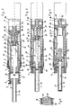
- Fig. 1 shows a section in section of the barrel-side part of a powder-operated bolt-actuating device in its initial position.
- FIG 2 and 3 show the detail of the bolt setting device before the bolt setting process or at the end of the bolt setting process.
- FIG. 4 shows an enlarged detail “A” from FIG. 2.
- the powder-operated bolt setting device shown comprises a barrel guide sleeve 1, which mounts a sleeve-shaped insert 2 on the muzzle side.
- the insert 2 accommodates a bolt guide 3 which is displaceable therein and which is provided with a shoulder 4 which, in the starting position of FIG. 1, bears against an inwardly directed flange section 5 of a threaded piece 6 screwed onto the barrel guide sleeve 1 on the mouth side.
- a helical spring 9 is clamped between the flange section 5 and an outwardly directed flange section 7 of a threaded piece 8 screwed onto the bolt guide 3 prestresses the bolt guide 3 in the starting position of FIG. 1.
- the bolt guide 3 has a bore 10 for receiving a bolt to be inserted, which is widened on the side facing away from the muzzle to slidably receive the muzzle-side end of a barrel front part 11, while the insert 2 serves as a safety stop for the barrel front part 11 when the device is without Loading a bolt should be operated.
- a barrel rear part 12 is provided, which is inserted with an extension 13 in the barrel front part 11 and in which a piston receptacle 14 and a combustion chamber are formed adjacent to a conical barrel floor 15.
- a cartridge bearing 16 is also provided in the rear barrel part 12 for receiving a cartridge, a narrowing bore 17 opening into the running floor 15 adjoining the cartridge bearing 16.
- Adjacent to the cartridge store 16 is a closure piece 18 having a cartridge tape guide.
- the rear barrel part 12 is connected via one or more tie rods 19 to the bolt guide 3 in such a way that the distance between the two can vary within predetermined limits, which are determined by an axial groove 20 in which the mouth end of the tie rod 19 can be displaced.
- the pull rod 19 expediently has hook-shaped ends with which it is hooked into the axial groove 20 or a corresponding recess in the rear barrel part 12.
- a piston 21 which has a piston head 22 and a piston shaft 23.
- the piston shaft 23 is displaceable up to the mouth side of the bore 10 of the pin guide 3 (FIG. 3).
- the piston head 22 has a section 24 which is received in the starting position by the piston receptacle 14 of the rear barrel part 12 and a section 25 with an enlarged diameter which is guided by the barrel guide bore 26 of the barrel front part 11.
- piston 21 has a transition piece with a conical mouth-side end 27, to which a conical receptacle 28 is assigned at the mouth-side end of barrel front part 11, and an adjoining cylindrical section 29 adjacent to section 25.
- a damping disk 30 can be arranged on the end face of the barrel front part 11 from which the piston shaft 23 projects.
- the barrel front part 11 is provided at its end engaging with the barrel rear part 12 with a plurality of ventilation slots 31 distributed over its circumference, which are practically covered by the section 25 of the piston 21 in the starting position of FIG. 1.
- the ventilation slots 31 open into an annular space formed by a twist 32 at the end of the barrel front part 11 and surrounded by the barrel guide sleeve 1.
- the barrel guide sleeve 1 is provided with corresponding ventilation openings 33, so that the ventilation slots 31 can be connected to the outside.
- An annular space 34 around the piston skirt 23 in the barrel guide bore 26 is connected to the rear of the piston head 22 via an axial bore 35 and a transverse bore 36.
- the orifices of the transverse bore 36 in the annular space 34 are located in the cylindrical section 29 in front of the section 25 of the piston head 22 and are surrounded by an annular spring 37, which is accommodated with play by a corresponding groove in the section 29, cf. in particular Fig. 4.
- the bolt guide 3 receives a corresponding bolt (not shown).
- the bolt-setting tool is placed on a wall or the like in which the bolt is to be placed and is brought into the firing position by pressing against the wall (FIG. 2).
- the pin guide 3 is pressed against the force of the coil spring 9 into the barrel guide sleeve 1 until the coil spring 9 is compressed, so that the barrel front part 11 and the barrel rear part 12 are moved backwards, so that the cartridge bearing 16 receives a cartridge and in the firing position with respect to the closure piece 18 is brought.
- the resulting combustion gases cause the piston 21 to move abruptly forward in the barrel 11, 12 to the mouth side, but a part of the combustion gases through the axial bore 35 and the transverse bore 36 into the annular space which is reduced by the piston movement 34 flows.
- the air in the annulus becomes with the incoming combustion gases 34 compressed until the conical end 27 reaches its receptacle 28 in the barrel front part 11 (Fig. 3).
- the bolt is then set and the gas in the annular space 34 is compressed.
- the gas volume compressed in the annular space 34 is built up due to the sealing of the annular space 34 by the section 25 of the piston 21 with respect to the barrel guide bore 26 and by the piston skirt 23 and the adjoining conical section 27 on the outlet side of the barrel front part 11 and catches the piston 21 from.
- the gas volume compressed in the annular space 34 expands again due to the pressure drop on the rear of the piston and thereby returns the piston 21 to its starting position, in which the section 25 of the piston head 22 is received by the rear barrel part 12 and the section 24 of the piston head 22 is adjacent to the barrel rear part 12.
- Leakage losses on the sealing surfaces must of course be kept so low that the gas volume acting as a gas spring in the annular space 34 can exert sufficient force to return the piston 21 to its starting position.
Landscapes
- Engineering & Computer Science (AREA)
- Chemical & Material Sciences (AREA)
- Combustion & Propulsion (AREA)
- Mechanical Engineering (AREA)
- Portable Nailing Machines And Staplers (AREA)
- Packaging Of Annular Or Rod-Shaped Articles, Wearing Apparel, Cassettes, Or The Like (AREA)
- Cleaning In General (AREA)
- Powder Metallurgy (AREA)
- Fertilizing (AREA)
- Catching Or Destruction (AREA)
Applications Claiming Priority (3)
| Application Number | Priority Date | Filing Date | Title |
|---|---|---|---|
| DE19617672A DE19617672C1 (de) | 1996-05-03 | 1996-05-03 | Pulverkraftbetriebenes Bolzensetzgerät |
| DE19617672 | 1996-05-03 | ||
| US09/094,166 US6085958A (en) | 1996-05-03 | 1998-06-09 | Explosive powder charge operated bolt-setting tool |
Publications (3)
| Publication Number | Publication Date |
|---|---|
| EP0805003A2 true EP0805003A2 (fr) | 1997-11-05 |
| EP0805003A3 EP0805003A3 (fr) | 1998-02-04 |
| EP0805003B1 EP0805003B1 (fr) | 2001-07-04 |
Family
ID=26025334
Family Applications (1)
| Application Number | Title | Priority Date | Filing Date |
|---|---|---|---|
| EP97107296A Expired - Lifetime EP0805003B1 (fr) | 1996-05-03 | 1997-05-02 | Appareil de scellement de chevilles actionné par la poudre |
Country Status (5)
| Country | Link |
|---|---|
| US (1) | US6085958A (fr) |
| EP (1) | EP0805003B1 (fr) |
| AT (1) | ATE202738T1 (fr) |
| DE (2) | DE19617672C1 (fr) |
| ES (1) | ES2171240T3 (fr) |
Families Citing this family (11)
| Publication number | Priority date | Publication date | Assignee | Title |
|---|---|---|---|---|
| US6705409B2 (en) | 2001-03-22 | 2004-03-16 | Chicago Pneumatic Tool Company | Reciprocating tool having a piston retaining system |
| US7051528B2 (en) * | 2001-08-17 | 2006-05-30 | Yves Daunas | Autonomous gas powered ram |
| FR2855542B1 (fr) * | 2003-05-26 | 2005-08-05 | Freyssinet Int Stup | Procede de surblocage d'au moins un toron dans un bloc d'ancrage et systeme de surblocage d'au moins un toron dans un bloc d'ancrage |
| DE10341384B4 (de) * | 2003-09-05 | 2016-06-23 | Hilti Aktiengesellschaft | Setzgerät |
| DE10358578A1 (de) * | 2003-12-15 | 2005-07-14 | Hilti Ag | Brennkraftbetriebenes Setzgerät |
| US7287679B2 (en) * | 2004-07-28 | 2007-10-30 | Powers Products Iii, Llc | Powder activated setting tool piston retainer arrangement and method |
| US7201302B2 (en) * | 2004-09-01 | 2007-04-10 | Illinois Tool Works Inc. | Driver blade with auxiliary combustion chamber for combustion powered fastener-driving tool |
| US7328751B2 (en) * | 2004-10-28 | 2008-02-12 | Fci Americas Technology, Inc. | Powder operated tool |
| DE102005000106B4 (de) * | 2005-08-25 | 2014-02-27 | Hilti Aktiengesellschaft | Setzgerät |
| CA2726559C (fr) * | 2009-12-30 | 2014-02-11 | Hubbel Incorporated | Outil a charge explosive et connecteur |
| US10926389B2 (en) * | 2018-07-31 | 2021-02-23 | Chung-Heng Lee | Powder-actuated tool |
Family Cites Families (21)
| Publication number | Priority date | Publication date | Assignee | Title |
|---|---|---|---|---|
| US2877750A (en) * | 1957-05-29 | 1959-03-17 | Olin Mathieson | Hammer and buffer mechanism |
| FR1289689A (fr) * | 1960-04-06 | 1962-04-06 | Appareil pour l'enfoncement de boulons notamment dans des maçonneries | |
| US3044071A (en) * | 1960-04-06 | 1962-07-17 | Behrend Herbert | Explosive actuated tool |
| DE1177087B (de) * | 1961-04-28 | 1964-08-27 | Tornado Gmbh | Geraet zum Eintreiben von Bolzen u. dgl. |
| DE1503009B2 (de) * | 1963-08-26 | 1970-07-16 | Omark Industries Inc., Portland, Oreg. (V.St.A.) | Abfangeinrichtung für den Schubkolben eines Brennkraftbolzensetzers |
| US3255942A (en) * | 1964-06-12 | 1966-06-14 | Star Expansion Ind Corp | Piston tool with fastener resetting arrangement |
| US3297224A (en) * | 1965-04-30 | 1967-01-10 | Olin Mathieson | Power actuated tool |
| US3496840A (en) * | 1968-01-29 | 1970-02-24 | Fastener Corp | Fastener driving apparatus |
| US3690536A (en) * | 1970-12-07 | 1972-09-12 | Olin Corp | Powder-actuated tool |
| US3744240A (en) * | 1971-11-05 | 1973-07-10 | Olin Corp | Fastener driving tool |
| US3815475A (en) * | 1972-11-20 | 1974-06-11 | Signode Corp | Fastener driving tool with improved piston return |
| AU460558B2 (en) * | 1974-06-11 | 1975-04-11 | Olin Corporation | Power-actuated tool |
| GB2045673B (en) * | 1979-04-10 | 1983-03-23 | Prospection & Inventions | Powder actuated piston tool with power adjustment |
| US4358041A (en) * | 1980-06-12 | 1982-11-09 | Olin Corporation | Powder-actuated tool with power adjustment and angle-fire control |
| DE3540953A1 (de) * | 1985-11-19 | 1987-05-21 | Hilti Ag | Pulverkraftbetriebenes bolzensetzgeraet |
| US4753151A (en) * | 1986-06-27 | 1988-06-28 | Lockheed Corporation | Self-retracting ballistic actuator system |
| FR2608493B1 (fr) * | 1986-12-23 | 1994-09-02 | Prospection & Inventions | Appareil de scellement a tir indirect |
| DE3819813A1 (de) * | 1988-06-10 | 1989-12-14 | Hilti Ag | Pulverkraftbetriebenes setzgeraet |
| DE4022674A1 (de) * | 1990-07-17 | 1992-01-23 | Hilti Ag | Pulverkraftbetriebenes setzgeraet |
| DE4313504A1 (de) * | 1993-04-24 | 1994-10-27 | Hilti Ag | Pulverkraftbetriebenes Setzgerät |
| FR2746690B1 (fr) * | 1996-03-26 | 1998-05-29 | Spit Soc Prospect Inv Techn | Appareil d'entrainement de tampon par masselotte a retour automatique en position du tir |
-
1996
- 1996-05-03 DE DE19617672A patent/DE19617672C1/de not_active Expired - Fee Related
-
1997
- 1997-05-02 AT AT97107296T patent/ATE202738T1/de not_active IP Right Cessation
- 1997-05-02 ES ES97107296T patent/ES2171240T3/es not_active Expired - Lifetime
- 1997-05-02 EP EP97107296A patent/EP0805003B1/fr not_active Expired - Lifetime
- 1997-05-02 DE DE59703936T patent/DE59703936D1/de not_active Expired - Fee Related
-
1998
- 1998-06-09 US US09/094,166 patent/US6085958A/en not_active Expired - Fee Related
Also Published As
| Publication number | Publication date |
|---|---|
| EP0805003A3 (fr) | 1998-02-04 |
| EP0805003B1 (fr) | 2001-07-04 |
| DE59703936D1 (de) | 2001-08-09 |
| US6085958A (en) | 2000-07-11 |
| DE19617672C1 (de) | 1997-10-09 |
| ES2171240T3 (es) | 2002-09-01 |
| ATE202738T1 (de) | 2001-07-15 |
Similar Documents
| Publication | Publication Date | Title |
|---|---|---|
| DE19617671C1 (de) | Pulverkraftbetriebenes Bolzensetzgerät | |
| DE2559238A1 (de) | Gasbetaetigte vorrichtung fuer den antrieb der nachladeeinrichtung eines automatischen gewehrs mit gasabzapfung | |
| DE19617672C1 (de) | Pulverkraftbetriebenes Bolzensetzgerät | |
| DE19547859A1 (de) | Pulverkraftbetriebenes Setzgerät | |
| DE3844489A1 (de) | Kraftstoffeinspritzvorrichtung | |
| EP0732178B1 (fr) | Outil de scellement de chevilles | |
| DE3732561A1 (de) | Verriegelbarer hydraulikzylinder | |
| EP0720893A1 (fr) | Appareil de scellement de chevilles actionné par de la poudre | |
| DE69013355T2 (de) | Projektil zur streuung einer last in form einer pyrotechnischen ladung. | |
| DE3150675A1 (de) | Zuendvorrichtung fuer verbrennungsmotoren mit innerer verbrennung und selbstzuendung | |
| DE3237324A1 (de) | Hydraulisches vorspanngeraet fuer eine schraubenverbindung | |
| DE10105881A1 (de) | Kolbenhalterung | |
| DE102011107751A1 (de) | Gasabnahmeanordnung für einen Lauf einer Waffe | |
| DE4009050C2 (fr) | ||
| EP4452559B1 (fr) | Dispositif et procédé d'enfoncement | |
| DE2326527A1 (de) | Verschlussanordnung | |
| DE2319152A1 (de) | Werkzeug, vorzugsweise pistole, zum einschiessen von befestigungsmitteln | |
| EP1052470A2 (fr) | Garniture pour l'évacuation des gaz de combustion d'un tube de canon | |
| DE3919761C2 (de) | Geschütz für flüssige Treibladungen | |
| EP1040271A1 (fr) | Soupape d'injection de carburant pour moteur a combustion interne | |
| DE102022118331A1 (de) | Nagelschussgerät, Verfahren zum Umbauen sowie Verfahren zur Nutzung eines solchen | |
| DE3211535C2 (de) | Luftgewehr | |
| DE19818714C2 (de) | Blockiervorrichtung für bewegliche Anschlüsse von Schalldämpfern an halbautomatischen Waffen | |
| AT355524B (de) | Patronenkammer fuer ein bolzensetzgeraet | |
| DE2053098C3 (de) | Hydropneumatischer Rohrvorholer für Geschütze |
Legal Events
| Date | Code | Title | Description |
|---|---|---|---|
| PUAI | Public reference made under article 153(3) epc to a published international application that has entered the european phase |
Free format text: ORIGINAL CODE: 0009012 |
|
| AK | Designated contracting states |
Kind code of ref document: A2 Designated state(s): AT CH DE ES FI FR GB IT LI SE |
|
| PUAL | Search report despatched |
Free format text: ORIGINAL CODE: 0009013 |
|
| AK | Designated contracting states |
Kind code of ref document: A3 Designated state(s): AT CH DE ES FI FR GB IT LI SE |
|
| 17P | Request for examination filed |
Effective date: 19980128 |
|
| RAP1 | Party data changed (applicant data changed or rights of an application transferred) |
Owner name: BERNER GMBH |
|
| GRAG | Despatch of communication of intention to grant |
Free format text: ORIGINAL CODE: EPIDOS AGRA |
|
| GRAG | Despatch of communication of intention to grant |
Free format text: ORIGINAL CODE: EPIDOS AGRA |
|
| 17Q | First examination report despatched |
Effective date: 19991007 |
|
| GRAG | Despatch of communication of intention to grant |
Free format text: ORIGINAL CODE: EPIDOS AGRA |
|
| GRAH | Despatch of communication of intention to grant a patent |
Free format text: ORIGINAL CODE: EPIDOS IGRA |
|
| GRAH | Despatch of communication of intention to grant a patent |
Free format text: ORIGINAL CODE: EPIDOS IGRA |
|
| GRAA | (expected) grant |
Free format text: ORIGINAL CODE: 0009210 |
|
| AK | Designated contracting states |
Kind code of ref document: B1 Designated state(s): AT CH DE ES FI FR GB IT LI SE |
|
| RAP1 | Party data changed (applicant data changed or rights of an application transferred) |
Owner name: BERNER GMBH |
|
| REF | Corresponds to: |
Ref document number: 202738 Country of ref document: AT Date of ref document: 20010715 Kind code of ref document: T |
|
| REG | Reference to a national code |
Ref country code: CH Ref legal event code: EP |
|
| REF | Corresponds to: |
Ref document number: 59703936 Country of ref document: DE Date of ref document: 20010809 |
|
| ITF | It: translation for a ep patent filed | ||
| GBT | Gb: translation of ep patent filed (gb section 77(6)(a)/1977) |
Effective date: 20010921 |
|
| ET | Fr: translation filed | ||
| REG | Reference to a national code |
Ref country code: CH Ref legal event code: NV Representative=s name: TROESCH SCHEIDEGGER WERNER AG |
|
| REG | Reference to a national code |
Ref country code: GB Ref legal event code: IF02 |
|
| PG25 | Lapsed in a contracting state [announced via postgrant information from national office to epo] |
Ref country code: GB Free format text: LAPSE BECAUSE OF NON-PAYMENT OF DUE FEES Effective date: 20020502 Ref country code: FI Free format text: LAPSE BECAUSE OF NON-PAYMENT OF DUE FEES Effective date: 20020502 Ref country code: AT Free format text: LAPSE BECAUSE OF NON-PAYMENT OF DUE FEES Effective date: 20020502 |
|
| PG25 | Lapsed in a contracting state [announced via postgrant information from national office to epo] |
Ref country code: SE Free format text: LAPSE BECAUSE OF NON-PAYMENT OF DUE FEES Effective date: 20020503 Ref country code: ES Free format text: LAPSE BECAUSE OF NON-PAYMENT OF DUE FEES Effective date: 20020503 |
|
| PLBE | No opposition filed within time limit |
Free format text: ORIGINAL CODE: 0009261 |
|
| STAA | Information on the status of an ep patent application or granted ep patent |
Free format text: STATUS: NO OPPOSITION FILED WITHIN TIME LIMIT |
|
| PG25 | Lapsed in a contracting state [announced via postgrant information from national office to epo] |
Ref country code: LI Free format text: LAPSE BECAUSE OF NON-PAYMENT OF DUE FEES Effective date: 20020531 Ref country code: CH Free format text: LAPSE BECAUSE OF NON-PAYMENT OF DUE FEES Effective date: 20020531 |
|
| 26N | No opposition filed | ||
| REG | Reference to a national code |
Ref country code: ES Ref legal event code: FG2A Ref document number: 2171240 Country of ref document: ES Kind code of ref document: T3 |
|
| PG25 | Lapsed in a contracting state [announced via postgrant information from national office to epo] |
Ref country code: DE Free format text: LAPSE BECAUSE OF NON-PAYMENT OF DUE FEES Effective date: 20021203 |
|
| GBPC | Gb: european patent ceased through non-payment of renewal fee |
Effective date: 20020502 |
|
| EUG | Se: european patent has lapsed | ||
| REG | Reference to a national code |
Ref country code: CH Ref legal event code: PL |
|
| PG25 | Lapsed in a contracting state [announced via postgrant information from national office to epo] |
Ref country code: FR Free format text: LAPSE BECAUSE OF NON-PAYMENT OF DUE FEES Effective date: 20030131 |
|
| REG | Reference to a national code |
Ref country code: FR Ref legal event code: ST |
|
| REG | Reference to a national code |
Ref country code: ES Ref legal event code: FD2A Effective date: 20030611 |
|
| PG25 | Lapsed in a contracting state [announced via postgrant information from national office to epo] |
Ref country code: IT Free format text: LAPSE BECAUSE OF NON-PAYMENT OF DUE FEES Effective date: 20050502 |