EP0805031B1 - Moyens pour positionner un assemblage de paupière à une tête d'une imprimante à jet d'encre continu - Google Patents
Moyens pour positionner un assemblage de paupière à une tête d'une imprimante à jet d'encre continu Download PDFInfo
- Publication number
- EP0805031B1 EP0805031B1 EP19970302695 EP97302695A EP0805031B1 EP 0805031 B1 EP0805031 B1 EP 0805031B1 EP 19970302695 EP19970302695 EP 19970302695 EP 97302695 A EP97302695 A EP 97302695A EP 0805031 B1 EP0805031 B1 EP 0805031B1
- Authority
- EP
- European Patent Office
- Prior art keywords
- eyelid
- catcher
- assembly
- ink jet
- printhead
- Prior art date
- Legal status (The legal status is an assumption and is not a legal conclusion. Google has not performed a legal analysis and makes no representation as to the accuracy of the status listed.)
- Expired - Lifetime
Links
- 210000000744 eyelid Anatomy 0.000 title claims description 55
- 230000013011 mating Effects 0.000 claims description 2
- 239000000853 adhesive Substances 0.000 description 5
- 230000001070 adhesive effect Effects 0.000 description 5
- 239000012530 fluid Substances 0.000 description 3
- 238000007641 inkjet printing Methods 0.000 description 3
- 238000007789 sealing Methods 0.000 description 2
- 230000000712 assembly Effects 0.000 description 1
- 238000000429 assembly Methods 0.000 description 1
- 238000000151 deposition Methods 0.000 description 1
- 238000012986 modification Methods 0.000 description 1
- 230000004048 modification Effects 0.000 description 1
- 238000007639 printing Methods 0.000 description 1
- 239000002689 soil Substances 0.000 description 1
Images
Classifications
-
- B—PERFORMING OPERATIONS; TRANSPORTING
- B41—PRINTING; LINING MACHINES; TYPEWRITERS; STAMPS
- B41J—TYPEWRITERS; SELECTIVE PRINTING MECHANISMS, i.e. MECHANISMS PRINTING OTHERWISE THAN FROM A FORME; CORRECTION OF TYPOGRAPHICAL ERRORS
- B41J2/00—Typewriters or selective printing mechanisms characterised by the printing or marking process for which they are designed
- B41J2/005—Typewriters or selective printing mechanisms characterised by the printing or marking process for which they are designed characterised by bringing liquid or particles selectively into contact with a printing material
- B41J2/01—Ink jet
- B41J2/135—Nozzles
- B41J2/165—Prevention or detection of nozzle clogging, e.g. cleaning, capping or moistening for nozzles
- B41J2/16505—Caps, spittoons or covers for cleaning or preventing drying out
- B41J2/16508—Caps, spittoons or covers for cleaning or preventing drying out connected with the printer frame
-
- B—PERFORMING OPERATIONS; TRANSPORTING
- B41—PRINTING; LINING MACHINES; TYPEWRITERS; STAMPS
- B41J—TYPEWRITERS; SELECTIVE PRINTING MECHANISMS, i.e. MECHANISMS PRINTING OTHERWISE THAN FROM A FORME; CORRECTION OF TYPOGRAPHICAL ERRORS
- B41J2/00—Typewriters or selective printing mechanisms characterised by the printing or marking process for which they are designed
- B41J2/005—Typewriters or selective printing mechanisms characterised by the printing or marking process for which they are designed characterised by bringing liquid or particles selectively into contact with a printing material
- B41J2/01—Ink jet
- B41J2/17—Ink jet characterised by ink handling
- B41J2/1714—Conditioning of the outside of ink supply systems, e.g. inkjet collector cleaning, ink mist removal
-
- B—PERFORMING OPERATIONS; TRANSPORTING
- B41—PRINTING; LINING MACHINES; TYPEWRITERS; STAMPS
- B41J—TYPEWRITERS; SELECTIVE PRINTING MECHANISMS, i.e. MECHANISMS PRINTING OTHERWISE THAN FROM A FORME; CORRECTION OF TYPOGRAPHICAL ERRORS
- B41J2/00—Typewriters or selective printing mechanisms characterised by the printing or marking process for which they are designed
- B41J2/005—Typewriters or selective printing mechanisms characterised by the printing or marking process for which they are designed characterised by bringing liquid or particles selectively into contact with a printing material
- B41J2/01—Ink jet
- B41J2/17—Ink jet characterised by ink handling
- B41J2/18—Ink recirculation systems
- B41J2/185—Ink-collectors; Ink-catchers
Definitions
- the present invention relates to continuous ink jet printing and, more particularly, to registering the linkage that locates an eyelid assembly to a continuous ink jet printhead.
- Ink jet printing systems are known in which a printhead defines one or more rows of orifices which receive an electrically conductive recording fluid from a pressurized fluid supply manifold and eject the fluid in rows of parallel streams.
- Printers using such printheads accomplish graphic reproduction by selectively charging and deflecting the drops in each of the streams and depositing at least some of the drops on a print receiving medium, while others of the drops strike a drop catcher device.
- the eyelid diverts the flow of ink from a resonator back into the printhead while the printer is running but not printing.
- screws are used to fasten pivot plates into an ink jet printhead.
- a fixture is used to locate these pivot plates to an unimportant part of the printhead.
- the optimum relationship is between the catcher and the eyelid assembly. Without this relationship, tolerance is added by the assembly of many parts. Clearance holes for securing the pivot plates with screws also add additional tolerance. Screws require multidirectional directional assembly instead of the desired assembly, which adds labor costs. Furthermore, screws inherently increase part count to a product, which is also undesirable. Whatever means is used to align the catcher to the eyelid assembly, the more precise an alignment is, the better the eyelid operates.
- an eyelid assembly is precisely aligned to a catcher in a continuous ink jet printhead.
- An eyelid linkage mechanism associated with the eyelid assembly fastens to the ink jet printhead to provide pivot areas that allow the eyelid assembly to rotate in and out of the catcher.
- a fixture precisely holds and locates the eyelid linkage mechanism to accurately register the eyelid assembly to the catcher.
- the eyelid linkage mechanism is bonded to the printhead frame in reference to the catcher, to provide the pivot areas that allow the eyelid assembly to rotate in and out of the catcher.
- the accurately registered eyelid assembly is then secured to the eyelid linkage mechanism.
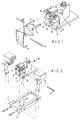
- a typical ink jet printhead generally designated 10 includes a resonator 2, a catcher 3, and an eyelid assembly 1.
- An eyelid linkage mechanism, or pivot plates 4, fasten to and travel with the ink jet printhead 10.
- the pivot plates are bonded into place, such as with an instant adhesive that is wicked or placed between identified bond sites 8 of the eyelid linkage 4 and a printhead frame 5.
- the pivot plates provide pivot areas that allow the eyelid assembly 1 to rotate in-and-out of the catcher 3, thereby diverting ink from the resonator 2 when actuated into the ink path and sealing against the catcher 3.
- the eyelid assembly 1 can be disconnected from the printhead 10 by pulling a pivot pin 7, receivable into pivot apertures 13, from the eyelid assembly 1 and linkage plates 4.
- the eyelid assembly 1 stays with the printer and the linkage plates go with the printhead.
- the precision design according to the present invention succeeds by establishing a direct locational relationship between the catcher 3 and the eyelid assembly 1. This accuracy is ensured by eliminating screws and their clearance holes, and by fixturing directly to the catcher 3 via precise alignment holes 6 located in the bottom of the catcher 3. Fixture 9 precisely holds and locates the eyelid links 4, and accurately registers to the catcher assembly via the catcher alignment holes 6 and associated mating pins 11. This creates the most accurate possible relationship between the eyelid assembly 1 and the catcher 3 by bypassing all of the hardware between these parts via the fixture. A bonding means can then be applied to bond sites 8, associated with the precisely aligned eyelid assembly 1 and catcher 3, to permanize the relationship between these parts.
- the bonding means can be any suitable means, including instant adhesive.
- the bond sites 8 preferably have a surface finish of 100-200 RMS to enhance mechanical interlocking of the bonding means.
- the printhead frame 5 utilizes capillary channels 12 to feed instant adhesive between the eyelid links 4 and the printhead frame 5 to the bond sites 8.
- An instant adhesive can be pre-applied to the printhead frame 5 or the eyelid links 4, as long as the positioning of the parts takes place before the adhesive dries, typically within 45 seconds.
- the present invention is useful in the field of ink jet printing, and has the advantage of maximizing print quality by allowing the print media to be particularly close to the printer.
- the present invention provides the further advantage of providing a precisely registered sealing surface between the eyelid assembly and the printhead.
- the registration system of the present invention provides the advantage of eliminating screws, thereby saving labor and assembly costs.
Landscapes
- Particle Formation And Scattering Control In Inkjet Printers (AREA)
- Ink Jet (AREA)
Claims (5)
- Moyen pour un alignement précis d'un ensemble de paupière avec un dispositif de saisie dans une tête d'impression à jet d'encre en continu, comprenant :un mécanisme de liaison de paupière associé à l'ensemble de paupière ;un dispositif de serrage pour le maintien et le positionnement, de façon précise, du mécanisme de liaison de paupière pour un alignement précis de l'ensemble de paupière avec le dispositif de saisie ;un moyen de connexion pour connecter le mécanisme de liaison de paupière sur le cadre de la tête d'impression selon le dispositif de saisie afin de prévoir des zones de pivotement permettant à l'ensemble de paupière de tourner vers l'intérieur et vers l'extérieur du dispositif de saisie ; etun moyen de verrouillage pour bloquer l'ensemble de paupière aligné, de façon précise, sur le mécanisme de liaison de paupière.
- Moyen pour un alignement précis d'un ensemble de paupière avec un dispositif de saisie selon la revendication 1, dans lequel les zones de pivotement comprennent un point de pivotement sur lequel tourne la paupière.
- Moyen pour un alignement précis d'un ensemble de paupière avec un dispositif de saisie selon la revendication 1, dans lequel le moyen de verrouillage comprend une broche de pivotement.
- Moyen pour un alignement précis d'un ensemble de paupière avec un dispositif de saisie selon la revendication 1, dans lequel le mécanisme de liaison de paupière est maintenu et positionné, de façon précise, par le dispositif de fixation effectuant un alignement précis avec l'ensemble de saisie via des trous d'alignement de dispositif de saisie et des broches d'adaptation associées.
- Moyen pour un alignement précis d'un ensemble de paupière avec un dispositif de saisie selon la revendication 1, dans lequel le dispositif de fixation est provisoire.
Applications Claiming Priority (2)
| Application Number | Priority Date | Filing Date | Title |
|---|---|---|---|
| US64023596A | 1996-04-30 | 1996-04-30 | |
| US640235 | 1996-04-30 |
Publications (2)
| Publication Number | Publication Date |
|---|---|
| EP0805031A1 EP0805031A1 (fr) | 1997-11-05 |
| EP0805031B1 true EP0805031B1 (fr) | 2000-01-19 |
Family
ID=24567398
Family Applications (1)
| Application Number | Title | Priority Date | Filing Date |
|---|---|---|---|
| EP19970302695 Expired - Lifetime EP0805031B1 (fr) | 1996-04-30 | 1997-04-21 | Moyens pour positionner un assemblage de paupière à une tête d'une imprimante à jet d'encre continu |
Country Status (5)
| Country | Link |
|---|---|
| EP (1) | EP0805031B1 (fr) |
| JP (1) | JPH1034942A (fr) |
| AU (1) | AU714037B2 (fr) |
| CA (1) | CA2203954A1 (fr) |
| DE (1) | DE69701163T2 (fr) |
Cited By (2)
| Publication number | Priority date | Publication date | Assignee | Title |
|---|---|---|---|---|
| US9962943B1 (en) | 2016-11-07 | 2018-05-08 | Eastman Kodak Company | Inkjet printhead assembly with compact repositionable shutter |
| US9969178B1 (en) | 2016-11-07 | 2018-05-15 | Eastman Kodak Company | Inkjet printhead assembly with repositionable shutter mechanism |
Families Citing this family (6)
| Publication number | Priority date | Publication date | Assignee | Title |
|---|---|---|---|---|
| US6247781B1 (en) * | 1998-12-14 | 2001-06-19 | Scitex Digital Printing, Inc. | Ink jet printhead with an improved eyelid system |
| US9566798B1 (en) | 2016-05-24 | 2017-02-14 | Eastman Kodak Company | Inkjet printhead assembly with repositionable shutter |
| US9623689B1 (en) | 2016-05-24 | 2017-04-18 | Eastman Kodak Company | Modular printhead assembly with common center rail |
| US9527319B1 (en) | 2016-05-24 | 2016-12-27 | Eastman Kodak Company | Printhead assembly with removable jetting module |
| US9789714B1 (en) | 2016-10-21 | 2017-10-17 | Eastman Kodak Company | Modular printhead assembly with tilted printheads |
| US10052868B1 (en) | 2017-05-09 | 2018-08-21 | Eastman Kodak Company | Modular printhead assembly with rail assembly having upstream and downstream rod segments |
Family Cites Families (4)
| Publication number | Priority date | Publication date | Assignee | Title |
|---|---|---|---|---|
| US4305079A (en) * | 1979-09-24 | 1981-12-08 | International Business Machines Corp. | Movable ink jet gutter |
| US4266231A (en) * | 1979-11-01 | 1981-05-05 | International Business Machines Corp. | Ink jet with retractable electrode and secondary ink catcher |
| US4928115A (en) * | 1988-10-31 | 1990-05-22 | Eastman Kodak Company | Continuous ink jet printer having remotely operable print head assembly |
| US5475410A (en) * | 1992-03-19 | 1995-12-12 | Scitex Digital Printing, Inc. | Seal for ink jet printhead |
-
1997
- 1997-04-21 EP EP19970302695 patent/EP0805031B1/fr not_active Expired - Lifetime
- 1997-04-21 DE DE1997601163 patent/DE69701163T2/de not_active Expired - Lifetime
- 1997-04-29 CA CA 2203954 patent/CA2203954A1/fr not_active Abandoned
- 1997-04-30 AU AU19932/97A patent/AU714037B2/en not_active Ceased
- 1997-04-30 JP JP11237897A patent/JPH1034942A/ja not_active Ceased
Cited By (2)
| Publication number | Priority date | Publication date | Assignee | Title |
|---|---|---|---|---|
| US9962943B1 (en) | 2016-11-07 | 2018-05-08 | Eastman Kodak Company | Inkjet printhead assembly with compact repositionable shutter |
| US9969178B1 (en) | 2016-11-07 | 2018-05-15 | Eastman Kodak Company | Inkjet printhead assembly with repositionable shutter mechanism |
Also Published As
| Publication number | Publication date |
|---|---|
| AU714037B2 (en) | 1999-12-16 |
| DE69701163D1 (de) | 2000-02-24 |
| DE69701163T2 (de) | 2000-09-14 |
| CA2203954A1 (fr) | 1997-10-30 |
| JPH1034942A (ja) | 1998-02-10 |
| AU1993297A (en) | 1997-11-06 |
| EP0805031A1 (fr) | 1997-11-05 |
Similar Documents
| Publication | Publication Date | Title |
|---|---|---|
| US4628332A (en) | Ink printhead with holder mount | |
| JP3208740B2 (ja) | ジグザグ配置インクジェット印字ヘッド | |
| US7118193B2 (en) | Liquid ejecting recording head and liquid ejecting recording apparatus | |
| US6565193B1 (en) | Component for a four color printhead module | |
| EP0512799B1 (fr) | Tête d'impression thermique à jet d'encre s'étendant sur la largeur de la page | |
| US4635080A (en) | Liquid injection recording apparatus | |
| EP0805031B1 (fr) | Moyens pour positionner un assemblage de paupière à une tête d'une imprimante à jet d'encre continu | |
| JPH05270099A (ja) | 熱インクジェットノズル配列 | |
| CN1997521A (zh) | 安装组件 | |
| EP0571786A2 (fr) | Structure d'alignement pour éléments d'une tête d'impression par jet d'encre | |
| US8500249B2 (en) | Printhead module for an inkjet printhead assembly | |
| CA2301864C (fr) | Procede de fabrication d'un appareil d'impression | |
| US6623113B2 (en) | Inkjet recording head including electrode assembly for deflecting ink droplets | |
| JPS62121061A (ja) | 多色インクジエツト印字ヘツド | |
| US5739830A (en) | Monolithic printheads for ink jet printing apparatus | |
| JPS60204343A (ja) | インクジエツト記録装置 | |
| JPH0631912A (ja) | インクジェットヘッド | |
| EP0791461B1 (fr) | Ensemble de montage à faibles contraintes pour générateur de gouttelettes | |
| US7703874B2 (en) | Inkjet head unit including a plurality of head elements attached to one another and a common nozzle plate and ink distribution manifold | |
| EP1000744A3 (fr) | Tête d'enregistrement à jet d'encre, cartouche d'enregistrement à jet d'encre et dispositif d'enregistrement | |
| CA2175726A1 (fr) | Collecteur a fond poreux pour ejections de gouttelettes d'encre | |
| EP0829359B1 (fr) | Tête d'enregistrement à jet d'encre et dispositif d'enregistrement à jet d'encre comportant une telle tête | |
| JPH07195684A (ja) | 高精度スタック可能インクジェットプリントバー及びその製造方法 | |
| EP0805035B1 (fr) | Plate-forme ombilicale amovible pour tête d'impression à jet d'encre continu | |
| EP0805026B1 (fr) | Procédé de brasage fort pour une tête d'impression à jet d'encre continu |
Legal Events
| Date | Code | Title | Description |
|---|---|---|---|
| PUAI | Public reference made under article 153(3) epc to a published international application that has entered the european phase |
Free format text: ORIGINAL CODE: 0009012 |
|
| AK | Designated contracting states |
Kind code of ref document: A1 Designated state(s): DE FR GB |
|
| 17P | Request for examination filed |
Effective date: 19980212 |
|
| GRAG | Despatch of communication of intention to grant |
Free format text: ORIGINAL CODE: EPIDOS AGRA |
|
| 17Q | First examination report despatched |
Effective date: 19990223 |
|
| GRAG | Despatch of communication of intention to grant |
Free format text: ORIGINAL CODE: EPIDOS AGRA |
|
| GRAH | Despatch of communication of intention to grant a patent |
Free format text: ORIGINAL CODE: EPIDOS IGRA |
|
| GRAH | Despatch of communication of intention to grant a patent |
Free format text: ORIGINAL CODE: EPIDOS IGRA |
|
| GRAA | (expected) grant |
Free format text: ORIGINAL CODE: 0009210 |
|
| AK | Designated contracting states |
Kind code of ref document: B1 Designated state(s): DE FR GB |
|
| REF | Corresponds to: |
Ref document number: 69701163 Country of ref document: DE Date of ref document: 20000224 |
|
| ET | Fr: translation filed | ||
| PLBE | No opposition filed within time limit |
Free format text: ORIGINAL CODE: 0009261 |
|
| STAA | Information on the status of an ep patent application or granted ep patent |
Free format text: STATUS: NO OPPOSITION FILED WITHIN TIME LIMIT |
|
| 26N | No opposition filed | ||
| REG | Reference to a national code |
Ref country code: GB Ref legal event code: IF02 |
|
| REG | Reference to a national code |
Ref country code: GB Ref legal event code: 732E |
|
| REG | Reference to a national code |
Ref country code: FR Ref legal event code: TP |
|
| PGFP | Annual fee paid to national office [announced via postgrant information from national office to epo] |
Ref country code: GB Payment date: 20050314 Year of fee payment: 9 |
|
| PGFP | Annual fee paid to national office [announced via postgrant information from national office to epo] |
Ref country code: FR Payment date: 20050401 Year of fee payment: 9 |
|
| PGFP | Annual fee paid to national office [announced via postgrant information from national office to epo] |
Ref country code: DE Payment date: 20050429 Year of fee payment: 9 |
|
| PG25 | Lapsed in a contracting state [announced via postgrant information from national office to epo] |
Ref country code: DE Free format text: LAPSE BECAUSE OF THE APPLICANT RENOUNCES Effective date: 20060221 |
|
| PG25 | Lapsed in a contracting state [announced via postgrant information from national office to epo] |
Ref country code: GB Free format text: LAPSE BECAUSE OF NON-PAYMENT OF DUE FEES Effective date: 20060421 |
|
| GBPC | Gb: european patent ceased through non-payment of renewal fee |
Effective date: 20060421 |
|
| REG | Reference to a national code |
Ref country code: FR Ref legal event code: ST Effective date: 20061230 |
|
| PG25 | Lapsed in a contracting state [announced via postgrant information from national office to epo] |
Ref country code: FR Free format text: LAPSE BECAUSE OF NON-PAYMENT OF DUE FEES Effective date: 20060502 |