EP0805247A1 - Dispositif d'identification - Google Patents
Dispositif d'identification Download PDFInfo
- Publication number
- EP0805247A1 EP0805247A1 EP96106883A EP96106883A EP0805247A1 EP 0805247 A1 EP0805247 A1 EP 0805247A1 EP 96106883 A EP96106883 A EP 96106883A EP 96106883 A EP96106883 A EP 96106883A EP 0805247 A1 EP0805247 A1 EP 0805247A1
- Authority
- EP
- European Patent Office
- Prior art keywords
- switch
- identification device
- test object
- measuring device
- sensor element
- Prior art date
- Legal status (The legal status is an assumption and is not a legal conclusion. Google has not performed a legal analysis and makes no representation as to the accuracy of the status listed.)
- Withdrawn
Links
Images
Classifications
-
- E—FIXED CONSTRUCTIONS
- E05—LOCKS; KEYS; WINDOW OR DOOR FITTINGS; SAFES
- E05B—LOCKS; ACCESSORIES THEREFOR; HANDCUFFS
- E05B81/00—Power-actuated vehicle locks
- E05B81/54—Electrical circuits
- E05B81/64—Monitoring or sensing, e.g. by using switches or sensors
- E05B81/76—Detection of handle operation; Detection of a user approaching a handle; Electrical switching actions performed by door handles
-
- G—PHYSICS
- G06—COMPUTING OR CALCULATING; COUNTING
- G06V—IMAGE OR VIDEO RECOGNITION OR UNDERSTANDING
- G06V40/00—Recognition of biometric, human-related or animal-related patterns in image or video data
- G06V40/10—Human or animal bodies, e.g. vehicle occupants or pedestrians; Body parts, e.g. hands
- G06V40/12—Fingerprints or palmprints
- G06V40/13—Sensors therefor
- G06V40/1306—Sensors therefor non-optical, e.g. ultrasonic or capacitive sensing
-
- G—PHYSICS
- G07—CHECKING-DEVICES
- G07C—TIME OR ATTENDANCE REGISTERS; REGISTERING OR INDICATING THE WORKING OF MACHINES; GENERATING RANDOM NUMBERS; VOTING OR LOTTERY APPARATUS; ARRANGEMENTS, SYSTEMS OR APPARATUS FOR CHECKING NOT PROVIDED FOR ELSEWHERE
- G07C9/00—Individual registration on entry or exit
- G07C9/00174—Electronically operated locks; Circuits therefor; Nonmechanical keys therefor, e.g. passive or active electrical keys or other data carriers without mechanical keys
- G07C9/00563—Electronically operated locks; Circuits therefor; Nonmechanical keys therefor, e.g. passive or active electrical keys or other data carriers without mechanical keys using personal physical data of the operator, e.g. finger prints, retinal images, voicepatterns
-
- G—PHYSICS
- G07—CHECKING-DEVICES
- G07C—TIME OR ATTENDANCE REGISTERS; REGISTERING OR INDICATING THE WORKING OF MACHINES; GENERATING RANDOM NUMBERS; VOTING OR LOTTERY APPARATUS; ARRANGEMENTS, SYSTEMS OR APPARATUS FOR CHECKING NOT PROVIDED FOR ELSEWHERE
- G07C9/00—Individual registration on entry or exit
- G07C9/20—Individual registration on entry or exit involving the use of a pass
- G07C9/22—Individual registration on entry or exit involving the use of a pass in combination with an identity check of the pass holder
- G07C9/25—Individual registration on entry or exit involving the use of a pass in combination with an identity check of the pass holder using biometric data, e.g. fingerprints, iris scans or voice recognition
- G07C9/26—Individual registration on entry or exit involving the use of a pass in combination with an identity check of the pass holder using biometric data, e.g. fingerprints, iris scans or voice recognition using a biometric sensor integrated in the pass
-
- G—PHYSICS
- G07—CHECKING-DEVICES
- G07C—TIME OR ATTENDANCE REGISTERS; REGISTERING OR INDICATING THE WORKING OF MACHINES; GENERATING RANDOM NUMBERS; VOTING OR LOTTERY APPARATUS; ARRANGEMENTS, SYSTEMS OR APPARATUS FOR CHECKING NOT PROVIDED FOR ELSEWHERE
- G07C9/00—Individual registration on entry or exit
- G07C9/30—Individual registration on entry or exit not involving the use of a pass
- G07C9/32—Individual registration on entry or exit not involving the use of a pass in combination with an identity check
- G07C9/37—Individual registration on entry or exit not involving the use of a pass in combination with an identity check using biometric data, e.g. fingerprints, iris scans or voice recognition
Definitions
- the invention relates to a device for identifying the spatial structure of a test object according to the preamble of claim 1.
- Known identification devices serve to uniquely identify people as justified on the basis of the genetically determined characteristics of the skin surface (fingerprint) or on the basis of the epithelial structure inside the epidermis of the human fingertip.
- the known devices have a sensor element with a support surface on which a user places his finger.
- the finger is sonicated by a measuring device, for example, and the ultrasonic waves reflected or scattered by the finger are evaluated with the aid of mathematical methods. Since the reflected ultrasound signals are scattered and reflected on the skin tissue structures, the received signal contains the tissue structure in a characteristic manner, which is characteristic of each person and by which each person can be identified.
- a comparison device compares the tissue structure obtained by mathematical methods with patterns stored in a comparison device. Only samples of users who are authorized for a certain access, access or use are saved in advance. If there is at least a large degree of agreement, an enable signal is generated by which an aggregate is controlled.
- the invention is based on the problem of creating an identification device which is only switched on when a test object is to be identified.
- the solution according to the invention has the advantage that energy is only consumed by the identification device when an identification process is to take place. No energy is consumed even during long periods of rest.
- An identification device serves to identify a person on the basis of the genetically determined characteristics of the skin surface (skin furrows, fingerprint), the epithelial structure inside the epidermis of the human fingertip ("inner fingerprint”), the arrangement / structure of the sweat glands or other biometric structures. In addition, it is checked whether the person is authorized to access, access or use an object as intended (authentication).
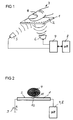
- the device has a sensor element 1 (FIG. 1), on the bearing surface 2 of which a test object 3, such as a human finger 4 or the whole hand is placed.
- the finger 4 is irradiated with broadband ultrasound via a transmission unit 5.
- the ultrasound signals at least partially penetrate into the interior of the finger 4 and / or are scattered or reflected on the - inner or outer - skin tissue structure.
- the scattered and reflected signals are received by a receiving unit 6.
- the transmitting unit 5 and the receiving unit 6 are controlled by a control unit 7, which forwards the signals to an evaluation unit 8, where the signals are evaluated according to known mathematical methods or methods.
- Patterns for biometric structures of authorized users are already stored in the evaluation unit 8.
- the received and evaluated signals are compared with the saved patterns. If there is at least a broad match, an enable signal is generated which is sent to a security unit and by which this is controlled from a locked to an unlocked state or vice versa.
- the release signal enables access to an object (for example by unlocking door locks) or the use of an object (for example by releasing a computer or a telephone).
- the identification device according to the invention is used in devices which obtain their energy from an energy source with a limited energy supply, there is a risk of this energy source being discharged.
- Batteries, accumulators, capacitors or functionally equivalent components can be used as the energy source.
- the word "battery” 9 for the sake of simplicity Energy source used the battery 9 supplies the connected components with a current and a voltage.
- the sensor element 1 has a switch 10 (FIG. 2).
- the switch 10 is arranged within the support surface 2 such that it switches when the finger 4 is touched or approached.
- the identification device is supplied with current by connecting the positive pole of the battery 9 to the voltage or power supply connections of the control unit 7 and the evaluation unit 8.
- the switch 10 can be designed as a pushbutton switch, which is depressed even with slight pressure on an elastic bulge 11 of the contact surface 2, so that the switch 10 is switched on.
- the switch 10 is located directly below the curvature 11, which is part of the cover layer of the sensor element 1. The switch 10 can therefore be actuated from the outside by the finger 4.
- the switch 10 should advantageously be designed as a micromechanical semiconductor switch.
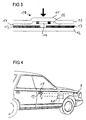
- two fixed, strip-shaped connecting electrodes 13 are arranged on a substrate 12 (FIG. 3), which are electrically connected to one another by a movable, ring-shaped switching electrode 14 when the switching electrode 14 is in electrical contact with the connecting electrodes 13.
- a soft-elastic curvature 11 is pressed down in a cover layer 15, the surface of which forms the support surface 2 (in the direction of the arrow in FIG. 3). Since the switching electrode 14 in the region of the curvature 11 on the Is attached underside of the cover layer 15, the switching electrode 14 is pressed onto the two connection electrodes 13 so that the electrical connection is made.
- the connection electrodes 13 and the switching electrode 14 are arranged in a cavity 16, the volume of which decreases when the curvature 11 is depressed.
- the cavity 16 is closed by an insulation layer 17 which is arranged between the cover layer 15 and the substrate 12 and the connection electrodes 13.
- connection electrodes 13 and the switching electrode 14 are made of an electrically conductive material and the other layers 12, 15 and 17 are made of an electrically insulating material.
- One of the connection electrodes 13 can be connected to the battery 9 and the other of the connection electrodes 13 to the control unit 7 and the evaluation unit 8.
- micromechanical semiconductor switches are known (for example from DE 44 14 970 A1) and therefore need not be explained in more detail.
- Known processes and materials (with silicon oxide as insulating layers and with aluminum alloys as electrically conductive layers) are also used in their manufacturing processes from IC production.
- the switch 10 can also be designed as a capacitive switch, one or more metallic electrodes of the capacitive switch 10 being arranged on or in the vicinity of the surface of the support surface 2.
- the capacitance of the switch 10 is changed, since the human finger or body has a capacitance and the skin has a dielectric constant.
- the switch 10 reacts to the change in capacitance (or also dielectric) and switches through.
- the switch 10 can also be designed as a piezo element, a voltage of which is known to be generated when it is actuated (mechanical pressure on the piezo element). As soon as the user presses the contact surface 2 with his finger 4, the piezo switch is actuated and a voltage is generated which can also be used to supply energy to the identification device.
- the identification device can also serve as an emergency device in the case of an empty battery 9. By actuating the switch 10 once or several times, such a high voltage is generated that is sufficient to supply the identification device with energy alone.
- the switch 10 it is not essential how the switch 10 is designed, but only that the switch 10 switches on the power supply of the identification device when a test object 3, 4 is guided in the vicinity of the identification device, touches the contact surface 2 or in the Contact surface 2 integrated switch 10 depresses.
- the identification process remains switched on as long as the test object 3, 4 lies on the support surface 2 or as long as the identification process lasts.
- the switch 10 must not particularly influence the identification, ie the detection of the characteristics of the test object 3, 4 (inner spatial structure of the skin, fingerprint, etc.). It should therefore have only very small dimensions or be made of a material which is well permeable to the signals emitted by the transmitter unit 5 and received by the receiver unit 6.
- the size of the switch 10 depends on the one hand on the size of the test object 3 and, on the other hand, on whether the signals received and not disturbed by the test object 3, 4 are sufficient to identify the test object 3 well and reliably.
- the identification device according to the invention can preferably be used in a motor vehicle.
- the sensor element 1 is arranged on or in the vicinity of a door handle 18 (FIG. 4). If the user places his finger 4 on the contact surface 2 of the sensor element 1, the identification device is supplied with current.
- the switch 10 switches an electrical connection between the positive pole of the motor vehicle battery 9 and the control unit 7 and the evaluation unit 8.
- a door lock 19 can be unlocked and / or the immobilizer released so that the motor vehicle is used, i.e. can be started and driven.
- the identification device can also be arranged inside the vehicle in order to release the immobilizer when authorized.
- the sensor element 1 is then arranged on an ignition button, not shown, which is to be operated like an ignition key when the engine is to be started.
- the immobilizer prevents the operation or use of the motor vehicle through coded intervention in at least one operationally relevant unit (such as the engine control, ignition control, fuel supply, transmission control, brake system, etc.).
- the immobilizer sharpens itself when leaving the motor vehicle.
- the immobilizer must be released again with the aid of an authentication. If access to the motor vehicle has already taken place via the biometric identification, the immobilizer can also be released via another authentication means, for example a transmitter / transponder that emits a user-specific code signal.
- control unit 7 and the evaluation unit 8 are advantageously in the vicinity of the sensor element 1 and optionally in arranged near the security unit. As a result, long lengths of line between the individual components are not required.
- the control unit 7 and the evaluation unit 8 can also be arranged within an already existing control unit in the motor vehicle.
- the transmitting unit 5 and the receiving unit 6 are then connected to the control unit via separate lines or via a motor vehicle bus line.
- the engine control unit can then serve as the control unit, in which case the immobilizer function is also implemented.
- the switch 10 can also be connected to a pyrotechnic element (such as a squib, such as is used, for example, to activate a gas generator to inflate an airbag of an airbag). If the energy supply of the motor vehicle battery is too low, the pyrotechnic element can be activated by the switch 10 and thus supply the energy for unlocking the door locks. The motor vehicle battery can then be recharged.
- a pyrotechnic element such as a squib, such as is used, for example, to activate a gas generator to inflate an airbag of an airbag.
- the switch 10 is implemented as a piezo element and there is an emergency situation (power / voltage failure, empty battery 9 or accident)
- the voltage generated by the piezo element can be used to ignite the pyrotechnic element in order to actuate door bolts of door locks.
- no identification may take place only in the event of an accident, since the authorized user is still in the vehicle in such an event. This is because auxiliary persons must be able to open the motor vehicle from the outside in an emergency.
- the identification process can proceed as described, for example, in the patent specifications DE 42 22 387 C2, US 4,977,601 or in the published patent application EP 0 402 779 A2.
- the measuring device can use light signals, sound signals or electromagnetic waves are operated.
- the surface structure of the epidermis can also be measured indirectly via an intermediate layer, as described in the patent specification DE 42 22 287.
- Other biometric characteristics of a user can also be recorded, such as sweat glands in a user's finger 4, dimensions or structure of the palm of the hand or functionally equivalent biometric structures.
- the method for measuring the surface structure of the test object 3, 4 or detecting the biometric structure of the test object 3, 4 is not relevant for the identification device according to the invention. It is important that the switch 10 is part of the support surface 2 or the sensor element 1 and that the switch 10 switches on the power supply for the identification device by placing or approaching the test object 3.
- the switch 10 should be arranged approximately in the middle of the support surface 2 so that it is actuated safely when the test object 3, 4 touches the support surface 2. However, several switches 10 can also be arranged distributed over the contact surface 2. However, these switches 10 must not strongly influence the identification process, i.e. the dimensions of each switch 10 should therefore be well below one millimeter or the switch 10 should be transparent to the signals used.
- the switch 10 is advantageously arranged within the support surface 2 in such a way that it least disturbs the identification process, but is operated reliably by the test object 3, 4.
- one or more additional electronic switching devices are provided which are activated by the switch 10 in order to establish the electrical connection between the battery 9 and the identification device.
- Switching devices a relay, a semiconductor circuit breaker or other functionally equivalent switches can be used.
- the switch 10 is the trigger for switching on the identification device and only allows current to flow to the identification device during the identification process.
- the transmission unit 5 can transmit broadband pulses, the impulse response of which is received by the reception unit 6.
- the transmitting unit 5 and the receiving unit 6 can also be formed in a matrix (areal) in order to generate a so-called hologram by parallel transmission and reception of signals, which is evaluated by the evaluation unit 8 and compared with the stored patterns.
- the transmitting unit 5 and the receiving unit 6 can also be arranged inside or directly on the sensor element 1.
- the sensor element 1 is plate-shaped, disk-shaped or also as a hollow body filled with a special transmission medium.
- the identification device according to the invention is not only limited to use in a motor vehicle. It can also be used with other devices, such as personal computers, telephones or other devices for which authorization is requested or authentication takes place.
- control unit 7 and the evaluation unit 8 can be realized by a single component, for example by a microprocessor.
- the microprocessor can be present in the device anyway and can therefore also control other functions.
Landscapes
- Engineering & Computer Science (AREA)
- Human Computer Interaction (AREA)
- Physics & Mathematics (AREA)
- General Physics & Mathematics (AREA)
- Multimedia (AREA)
- Theoretical Computer Science (AREA)
- Lock And Its Accessories (AREA)
Priority Applications (1)
| Application Number | Priority Date | Filing Date | Title |
|---|---|---|---|
| EP96106883A EP0805247A1 (fr) | 1996-04-30 | 1996-04-30 | Dispositif d'identification |
Applications Claiming Priority (1)
| Application Number | Priority Date | Filing Date | Title |
|---|---|---|---|
| EP96106883A EP0805247A1 (fr) | 1996-04-30 | 1996-04-30 | Dispositif d'identification |
Publications (1)
| Publication Number | Publication Date |
|---|---|
| EP0805247A1 true EP0805247A1 (fr) | 1997-11-05 |
Family
ID=8222736
Family Applications (1)
| Application Number | Title | Priority Date | Filing Date |
|---|---|---|---|
| EP96106883A Withdrawn EP0805247A1 (fr) | 1996-04-30 | 1996-04-30 | Dispositif d'identification |
Country Status (1)
| Country | Link |
|---|---|
| EP (1) | EP0805247A1 (fr) |
Cited By (24)
| Publication number | Priority date | Publication date | Assignee | Title |
|---|---|---|---|---|
| DE19821203C1 (de) * | 1998-05-12 | 1999-10-28 | Keso Gmbh Salzburg | Schließvorrichtung |
| EP0954098A3 (fr) * | 1998-04-03 | 1999-11-24 | Robert Bosch Gmbh | Système de détection et dispositif interrupteur |
| WO1999061731A1 (fr) * | 1998-05-27 | 1999-12-02 | Bayerische Motoren Werke Aktiengesellschaft | Dispositif de telecommande pour vehicules |
| WO2000022732A1 (fr) * | 1998-10-09 | 2000-04-20 | Eaton Corporation | Element d'actionnement pour un commutateur electrique |
| EP0976897A4 (fr) * | 1997-12-26 | 2000-10-11 | Enix Corp | Mecanisme de verrouillage et interrupteur faisant appel a un capteur dactyloscopique a pression |
| WO2001051743A1 (fr) * | 2000-01-13 | 2001-07-19 | Robert Bosch Gmbh | Procede et dispositif de demande d'autorisation dans une automobile |
| EP1050011A4 (fr) * | 1997-11-20 | 2002-01-09 | Quo Technologies Llc | Procede et systeme de reconnaissance biometrique dans lesquels on utilise des caracteristiques distinctives internes |
| WO2002037402A1 (fr) * | 2000-11-03 | 2002-05-10 | Stockburger, Andreas | Procede et dispositif pour identifier des objets a tester |
| US6522773B1 (en) * | 1998-03-03 | 2003-02-18 | Siemens Aktiengesellschaft | Fingertip sensor with integrated key switch |
| DE102004010554A1 (de) * | 2004-03-04 | 2005-09-22 | Cm Electronic Gmbh | Fingerabdruck-Aufnahmegerät |
| WO2005106163A1 (fr) * | 2004-04-22 | 2005-11-10 | Huf Hülsbeck & Fürst Gmbh & Co. Kg | Dispositif pour actionner un dispositif de fermeture electrique ou mecanique sur une porte et/ou un volet d'un vehicule |
| EP1411476A3 (fr) * | 2002-10-07 | 2006-02-08 | ASSA ABLOY Sicherheitstechnik GmbH | Dispositif de lecture pour l'identification de personnes autorisées |
| EP1404935A4 (fr) * | 2001-05-19 | 2006-05-03 | Keico Hightech Inc | Poignee de verrouillage de porte avec systeme de reconnaissance d'empreinte digitale |
| EP1395944A4 (fr) * | 2001-05-19 | 2006-05-03 | Keico Hightech Inc | Appareil de reconnaissance d'empreintes dote d'une fonction automatique de detection du contact d'un doigt |
| DE102004022946B4 (de) * | 2004-05-10 | 2007-05-16 | Robert Seuffer Gmbh & Co Kg | Kraftabhängige Tasteinrichtung zum Steuern eines einem Verbraucher zugeführten elektrischen Signals |
| FR2895007A1 (fr) * | 2005-12-16 | 2007-06-22 | Valeo Securite Habitacle Sas | Dispositif de detection et de communication avec un identifiant, equipant un ouvrant d'un vehicule |
| WO2007096304A1 (fr) * | 2006-02-20 | 2007-08-30 | Huf Hülsbeck & Fürst Gmbh & Co. Kg | Dispositif de commutation |
| EP1849644A1 (fr) * | 2006-04-26 | 2007-10-31 | Ford Global Technologies, LLC | Système et procédé pour l'activation sélective du moteur selon la capacité du conducteur |
| FR2907928A1 (fr) * | 2006-10-31 | 2008-05-02 | Somfy Soc Par Actions Simplifi | Dispositif autonome d'authentification par lecteur d'empreintes digitales |
| DE102007017818A1 (de) * | 2007-04-13 | 2008-10-16 | Cherry Gmbh | Fingerabdruck-Lesegerät |
| EP1786999A4 (fr) * | 2004-08-10 | 2009-07-29 | Magna Closures Inc | Dispositif a double verrouillage et deverouillage electrique |
| CN101327780B (zh) * | 2007-06-22 | 2011-12-28 | 霍弗·霍斯贝克及弗斯特两合公司 | 用于对设备进行启动的安全系统 |
| DE10048965B4 (de) * | 2000-03-28 | 2013-04-18 | Mitsubishi Denki K.K. | Tragbarer Sender für ein Fahrzeugschlüsselsystem |
| WO2019117696A1 (fr) * | 2017-12-11 | 2019-06-20 | Université Internationale de RABAT | Dispositif de sécurité antivol pour les véhicules à traction humaine |
Citations (7)
| Publication number | Priority date | Publication date | Assignee | Title |
|---|---|---|---|---|
| US3201961A (en) * | 1962-03-26 | 1965-08-24 | Finger Keys Inc | Control device |
| DE2501516A1 (de) * | 1975-01-16 | 1976-07-22 | Guenter Prumbaum | Fingerabdruck-sicherheitsaggregat |
| FR2500520A1 (fr) * | 1981-02-24 | 1982-08-27 | Thomson Csf | Dispositif de commande electromecanique d'une serrure |
| GB2185937A (en) * | 1986-01-11 | 1987-08-05 | Shea Michael Anthony O | Credit card |
| US4712393A (en) * | 1984-05-25 | 1987-12-15 | Fichet Bauche | Method and device for permanently locking a movable member in a framework |
| DE4016832A1 (de) * | 1990-05-25 | 1991-11-28 | Priesemuth W | Tuerverschlusseinrichtung |
| EP0582969A1 (fr) * | 1992-08-11 | 1994-02-16 | SMH Management Services AG | Dispositif de sécurité destiné à l'ouverture et/ou à la fermeture de portes notamment pour un véhicule automobile |
-
1996
- 1996-04-30 EP EP96106883A patent/EP0805247A1/fr not_active Withdrawn
Patent Citations (7)
| Publication number | Priority date | Publication date | Assignee | Title |
|---|---|---|---|---|
| US3201961A (en) * | 1962-03-26 | 1965-08-24 | Finger Keys Inc | Control device |
| DE2501516A1 (de) * | 1975-01-16 | 1976-07-22 | Guenter Prumbaum | Fingerabdruck-sicherheitsaggregat |
| FR2500520A1 (fr) * | 1981-02-24 | 1982-08-27 | Thomson Csf | Dispositif de commande electromecanique d'une serrure |
| US4712393A (en) * | 1984-05-25 | 1987-12-15 | Fichet Bauche | Method and device for permanently locking a movable member in a framework |
| GB2185937A (en) * | 1986-01-11 | 1987-08-05 | Shea Michael Anthony O | Credit card |
| DE4016832A1 (de) * | 1990-05-25 | 1991-11-28 | Priesemuth W | Tuerverschlusseinrichtung |
| EP0582969A1 (fr) * | 1992-08-11 | 1994-02-16 | SMH Management Services AG | Dispositif de sécurité destiné à l'ouverture et/ou à la fermeture de portes notamment pour un véhicule automobile |
Cited By (31)
| Publication number | Priority date | Publication date | Assignee | Title |
|---|---|---|---|---|
| EP1050011A4 (fr) * | 1997-11-20 | 2002-01-09 | Quo Technologies Llc | Procede et systeme de reconnaissance biometrique dans lesquels on utilise des caracteristiques distinctives internes |
| EP0976897A4 (fr) * | 1997-12-26 | 2000-10-11 | Enix Corp | Mecanisme de verrouillage et interrupteur faisant appel a un capteur dactyloscopique a pression |
| US6522773B1 (en) * | 1998-03-03 | 2003-02-18 | Siemens Aktiengesellschaft | Fingertip sensor with integrated key switch |
| RU2214165C2 (ru) * | 1998-03-03 | 2003-10-20 | Сименс Акциенгезелльшафт | Идентифицирующий отпечаток пальца датчик с интегрированным нажимным выключателем |
| EP0954098A3 (fr) * | 1998-04-03 | 1999-11-24 | Robert Bosch Gmbh | Système de détection et dispositif interrupteur |
| US6429782B2 (en) | 1998-04-03 | 2002-08-06 | Robert Bosch Gmbh | Detection system and switch device |
| DE19821203C1 (de) * | 1998-05-12 | 1999-10-28 | Keso Gmbh Salzburg | Schließvorrichtung |
| WO1999061731A1 (fr) * | 1998-05-27 | 1999-12-02 | Bayerische Motoren Werke Aktiengesellschaft | Dispositif de telecommande pour vehicules |
| US6924729B1 (en) | 1998-05-27 | 2005-08-02 | Bayerische Motoren Werke Aktiengesellschaft | Remote control device for motor vehicles |
| WO2000022732A1 (fr) * | 1998-10-09 | 2000-04-20 | Eaton Corporation | Element d'actionnement pour un commutateur electrique |
| WO2001051743A1 (fr) * | 2000-01-13 | 2001-07-19 | Robert Bosch Gmbh | Procede et dispositif de demande d'autorisation dans une automobile |
| DE10048965B4 (de) * | 2000-03-28 | 2013-04-18 | Mitsubishi Denki K.K. | Tragbarer Sender für ein Fahrzeugschlüsselsystem |
| WO2002037402A1 (fr) * | 2000-11-03 | 2002-05-10 | Stockburger, Andreas | Procede et dispositif pour identifier des objets a tester |
| EP1404935A4 (fr) * | 2001-05-19 | 2006-05-03 | Keico Hightech Inc | Poignee de verrouillage de porte avec systeme de reconnaissance d'empreinte digitale |
| EP1395944A4 (fr) * | 2001-05-19 | 2006-05-03 | Keico Hightech Inc | Appareil de reconnaissance d'empreintes dote d'une fonction automatique de detection du contact d'un doigt |
| EP1411476A3 (fr) * | 2002-10-07 | 2006-02-08 | ASSA ABLOY Sicherheitstechnik GmbH | Dispositif de lecture pour l'identification de personnes autorisées |
| DE102004010554A1 (de) * | 2004-03-04 | 2005-09-22 | Cm Electronic Gmbh | Fingerabdruck-Aufnahmegerät |
| JP2008501079A (ja) * | 2004-04-22 | 2008-01-17 | フフ・ヒユルスベツク・ウント・フユルスト・ゲゼルシヤフト・ミツト・ベシユレンクテル・ハフツング・ウント・コンパニー・コマンデイトゲゼルシヤフト | 車両の扉及び/又ははね上げ蓋にある電気又は電気−機械錠掛け装置を操作する装置 |
| WO2005106163A1 (fr) * | 2004-04-22 | 2005-11-10 | Huf Hülsbeck & Fürst Gmbh & Co. Kg | Dispositif pour actionner un dispositif de fermeture electrique ou mecanique sur une porte et/ou un volet d'un vehicule |
| DE102004022946B4 (de) * | 2004-05-10 | 2007-05-16 | Robert Seuffer Gmbh & Co Kg | Kraftabhängige Tasteinrichtung zum Steuern eines einem Verbraucher zugeführten elektrischen Signals |
| EP1786999A4 (fr) * | 2004-08-10 | 2009-07-29 | Magna Closures Inc | Dispositif a double verrouillage et deverouillage electrique |
| US7827836B2 (en) | 2004-08-10 | 2010-11-09 | Magna Closures Inc. | Power release double-locking latch |
| WO2007071838A3 (fr) * | 2005-12-16 | 2007-08-16 | Valeo Securite Habitacle | Dispositif de detection et de communication avec un identifiant, equipant un ouvrant d'un vehicule |
| FR2895007A1 (fr) * | 2005-12-16 | 2007-06-22 | Valeo Securite Habitacle Sas | Dispositif de detection et de communication avec un identifiant, equipant un ouvrant d'un vehicule |
| WO2007096304A1 (fr) * | 2006-02-20 | 2007-08-30 | Huf Hülsbeck & Fürst Gmbh & Co. Kg | Dispositif de commutation |
| CN101385049B (zh) * | 2006-02-20 | 2011-11-09 | 霍弗·霍斯贝克及弗斯特两合公司 | 开关装置 |
| EP1849644A1 (fr) * | 2006-04-26 | 2007-10-31 | Ford Global Technologies, LLC | Système et procédé pour l'activation sélective du moteur selon la capacité du conducteur |
| FR2907928A1 (fr) * | 2006-10-31 | 2008-05-02 | Somfy Soc Par Actions Simplifi | Dispositif autonome d'authentification par lecteur d'empreintes digitales |
| DE102007017818A1 (de) * | 2007-04-13 | 2008-10-16 | Cherry Gmbh | Fingerabdruck-Lesegerät |
| CN101327780B (zh) * | 2007-06-22 | 2011-12-28 | 霍弗·霍斯贝克及弗斯特两合公司 | 用于对设备进行启动的安全系统 |
| WO2019117696A1 (fr) * | 2017-12-11 | 2019-06-20 | Université Internationale de RABAT | Dispositif de sécurité antivol pour les véhicules à traction humaine |
Similar Documents
| Publication | Publication Date | Title |
|---|---|---|
| EP0805247A1 (fr) | Dispositif d'identification | |
| DE602004003947T2 (de) | Elektrisch betätigbare schliessanordnung für kraftfahrzeug | |
| EP1023511B1 (fr) | Dispositif de fermeture, en particulier pour vehicules automobiles | |
| EP2240882B1 (fr) | Dispositif de protection biométrique | |
| DE19839355C1 (de) | Fahrzeugsicherungssystem mit Keyless-Go-Funktionalität | |
| DE102006016737B4 (de) | Verfahren und Vorrichtung zum Konfigurieren verschiedener Betriebsmodi in einem passiven Schließsystem | |
| EP1235190B1 (fr) | Dispositif de commande et/ou de verrouillage sans clé | |
| DE19740523C2 (de) | Identifikationsvorrichtung | |
| DE102005059061B4 (de) | Verfahren und Vorrichtung zum Öffnen eines Fahrzeugs | |
| DE19729404C2 (de) | Sicherungseinrichtung gegen unbefugte Benutzung eines Kraftfahrzeugs und Verfahren zum Freigeben der Sicherungseinrichtung | |
| DE19938064B4 (de) | Identifikationsvorrichtung, insbesondere für die Zugangskontrolle zu einem Objekt | |
| DE19811872C1 (de) | Zündanlaßschalter für ein Kraftfahrzeug | |
| EP0954098A2 (fr) | Système de détection et dispositif interrupteur | |
| EP1038148A1 (fr) | Cran d'arret pour arme a feu portative | |
| WO2007003534A1 (fr) | Systeme de poignee | |
| WO2000043622A1 (fr) | Dispositif de controle d'acces sans cle pour des vehicules automobiles et procede pour effectuer un controle d'autorisation d'acces sans cle pour des vehicules automobiles | |
| WO1998035118A1 (fr) | Systeme d'identification | |
| DE69716742T2 (de) | Zugangs-kontrollvorrichtung für einen mit einer tür abgeschlossenen raum | |
| EP2098671B1 (fr) | Véhicule automobile doté d'une pièce de véhicule réglable automatiquement en position ouverte ou fermée | |
| WO2004063504A1 (fr) | Dispositif pour verrouiller et deverrouiller une porte de vehicule | |
| DE102022203459A1 (de) | Baugruppe eines Fahrzeugs mit einem an einer Fahrzeugtür angeordneten Bedienelement | |
| EP1510637A1 (fr) | Dispositif d'actionnement pour le systéme de verrouillage d'un véhicule automobile et procede pour indiquer les états de fonctionnements | |
| DE19957087B4 (de) | Kraftfahrzeug-Türschliesssystem | |
| EP1239420A1 (fr) | Système d'identification et transmetteur de code pour autorisation d'accès à un objet ou l'utilisation de cet objet, notamment un véhicule | |
| DE102005061754A1 (de) | Sensoranordnung zum Erfassen des Andrückens eines Bedienerkörperteils an eine Sensorfläche |
Legal Events
| Date | Code | Title | Description |
|---|---|---|---|
| PUAI | Public reference made under article 153(3) epc to a published international application that has entered the european phase |
Free format text: ORIGINAL CODE: 0009012 |
|
| AK | Designated contracting states |
Kind code of ref document: A1 Designated state(s): DE FR GB |
|
| 17P | Request for examination filed |
Effective date: 19971120 |
|
| RBV | Designated contracting states (corrected) |
Designated state(s): DE FR GB |
|
| STAA | Information on the status of an ep patent application or granted ep patent |
Free format text: STATUS: THE APPLICATION IS DEEMED TO BE WITHDRAWN |
|
| 18D | Application deemed to be withdrawn |
Effective date: 19991103 |