EP0805251A2 - Arrêt de porte pour véhicule - Google Patents
Arrêt de porte pour véhicule Download PDFInfo
- Publication number
- EP0805251A2 EP0805251A2 EP97102828A EP97102828A EP0805251A2 EP 0805251 A2 EP0805251 A2 EP 0805251A2 EP 97102828 A EP97102828 A EP 97102828A EP 97102828 A EP97102828 A EP 97102828A EP 0805251 A2 EP0805251 A2 EP 0805251A2
- Authority
- EP
- European Patent Office
- Prior art keywords
- housing
- holder according
- door
- frame
- door holder
- Prior art date
- Legal status (The legal status is an assumption and is not a legal conclusion. Google has not performed a legal analysis and makes no representation as to the accuracy of the status listed.)
- Granted
Links
Images
Classifications
-
- E—FIXED CONSTRUCTIONS
- E05—LOCKS; KEYS; WINDOW OR DOOR FITTINGS; SAFES
- E05C—BOLTS OR FASTENING DEVICES FOR WINGS, SPECIALLY FOR DOORS OR WINDOWS
- E05C17/00—Devices for holding wings open; Devices for limiting opening of wings or for holding wings open by a movable member extending between frame and wing; Braking devices, stops or buffers, combined therewith
- E05C17/02—Devices for holding wings open; Devices for limiting opening of wings or for holding wings open by a movable member extending between frame and wing; Braking devices, stops or buffers, combined therewith by mechanical means
- E05C17/04—Devices for holding wings open; Devices for limiting opening of wings or for holding wings open by a movable member extending between frame and wing; Braking devices, stops or buffers, combined therewith by mechanical means with a movable bar or equivalent member extending between frame and wing
- E05C17/12—Devices for holding wings open; Devices for limiting opening of wings or for holding wings open by a movable member extending between frame and wing; Braking devices, stops or buffers, combined therewith by mechanical means with a movable bar or equivalent member extending between frame and wing consisting of a single rod
- E05C17/20—Devices for holding wings open; Devices for limiting opening of wings or for holding wings open by a movable member extending between frame and wing; Braking devices, stops or buffers, combined therewith by mechanical means with a movable bar or equivalent member extending between frame and wing consisting of a single rod sliding through a guide
- E05C17/203—Devices for holding wings open; Devices for limiting opening of wings or for holding wings open by a movable member extending between frame and wing; Braking devices, stops or buffers, combined therewith by mechanical means with a movable bar or equivalent member extending between frame and wing consisting of a single rod sliding through a guide concealed, e.g. for vehicles
Definitions
- the present invention relates to a door holder for vehicle doors, with a door holding strap which can be pivotally attached to a vehicle spar and a holder housing to be fastened on the door side, the holding strap being guided through the holder housing with relative movement in its longitudinal direction and having a stop element at its free end, which in an extended end stop position comes to rest on the holder housing, so that a tensile force occurring is absorbed by the holder housing.
- the bracket housing consists of sheet steel, namely from a trough-shaped sheet metal part and a sheet metal cover part.
- the bracket housing With such a housing, it is quite simple and unproblematic to achieve a high level of stability for absorbing the pulling force which occurs in the extended end stop position (corresponds to the door opened all the way to the stop), which can be extraordinarily high in a pulse when the door is opened quickly and suddenly; this must be coped with by the holder housing without significant deformation.
- the relatively high weight of the known door holder is disadvantageous.
- the present invention is therefore based on the object of creating a door holder of the generic type which is distinguished by a low weight while at the same time complying with the usually specified specifications or functional regulations - in particular with regard to the tensile force-related resistance to deformation of the holder housing.
- high process reliability and low noise should be achieved.
- the size, in particular with regard to the necessary installation volume in the vehicle door should remain essentially unchanged, in any case not increase.
- the holder housing is designed as a composite of plastic and metal parts in such a way that the one occurring in the end stop position Tractive force is absorbed proportionately by the plastic and metal parts. According to the invention, it is therefore a combined plastic / metal housing with a “non-positive connection” or “force distribution” in the pulling direction (door opening direction).
- the holder housing consists of an inner housing made of plastic and a housing frame surrounding the inner housing made of metal.
- the inner housing mainly serves to accommodate spring-loaded latching elements which cooperate with latching depressions of the tether during its longitudinal movement in such a way that certain opening positions of the vehicle door are defined as "preferred positions".
- the plastic inner housing according to the invention can advantageously be manufactured with higher accuracy and dimensional accuracy, i.e. with higher process reliability compared to pure sheet metal housings. This results in a slight movement play of the functional parts, in particular the latching elements, whereby noise is effectively avoided.
- the plastic material advantageously has a noise-dampening effect anyway.
- the housing frame enclosing the inner housing in the pulling direction of the tether ensures, in combination or in the "combination of forces" with the inner housing, a very good deformation stability of the holder housing as a whole, so that the relevant functional regulations can be sufficiently fulfilled.
- the door holder according to the invention has the relevant specifications in a wide temperature range from -40 ° C to + 85 ° C, despite the use of plastic material, which is regarded as an unpredictable, surprising effect, because plastics are usually subject to strong (mechanical) changes in such wide temperature ranges.
- the inner housing is free, i.e. walls not covered by the housing frame have such stiffening ribs that the force acting in the pulling direction is distributed essentially uniformly over the length or width of the housing. This measure effectively counteracts bending or buckling deformations, advantageously both at low and at higher temperatures.
- the housing frame can be manufactured in a very simple manner from a sheet metal strip material or from strip steel; it preferably consists of two frame parts, which can have high dimensional stability, preferably by stiffening beads. This is advantageous for absorbing the tensile force of the tether in the fully assembled and installed state; However, there is the additional advantage that deformations of the frame parts are avoided even during the rough production before the one-part assembly of the door holder, if these are loosely accommodated in transport containers, for example.
- the frame parts of the housing frame are preferably rigidly connected to one another by means of stamped connections.
- connection known per se in sheet metal connections, also called “tox connection” is characterized in that the sheets lying flat one on top of the other without additional connector elements of the type of Thermoforming technology are “riveted” together.
- This technique is particularly advantageous for the present application because, on the one hand, the sheet metal material can be surface-treated, in particular galvanized, before the assembly connection, so that a welded connection would not be possible. On the other hand, practically no heating occurs with this type of connection, which could endanger the plastic inner housing.
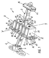
- a door holder 1 consists on the one hand of a rigid, rod-like or strip-like door retaining band 2, which can be articulated at one end to a vehicle spar, not shown, via a pivot bearing 4, so that the retaining band 2 is thus pivotable about a pivot axis 6.
- the door holder 1 has a holder housing 8 to be fastened on the door side, through which the holding band 2 is guided with relative movement in its longitudinal direction and interacts with its spring-loaded latching elements 10 arranged within the holder housing 8 during its longitudinal movement.
- the tether has corresponding locking recesses 12, which are arranged distributed over its length such that in cooperation with the locking elements 10 different opening positions of the vehicle door are defined as preferred positions.
- the details of this locking means are not the subject of the present invention and are therefore not explained in detail.
- the retaining strap 2 At its free end, which is opposite the pivot bearing 4 and is passed through the holder housing 8, the retaining strap 2 has a stop element 14 which, in an extended end stop position corresponding to the fully open position of the vehicle door, comes to rest on the holder housing 8, so that an occurring Tensile force F is absorbed by the holder housing 8.
- the door holder 1 is installed in a vehicle such that the longitudinal direction of the tether 2 and its direction of movement corresponds essentially to the direction of the vehicle longitudinal axis XX.
- the direction of action of the spring-loaded locking elements 10 corresponds to the vehicle vertical axis ZZ.
- the third coordinate direction corresponding to the transverse axis YY of the vehicle is also illustrated in the drawing.
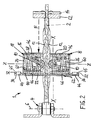
- the holding housing is designed as a composite of plastic and metal parts in such a way that the tensile force F is absorbed proportionately by the plastic and metal parts.
- the holder housing 8 expediently consists of an inner housing 16 made of plastic and a housing frame 18 which frames the inner housing 16 in such a way that a frame center plane coincides with the plane defined by the coordinate axes X-X and Z-Z.
- the inner housing 16 is not enclosed by the housing frame 18 in the direction of the Y-Y axis.
- the housing frame 18 consists essentially of two support sections 20, 22 which hold the inner housing 16 between them, as seen in the direction of the axis XX, and two side sections 24, 26 which connect the support sections 20, 22 and which connect the inner housing 16 in the direction of the ZZ axis.
- the support sections 20, 22 each have a through opening 28, 30, through which the retaining band 2 extends.
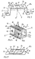
- the housing frame 18 is expediently formed rectangular from sheet metal strip material or steel strip sections. It consists of a first, essentially rectangular C-shaped frame part 18a (see FIG. 3) and a second, essentially tab-shaped frame part 18b (see Fig. 5).
- the first frame part 18a forms the first support section 20 and the two side sections 24, 26 and engages with these sections around the inner housing 16 up to its opposite side.
- the second frame part 18b is connected on this side to the first frame part 18a for the purpose of enclosing the inner housing and thus forms the second support section 22.
- the two frame parts 18a, 18b of the housing frame 18 each have two connecting lugs 32, 34 which extend away from one another in opposite directions.
- the two frame parts 18a, b are connected in a non-detachable manner via their connecting tabs 32, 34 which lie flat against one another in pairs, preferably by means of stamped connections 36 (so-called “tox connections”).
- the connecting straps 32 of the first frame part 18a are angled outward from the side sections 24, 26.
- the connecting tabs 34 of the second frame part 18b are formed as extensions of the support section 22.
- the housing frame 18 has stiffening beads 38, 40, at least in the region of the two support sections 20, 22.
- the support section 20 of the first frame part 18a facing the stop element 14 of the retaining band 2 has in its longitudinal edge regions one, ie at least two, line or groove-shaped stiffening beads 38 running essentially parallel to one another from the one side section 24 to the other side section 26.
- the other support section 22 of the second frame part 18b, which faces the end of the tether 2 on the vehicle side, preferably has an outer side facing away from the inner housing 16 stiffening bead 40 formed as a flat, in particular rectangular depression.
- the passage opening 30 is arranged within the surface area of this stiffening bead 40.
- a surface seal 42 (see FIG. 2) is arranged within the recessed stiffening bead 40, which is fixed, for example glued, in the stiffening bead 40.
- the retaining band 2 passes through the surface seal 42 in a sealing manner so that its longitudinal mobility is retained, but the through opening 30 is essentially sealed against dirt and moisture and the like.
- the housing frame 18 has fastening openings 44 in the region of the connecting straps 32, 34 for fastening the holder housing 8 on the door side.
- These fastening openings 44 are preferably designed as threaded holes which are rolled through openings in the two adjacent connecting plates 32, 34, which means that a non-cutting thread formation by rollers takes place only after the connecting plates 32, 34 have been connected. This is particularly advantageous because it achieves a large thread length for absorbing the forces acting in the joining direction, especially when - as shown - at least one of the two connecting lugs 32, 34 (here specifically 32) each has a stamped, hollow cylindrical one , the opening extending web shoulder 45.
- the thread rolling has the advantage that damage or even destruction of the surface corrosion protection already present (in particular galvanization) is largely excluded; the usual thread cutting would cause problems here. Finally, there is the advantageous "side effect" that the non-cutting thread forming it is also avoided that chips could get into the inner region of the inner housing 16.
- the inner housing 16 is held in the housing frame 18 without play in the direction of action of the tensile force F (axis X-X). The same applies in the direction of the Z-Z axis. Transverse to the direction of action of the tensile force F, i.e. In the direction of the third coordinate axis Y-Y, the inner housing 16 is held in the housing frame 18 via positive locking connections.
- the inner housing 16 has, at least in its area covered by the first support section 20, preferably also in the area of the second support section 22, projections 46 which engage in correspondingly arranged openings 48 of the housing frame 18 essentially without play.
- the inner housing 16 is preferably essentially cuboid with four housing walls 50a to d, which are adjacent to one another and thus form a kind of square tube, and two opposite open sides 52.
- the housing frame 18 thus encloses the inner housing 16 in the region of two opposite housing walls 50a, 50b and over the open sides 52.
- the two housing walls 50a, b mentioned have lead-through openings 54 which are penetrated by the retaining band 2. Accordingly, the feed-through openings 54 are essentially aligned with the feed-through openings 28, 30 of the housing frame 18. This can be clearly seen in FIG. 2.
- the inner housing 16 is stiffened in such a way that the stop element 14 is first inserted into the first support section 20 of the Housing frame 18 introduced tensile force F is passed proportionally via the inner housing 16 to the second support section 22, and preferably in a substantially uniform force distribution over the length (extension in the direction of the axis ZZ) of the second support section 22. 1 and 4, for this purpose the inner housing 16 has stiffening ribs 56 on each of its housing walls 50c, 50d, which are "released" from the housing frame 18 and extend between the support sections 20, 22 and which, starting from the housing wall 50a facing the first support section 20, in the direction of the housing wall 50b facing the second support section 22 and preferably end there in a support web 58.
- Each support web 58 runs along the corner edge of the inner housing 16 formed between the housing wall 50b and the adjacent housing wall 50c or 50d.
- the support webs 58 also encompass the second support section 22, which provides an additional positive connection between the inner housing 16 and the housing frame 18 in Direction of the axis YY causes.
- the locking elements 10 arranged inside the inner housing 16 are supported on the housing frame 18 via spring elements 60, in that the spring elements 60 bear in the direction of the open sides 52 of the inner housing 16 on the side sections 24, 26 of the housing frame 18 closing these sides 52.
- a material that is particularly suitable for the inner housing 16 is a fiber-reinforced — preferably glass-fiber-reinforced — plastic, in particular polyamide.
- a preferred material has the short name PA6GF30.
- the housing frame 18 consists of sheet steel (strip steel) with a preferably corrosion-protected, in particular galvanized surface. It can advantageously be a brightly galvanized and (yellow) chromated material with a surface layer thickness of about 10 ⁇ m.
- a preferred material has the short name St4K35-40GBK.
- the stop element 14 preferably carries on its side facing the holder housing 8 a damping element 62 made of an elastically deformable material.
- the size of the stop element 14 and possibly the damping element 62 is chosen such that a large-area contact with the holder housing 8 is ensured. "Large-area” means above all a large extension in the direction of the Z-Z axis.
- the invention is not limited to the exemplary embodiments shown and described, but also encompasses all embodiments having the same effect in the sense of the invention. Furthermore, the invention has not yet been limited to the combination of features defined in claim 1, but can also be defined by any other combination of specific features of all the individual features disclosed in total. This means that in principle practically every single feature of claim 1 can be omitted or replaced by at least one single feature disclosed elsewhere in the application. In this respect, claim 1 is only to be understood as a first attempt at formulation for an invention.
Landscapes
- Engineering & Computer Science (AREA)
- Mechanical Engineering (AREA)
- Lock And Its Accessories (AREA)
- Vehicle Step Arrangements And Article Storage (AREA)
- Support Devices For Sliding Doors (AREA)
Applications Claiming Priority (2)
| Application Number | Priority Date | Filing Date | Title |
|---|---|---|---|
| DE29606304U | 1996-04-05 | ||
| DE29606304U DE29606304U1 (de) | 1996-04-05 | 1996-04-05 | Türhalter für Fahrzeugtüren |
Publications (3)
| Publication Number | Publication Date |
|---|---|
| EP0805251A2 true EP0805251A2 (fr) | 1997-11-05 |
| EP0805251A3 EP0805251A3 (fr) | 1999-08-11 |
| EP0805251B1 EP0805251B1 (fr) | 2005-07-27 |
Family
ID=8022219
Family Applications (1)
| Application Number | Title | Priority Date | Filing Date |
|---|---|---|---|
| EP97102828A Expired - Lifetime EP0805251B1 (fr) | 1996-04-05 | 1997-02-21 | Arrêt de porte pour véhicule |
Country Status (3)
| Country | Link |
|---|---|
| EP (1) | EP0805251B1 (fr) |
| DE (2) | DE29606304U1 (fr) |
| ES (1) | ES2110938T3 (fr) |
Cited By (5)
| Publication number | Priority date | Publication date | Assignee | Title |
|---|---|---|---|---|
| WO2006000536A1 (fr) * | 2004-06-23 | 2006-01-05 | Friedr. Fingscheidt Gmbh | Element de retenue pour porte de vehicule a moteur |
| EP2011940A1 (fr) * | 2007-07-02 | 2009-01-07 | Gammastamp S.p.A. | Dispositif d'arrêt de porte pour véhicules |
| US7530141B2 (en) | 2003-01-22 | 2009-05-12 | Edscha Ag | Door arrester |
| US8429793B2 (en) | 2003-01-22 | 2013-04-30 | Edscha Ag | Door check |
| US9346341B2 (en) | 2014-06-06 | 2016-05-24 | Dr. Ing. H.C.F. Porsche Aktiengesellschaft | Door stop |
Families Citing this family (4)
| Publication number | Priority date | Publication date | Assignee | Title |
|---|---|---|---|---|
| DE19632630C2 (de) * | 1996-08-13 | 1998-09-10 | Bayerische Motoren Werke Ag | Feststellvorrichtung für eine Tür oder eine Klappe eines Kraftfahrzeugs |
| DE10347323B4 (de) * | 2003-10-08 | 2013-10-31 | Volkswagen Ag | Vorrichtung zur Feststellung einer Tür, Klappe oder dergleichen an einem Kraftfahrzeug |
| DE102010051250A1 (de) * | 2010-11-12 | 2012-05-16 | Gm Global Technology Operations Llc (N.D.Ges.D. Staates Delaware) | Vorrichtung zum Feststellen eines bewegbaren plattenförmigen Körpers |
| DE102010051257A1 (de) * | 2010-11-12 | 2012-05-16 | Gm Global Technology Operations Llc (N.D.Ges.D. Staates Delaware) | Vorrichtung zum Feststellen eines bewegbaren plattenförmigen Körpers |
Family Cites Families (7)
| Publication number | Priority date | Publication date | Assignee | Title |
|---|---|---|---|---|
| JPH0423171Y2 (fr) * | 1986-09-30 | 1992-05-28 | ||
| FR2679287B1 (fr) * | 1991-07-15 | 1995-11-10 | Etude Develop Indl Technologiq | Tirant pour dispositif d'arret de porte de type frottant et dispositif d'arret de porte comportant ce tirant. |
| GB9203601D0 (en) * | 1992-02-20 | 1992-04-08 | Bloxwich Eng | Door checks for vehicles |
| DE4330828A1 (de) * | 1993-09-11 | 1995-03-16 | Fingscheidt Gmbh Friedr | Türhalter für Fahrzeugtüren |
| DE9417883U1 (de) * | 1994-11-08 | 1996-03-07 | Ed. Scharwächter GmbH + Co KG, 42855 Remscheid | Kraftwagentürfeststeller |
| DE9419099U1 (de) * | 1994-11-29 | 1995-03-23 | Behm, Ernst, 42477 Radevormwald | Türfeststeller für Kfz-Türen |
| DE29611819U1 (de) * | 1996-07-06 | 1996-09-05 | Friedr. Fingscheidt GmbH, 42551 Velbert | Rastvorrichtung insbesondere für Fahrzeug-Türhalter |
-
1996
- 1996-04-05 DE DE29606304U patent/DE29606304U1/de not_active Expired - Lifetime
-
1997
- 1997-02-21 ES ES97102828T patent/ES2110938T3/es not_active Expired - Lifetime
- 1997-02-21 EP EP97102828A patent/EP0805251B1/fr not_active Expired - Lifetime
- 1997-02-21 DE DE59712377T patent/DE59712377D1/de not_active Expired - Lifetime
Cited By (5)
| Publication number | Priority date | Publication date | Assignee | Title |
|---|---|---|---|---|
| US7530141B2 (en) | 2003-01-22 | 2009-05-12 | Edscha Ag | Door arrester |
| US8429793B2 (en) | 2003-01-22 | 2013-04-30 | Edscha Ag | Door check |
| WO2006000536A1 (fr) * | 2004-06-23 | 2006-01-05 | Friedr. Fingscheidt Gmbh | Element de retenue pour porte de vehicule a moteur |
| EP2011940A1 (fr) * | 2007-07-02 | 2009-01-07 | Gammastamp S.p.A. | Dispositif d'arrêt de porte pour véhicules |
| US9346341B2 (en) | 2014-06-06 | 2016-05-24 | Dr. Ing. H.C.F. Porsche Aktiengesellschaft | Door stop |
Also Published As
| Publication number | Publication date |
|---|---|
| ES2110938T3 (es) | 2006-02-16 |
| DE59712377D1 (de) | 2005-09-01 |
| EP0805251B1 (fr) | 2005-07-27 |
| EP0805251A3 (fr) | 1999-08-11 |
| ES2110938T1 (es) | 1998-03-01 |
| DE29606304U1 (de) | 1996-06-27 |
Similar Documents
| Publication | Publication Date | Title |
|---|---|---|
| DE69309699T3 (de) | Sicherheitsbalken | |
| EP0749378B1 (fr) | Raclette d'essuie-glace | |
| EP1840010B1 (fr) | Structure portante pour un véhicule automobile | |
| EP3504391A1 (fr) | Ensemble charnière pour un boîtier d'armoire de distribution et boîtier d'armoire de distribution correspondant | |
| EP0805251A2 (fr) | Arrêt de porte pour véhicule | |
| EP0643184B1 (fr) | Dispositif de retenue de portes de véhicules automobiles | |
| EP4339036B1 (fr) | Véhicule automobile avec agencement de pare-chocs | |
| DE102008035389A1 (de) | Drehfalle mit Schließbolzenaufnahme | |
| DE102019104439A1 (de) | Anschlussgelenkanordnung zum Anschluss einer längenverstellbaren Antriebsanordnung an ein Kraftfahrzeug | |
| EP2956331B1 (fr) | Siège de véhicule avec unité de verrouillage | |
| DE102016107048B4 (de) | Rahmeneinheit | |
| DE102013202547A1 (de) | Gurtaufrollerrahmen | |
| DE102024125190A1 (de) | Verbesserte befestigungsklammer | |
| EP3665038B1 (fr) | Mecanisme de reglage longitudinal pour un siege de vehicule | |
| DE3328798C2 (fr) | ||
| DE3606812A1 (de) | Verkleidung fuer einen einstiegsschweller eines kraftfahrzeugs | |
| DE10046717A1 (de) | Schließvorrichtung für eine Fahrzeugtür | |
| DE2850470C2 (de) | Zu öffnende Klappe, insbesondere Tankklappe | |
| DE102006020044B4 (de) | Befestigung eines Türgriffs | |
| DE102020103627B4 (de) | Federstiftstossverbinder | |
| DE102013000264A1 (de) | Kraftfahrzeug-Diebstahlsicherungsrahmen | |
| DE102009042633B9 (de) | Kraftfahrzeug mit Crashbox | |
| DE3120065A1 (de) | Moebelscharnier | |
| DE20306882U1 (de) | Mitnehmer für Seilzug-Fensterheber für eine Fensterscheibe eines Kraftfahrzeuges | |
| DE4301053C1 (de) | Schutzabdeckung für ein Türschloß in einer Seitentür eines Kraftfahrzeugs |
Legal Events
| Date | Code | Title | Description |
|---|---|---|---|
| PUAI | Public reference made under article 153(3) epc to a published international application that has entered the european phase |
Free format text: ORIGINAL CODE: 0009012 |
|
| AK | Designated contracting states |
Kind code of ref document: A2 Designated state(s): DE ES FR GB IT SE |
|
| ITCL | It: translation for ep claims filed |
Representative=s name: ING. A. GIAMBROCONO & C. S.R.L. |
|
| EL | Fr: translation of claims filed | ||
| GBC | Gb: translation of claims filed (gb section 78(7)/1977) | ||
| REG | Reference to a national code |
Ref country code: ES Ref legal event code: BA2A Ref document number: 2110938 Country of ref document: ES Kind code of ref document: T1 |
|
| PUAL | Search report despatched |
Free format text: ORIGINAL CODE: 0009013 |
|
| AK | Designated contracting states |
Kind code of ref document: A3 Designated state(s): DE ES FR GB IT SE |
|
| 17P | Request for examination filed |
Effective date: 19991113 |
|
| RAP1 | Party data changed (applicant data changed or rights of an application transferred) |
Owner name: DAIMLERCHRYSLER AG Owner name: FRIEDR. FINGSCHEIDT GMBH |
|
| 17Q | First examination report despatched |
Effective date: 20021105 |
|
| GRAP | Despatch of communication of intention to grant a patent |
Free format text: ORIGINAL CODE: EPIDOSNIGR1 |
|
| GRAS | Grant fee paid |
Free format text: ORIGINAL CODE: EPIDOSNIGR3 |
|
| GRAA | (expected) grant |
Free format text: ORIGINAL CODE: 0009210 |
|
| AK | Designated contracting states |
Kind code of ref document: B1 Designated state(s): DE ES FR GB IT SE |
|
| REG | Reference to a national code |
Ref country code: GB Ref legal event code: FG4D Free format text: NOT ENGLISH |
|
| REF | Corresponds to: |
Ref document number: 59712377 Country of ref document: DE Date of ref document: 20050901 Kind code of ref document: P |
|
| REG | Reference to a national code |
Ref country code: SE Ref legal event code: TRGR |
|
| GBT | Gb: translation of ep patent filed (gb section 77(6)(a)/1977) |
Effective date: 20051101 |
|
| REG | Reference to a national code |
Ref country code: SE Ref legal event code: RPOT |
|
| PGFP | Annual fee paid to national office [announced via postgrant information from national office to epo] |
Ref country code: FR Payment date: 20060125 Year of fee payment: 10 |
|
| PGFP | Annual fee paid to national office [announced via postgrant information from national office to epo] |
Ref country code: SE Payment date: 20060210 Year of fee payment: 10 |
|
| PGFP | Annual fee paid to national office [announced via postgrant information from national office to epo] |
Ref country code: ES Payment date: 20060214 Year of fee payment: 10 |
|
| REG | Reference to a national code |
Ref country code: ES Ref legal event code: FG2A Ref document number: 2110938 Country of ref document: ES Kind code of ref document: T3 |
|
| PGFP | Annual fee paid to national office [announced via postgrant information from national office to epo] |
Ref country code: IT Payment date: 20060228 Year of fee payment: 10 |
|
| ET | Fr: translation filed | ||
| PLBE | No opposition filed within time limit |
Free format text: ORIGINAL CODE: 0009261 |
|
| STAA | Information on the status of an ep patent application or granted ep patent |
Free format text: STATUS: NO OPPOSITION FILED WITHIN TIME LIMIT |
|
| 26N | No opposition filed |
Effective date: 20060428 |
|
| PG25 | Lapsed in a contracting state [announced via postgrant information from national office to epo] |
Ref country code: SE Free format text: LAPSE BECAUSE OF NON-PAYMENT OF DUE FEES Effective date: 20070222 |
|
| EUG | Se: european patent has lapsed | ||
| GBPC | Gb: european patent ceased through non-payment of renewal fee |
Effective date: 20070221 |
|
| REG | Reference to a national code |
Ref country code: FR Ref legal event code: ST Effective date: 20071030 |
|
| PG25 | Lapsed in a contracting state [announced via postgrant information from national office to epo] |
Ref country code: GB Free format text: LAPSE BECAUSE OF NON-PAYMENT OF DUE FEES Effective date: 20070221 Ref country code: FR Free format text: LAPSE BECAUSE OF NON-PAYMENT OF DUE FEES Effective date: 20070228 |
|
| REG | Reference to a national code |
Ref country code: ES Ref legal event code: FD2A Effective date: 20070222 |
|
| PG25 | Lapsed in a contracting state [announced via postgrant information from national office to epo] |
Ref country code: ES Free format text: LAPSE BECAUSE OF NON-PAYMENT OF DUE FEES Effective date: 20070222 |
|
| PGFP | Annual fee paid to national office [announced via postgrant information from national office to epo] |
Ref country code: GB Payment date: 20060215 Year of fee payment: 10 |
|
| PG25 | Lapsed in a contracting state [announced via postgrant information from national office to epo] |
Ref country code: IT Free format text: LAPSE BECAUSE OF NON-PAYMENT OF DUE FEES Effective date: 20070221 |
|
| PGFP | Annual fee paid to national office [announced via postgrant information from national office to epo] |
Ref country code: DE Payment date: 20120427 Year of fee payment: 16 |
|
| REG | Reference to a national code |
Ref country code: DE Ref legal event code: R119 Ref document number: 59712377 Country of ref document: DE Effective date: 20130903 |
|
| PG25 | Lapsed in a contracting state [announced via postgrant information from national office to epo] |
Ref country code: DE Free format text: LAPSE BECAUSE OF NON-PAYMENT OF DUE FEES Effective date: 20130903 |