EP0805320B1 - Kühlschrank mit eine rotierende Luftführungsklappe aufweisendem Kühlfach und Verfahren zur dessen Herstellung - Google Patents
Kühlschrank mit eine rotierende Luftführungsklappe aufweisendem Kühlfach und Verfahren zur dessen Herstellung Download PDFInfo
- Publication number
- EP0805320B1 EP0805320B1 EP97302954A EP97302954A EP0805320B1 EP 0805320 B1 EP0805320 B1 EP 0805320B1 EP 97302954 A EP97302954 A EP 97302954A EP 97302954 A EP97302954 A EP 97302954A EP 0805320 B1 EP0805320 B1 EP 0805320B1
- Authority
- EP
- European Patent Office
- Prior art keywords
- fuzzy
- evaporator
- compartment
- refrigerator
- rotary blade
- Prior art date
- Legal status (The legal status is an assumption and is not a legal conclusion. Google has not performed a legal analysis and makes no representation as to the accuracy of the status listed.)
- Expired - Lifetime
Links
Images


Classifications
-
- F—MECHANICAL ENGINEERING; LIGHTING; HEATING; WEAPONS; BLASTING
- F25—REFRIGERATION OR COOLING; COMBINED HEATING AND REFRIGERATION SYSTEMS; HEAT PUMP SYSTEMS; MANUFACTURE OR STORAGE OF ICE; LIQUEFACTION SOLIDIFICATION OF GASES
- F25D—REFRIGERATORS; COLD ROOMS; ICE-BOXES; COOLING OR FREEZING APPARATUS NOT OTHERWISE PROVIDED FOR
- F25D17/00—Arrangements for circulating cooling fluids; Arrangements for circulating gas, e.g. air, within refrigerated spaces
- F25D17/04—Arrangements for circulating cooling fluids; Arrangements for circulating gas, e.g. air, within refrigerated spaces for circulating air, e.g. by convection
- F25D17/06—Arrangements for circulating cooling fluids; Arrangements for circulating gas, e.g. air, within refrigerated spaces for circulating air, e.g. by convection by forced circulation
- F25D17/062—Arrangements for circulating cooling fluids; Arrangements for circulating gas, e.g. air, within refrigerated spaces for circulating air, e.g. by convection by forced circulation in household refrigerators
- F25D17/065—Arrangements for circulating cooling fluids; Arrangements for circulating gas, e.g. air, within refrigerated spaces for circulating air, e.g. by convection by forced circulation in household refrigerators with compartments at different temperatures
-
- F—MECHANICAL ENGINEERING; LIGHTING; HEATING; WEAPONS; BLASTING
- F25—REFRIGERATION OR COOLING; COMBINED HEATING AND REFRIGERATION SYSTEMS; HEAT PUMP SYSTEMS; MANUFACTURE OR STORAGE OF ICE; LIQUEFACTION SOLIDIFICATION OF GASES
- F25D—REFRIGERATORS; COLD ROOMS; ICE-BOXES; COOLING OR FREEZING APPARATUS NOT OTHERWISE PROVIDED FOR
- F25D17/00—Arrangements for circulating cooling fluids; Arrangements for circulating gas, e.g. air, within refrigerated spaces
- F25D17/04—Arrangements for circulating cooling fluids; Arrangements for circulating gas, e.g. air, within refrigerated spaces for circulating air, e.g. by convection
- F25D17/06—Arrangements for circulating cooling fluids; Arrangements for circulating gas, e.g. air, within refrigerated spaces for circulating air, e.g. by convection by forced circulation
- F25D17/08—Arrangements for circulating cooling fluids; Arrangements for circulating gas, e.g. air, within refrigerated spaces for circulating air, e.g. by convection by forced circulation using ducts
-
- F—MECHANICAL ENGINEERING; LIGHTING; HEATING; WEAPONS; BLASTING
- F25—REFRIGERATION OR COOLING; COMBINED HEATING AND REFRIGERATION SYSTEMS; HEAT PUMP SYSTEMS; MANUFACTURE OR STORAGE OF ICE; LIQUEFACTION SOLIDIFICATION OF GASES
- F25D—REFRIGERATORS; COLD ROOMS; ICE-BOXES; COOLING OR FREEZING APPARATUS NOT OTHERWISE PROVIDED FOR
- F25D2317/00—Details or arrangements for circulating cooling fluids; Details or arrangements for circulating gas, e.g. air, within refrigerated spaces, not provided for in other groups of this subclass
- F25D2317/06—Details or arrangements for circulating cooling fluids; Details or arrangements for circulating gas, e.g. air, within refrigerated spaces, not provided for in other groups of this subclass with forced air circulation
- F25D2317/065—Details or arrangements for circulating cooling fluids; Details or arrangements for circulating gas, e.g. air, within refrigerated spaces, not provided for in other groups of this subclass with forced air circulation characterised by the air return
- F25D2317/0653—Details or arrangements for circulating cooling fluids; Details or arrangements for circulating gas, e.g. air, within refrigerated spaces, not provided for in other groups of this subclass with forced air circulation characterised by the air return through the mullion
-
- F—MECHANICAL ENGINEERING; LIGHTING; HEATING; WEAPONS; BLASTING
- F25—REFRIGERATION OR COOLING; COMBINED HEATING AND REFRIGERATION SYSTEMS; HEAT PUMP SYSTEMS; MANUFACTURE OR STORAGE OF ICE; LIQUEFACTION SOLIDIFICATION OF GASES
- F25D—REFRIGERATORS; COLD ROOMS; ICE-BOXES; COOLING OR FREEZING APPARATUS NOT OTHERWISE PROVIDED FOR
- F25D2317/00—Details or arrangements for circulating cooling fluids; Details or arrangements for circulating gas, e.g. air, within refrigerated spaces, not provided for in other groups of this subclass
- F25D2317/06—Details or arrangements for circulating cooling fluids; Details or arrangements for circulating gas, e.g. air, within refrigerated spaces, not provided for in other groups of this subclass with forced air circulation
- F25D2317/067—Details or arrangements for circulating cooling fluids; Details or arrangements for circulating gas, e.g. air, within refrigerated spaces, not provided for in other groups of this subclass with forced air circulation characterised by air ducts
- F25D2317/0672—Outlet ducts
-
- F—MECHANICAL ENGINEERING; LIGHTING; HEATING; WEAPONS; BLASTING
- F25—REFRIGERATION OR COOLING; COMBINED HEATING AND REFRIGERATION SYSTEMS; HEAT PUMP SYSTEMS; MANUFACTURE OR STORAGE OF ICE; LIQUEFACTION SOLIDIFICATION OF GASES
- F25D—REFRIGERATORS; COLD ROOMS; ICE-BOXES; COOLING OR FREEZING APPARATUS NOT OTHERWISE PROVIDED FOR
- F25D2317/00—Details or arrangements for circulating cooling fluids; Details or arrangements for circulating gas, e.g. air, within refrigerated spaces, not provided for in other groups of this subclass
- F25D2317/06—Details or arrangements for circulating cooling fluids; Details or arrangements for circulating gas, e.g. air, within refrigerated spaces, not provided for in other groups of this subclass with forced air circulation
- F25D2317/068—Details or arrangements for circulating cooling fluids; Details or arrangements for circulating gas, e.g. air, within refrigerated spaces, not provided for in other groups of this subclass with forced air circulation characterised by the fans
- F25D2317/0682—Two or more fans
-
- F—MECHANICAL ENGINEERING; LIGHTING; HEATING; WEAPONS; BLASTING
- F25—REFRIGERATION OR COOLING; COMBINED HEATING AND REFRIGERATION SYSTEMS; HEAT PUMP SYSTEMS; MANUFACTURE OR STORAGE OF ICE; LIQUEFACTION SOLIDIFICATION OF GASES
- F25D—REFRIGERATORS; COLD ROOMS; ICE-BOXES; COOLING OR FREEZING APPARATUS NOT OTHERWISE PROVIDED FOR
- F25D2400/00—General features of, or devices for refrigerators, cold rooms, ice-boxes, or for cooling or freezing apparatus not covered by any other subclass
- F25D2400/04—Refrigerators with a horizontal mullion
-
- F—MECHANICAL ENGINEERING; LIGHTING; HEATING; WEAPONS; BLASTING
- F25—REFRIGERATION OR COOLING; COMBINED HEATING AND REFRIGERATION SYSTEMS; HEAT PUMP SYSTEMS; MANUFACTURE OR STORAGE OF ICE; LIQUEFACTION SOLIDIFICATION OF GASES
- F25D—REFRIGERATORS; COLD ROOMS; ICE-BOXES; COOLING OR FREEZING APPARATUS NOT OTHERWISE PROVIDED FOR
- F25D2700/00—Means for sensing or measuring; Sensors therefor
- F25D2700/12—Sensors measuring the inside temperature
- F25D2700/123—Sensors measuring the inside temperature more than one sensor measuring the inside temperature in a compartment
Definitions
- the present invention relates to a refrigerator and a method of manufacturing such a refrigerator.
- One of the apparatuses is a refrigerator adopting a separate cooling method (hereinafter referred to as "separate cooling refrigerator"), in which an evaporator and a ventilation fan are in stalled in the refrigeration compartment and the freezer compartment, respectively, to independently cool air in each compartment.
- separate cooling refrigerator cool air can be intensively discharged into a compartment which requires cool air by separately installing an evaporator in each compartment, to which refrigerant is provided from a compressor.
- the intensive cooling is effective when two evaporators are used compared to the case where only one evaporator is used.
- the evaporator is installed at each compartment, thermal loss and leakage of cool air due to long-distance transportation from the evaporator do not occur, energy loss can be prevented. Accordingly, power consumption is lowered.
- the separate cooling refrigerator in which cool air is effectively distributed by two evaporators does not include a device for evenly maintaining temperature in the refrigeration compartment, so that temperatures at each portion within the refrigeration compartment are different according to the load of the items being refrigerated.
- the problem pertinent to the load of the items being refrigerated is serious in a large refrigerator, so that it is difficult to evenly maintain temperature within the refrigeration compartment.
- the highest-temperature portion within the refrigeration compartment should be intensively cooled, however, it is difficult to precisely measure temperatures at different portions in a general refrigerator adopting only two temperature sensors at the upper and lower portions of the refrigeration compartment.
- EP-A-0713064 which is comprised in the state of the art in accordance with Article 54(3) EPC, discloses a rotary blade and fuzzy inference for controlling the discharge of cooling air into the refrigeration compartment of a refrigerator having only one evaporator.
- DE-A-19512476 discloses a rotary blade for controlling the discharge of cooling air into the refrigeration compartment of a refrigerator having only one evaporator.
- a refrigerator comprising a freezer compartment, a refrigeration compartment having a rotary blade at the rear thereof, a compressor, a first evaporator and a first ventilation fan in the freezer compartment, for cooling the freezer compartment, a second evaporator and a second ventilation fan in the refrigeration compartment for cooling the refrigeration compartment, a freezer compartment temperature sensor in the freezer compartment, two refrigerator compartment temperature sensors in the refrigeration compartment, and control means configured for effecting the steps of:
- control means is configured such that step (a) comprises controlling the ratio of the operation times of the first ventilation fan and the first evaporator on the one hand and second ventilation fan and the second evaporator on the other with respect to the operational cycle of the compressor.
- control means is configured such that step (a) comprises the steps of:
- control means is configured such that step (b) comprises performing a fuzzy inference according to a predetermined fuzzy model using the temperatures measured by the refrigeration compartment temperature sensors to establish the temperature equilibrium angular position required for the rotary blade, the temperature sensors being mounted to walls of the refrigeration compartment.
- control means is configured such that the rotary blade is rotated at a constant velocity if the temperatures inferred in step (b) are within a predetermined error range.
- a method of manufacturing a refrigerator according to the present invention comprising:
- step (b-2) comprises the steps of:
- said steps (b-2-2) comprises the steps of:
- said step (b-2-2-1) comprises the steps of:
- the method may comprise the steps of:
- a linear formula reflecting a weight of each fuzzy area in the data-divided structure to the temperature equilibrium within the test refrigeration compartments is calculated.
- a separate cooling refrigerator having a rotary blade includes a compressor 26, two evaporators 27 and 28 for generating cool air by receiving refrigerant provided from the compressor 26, and two ventilation fans 29 and 30.
- upper and lower portions of the refrigerator are used as a freezer compartment and a refrigeration compartment, respectively.
- the cool air generated from the evaporator 27 (F evaporator) for the freezer compartment is provided thereto by the ventilation fan 29 (F fan) for the freezer compartment.
- the cool air generated from the evaporator 28 (R evaporator for the refrigeration compartment is provided to the refrigeration compartment by the ventilation fan 30 (R fan) for the refrigeration compartment.
- a rotary blade 20 is installed at the rear wall of the refrigeration compartment, below the R fan 30. The cool air ventilated by the R fan 30 is provided into the refrigeration compartment through the rotary blade 20.
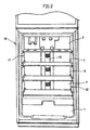
- FIG. 2 is a perspective view showing the inside of the separate cooling refrigerator having the rotary blade.
- the refrigeration compartment 10 is partitioned and the lowermost portion of the partitioned refrigeration compartment 10 is used as a crisper 1.
- the refrigeration compartment 10 exclusive of the crisper 1 is partitioned into four portions, wherein an uppermost portion 2 is generally called a fresh compartment.
- the remaining portions will be called first, second and third portions 5, 6 and 7 from the top down.
- the first, second and third portions 5, 6 and 7 are called 3H/4, 1H/2 and 1H/3 rooms, respectively.
- Two temperature sensors 11 and 22 are placed in the refrigerator compartment 10, wherein an S1 temperature sensor 11 for sensing the temperature of the upper left portion of the refrigeration compartment 10 is attached at the left wall of the first portion 5 (i.e., 3H/4 room) and an S2 temperature sensor 12 for sensing the temperature of the lower right portion of the refrigeration compartment 10 is attached at the right wall of the third portion 7 (i.e., 1H/3 room).
- a cool air discharging portion 15 is at the center of the rear wall of the refrigeration compartment 10.
- the discharge of cool air from the cool air discharging portion 15 is controlled by the rotary blade 20.
- FIG. 3 is an enlarged perspective view of the rotary blade.
- the rotary blade 20 is divided into an upper blade 21, a middle blade 22 and a lower blade 23, which locates corresponding to the first, second and third portions 5, 6 and 7.
- the upper, middle and lower blades 21, 22 and 23 rotate integrally centered around a rotary shaft 25.
- the upper, middle and lower blades 21, 22 and 23 are displaced from each other by 60°, directing air at different directions.
- the cool air discharging direction into the first, second and third portions 5, 6 and 7 are controlled according the stationary angle of the rotary blade 20.
- the rotary blade 20 can ventilate the cool air while being pointed toward a predetermined direction to intensively discharge the cool air into a high-temperature portion, or evenly discharge the cool air into the refrigeration compartment 10 while rotating continuously.
- FIG. 4 is a graph showing the operation cycles of the R fan 30, F fan 29, compressor 26 and rotary blade 20 of the separate cooling refrigerator having the rotary blade.
- F represents the operation cycle of the F fan
- C represents that of the compressor
- R represents that of the R fan
- BLADE MOTOR represents that of the rotary blade driving motor for controlling the stop angle of the rotary blade 20, all of which operate at a high pulse.
- the compressor 26 starts to operate and the operation of the R evaporator 28 and the R fan 30 are also started at the same time.
- the F evaporator 27 and the F fan 29 start to operate and then the operation of the R evaporator 28 and the R fan 30 stop with a predetermined time interval from the operation of the F evaporator 27 and the F fan 29.
- the operation of the compressor 26 stops and the operation of the F evaporator 27 and the F fan 29 stops at the same time.
- the compressor 26 repeats the start and stop of the operation with a predetermined cycle.
- the amount of cool air discharged into the refrigeration compartment and the freezer compartment is controlled by controlling the operation stop time of the R evaporator 28 and the operation start time of the F evaporator 27.
- the operational sequence of the R evaporator 28 and the F evaporator 24 may be changed each other.
- the cool air distribution is evenly maintained within the refrigeration compartment of a separate cooling refrigerator in which intensity of cool air discharged into each compartment is effectively controlled.
- a stationary angle of the rotary blade which is for discharging cool air into the highest-temperature portion of the refrigeration compartment, is inferred (hereinafter, the stationary angle required for discharging cool air toward the highest-temperature portion of the refrigeration compartment is referred to as "temperature equilibrium angle") and the stationary angle of the rotary blade is controlled toward the inferred temperature equilibrium angle, thereby evenly distributing cool air into the refrigeration compartment.
- the inference to the temperature equilibrium angle should be performed on the assumption that only two temperature sensors S1 and S2 are used.
- a fuzzy model is constituted based on the real measured temperature values to calculate the temperature equilibrium angle of the rotary blade.
- the temperature equilibrium angle of the rotary blade is calculated as follows based on the fuzzy mode.
- change in temperatures of total six portions in the left and right of the first, second and third portions 5, 6 and 7 within the refrigeration compartment are measured according to the stationary angle of the rotary blade 20. Also, this temperature measurement is repeatedly performed with respect to a plurality of refrigerators. Then, the obtained data is expressed in a table to be used as a base data to the fuzzy inference.
- the fuzzy inference is performed using the Takagi-Sugeno-Kang (TSK) fuzzy model, and the Genetic algorithm (GA) is also used for more precise inference during the fuzzy inference.
- the temperature equilibrium angle of the rotary blade, for maintaining the temperature equilibrium is inferred by the fuzzy inference as follows.
- the inference target portions within the refrigeration compartment 10 are set as six including t1, t2, t3, t4, t5 and t6, wherein t1 and t2 corresponds to the left and right of the first portion (3H/4 room), t3 and t4 corresponds to the left and right of the second portion (1H/2 room), and t5 and t6 corresponds to the left and right of the third portion (1H/3 room).
- temperature sensors are set at six portions (t1 through t6) to measure change in temperatures therein.
- a reference angle of the rotary blade is set based on a specific blade constituting the rotary blade in consideration of different stationary angles at each room.
- the upper blade 21 is selected as the base blade.
- a reference direction of the rotary blade for measuring the stationary angle may different by selection, however, the stationary angle is set here as 0° when the upper blade 21 of the rotary blade discharges cool air toward the leftmost portion of the refrigeration compartment 10.
- the stationary angle of the rotary blade becomes 180°.
- While the rotary blade 20 is pointed toward the portion having the stationary angle of 0°, temperatures at six portions are measured with a predetermined time interval, and then temperataure descending rate at each portion is calculated to be used as a data for the position having the stationary angle of 0°.
- temperataure descending rate at each portion is calculated to be used as a data for the position having the stationary angle of 0°.
- temperature descending rate at each portion is calculated in the same manner as the above, and then the result is recorded in Table 1.
- the cool air discharging direction of the rotary blade may be different by each blade constituting the rotary blade and the inner structure of the refrigeration compartment 10 are different at each portion, the temperature descending rate is different from each portion.
- a false temperature distribution is obtained using several hundred of data as shown in Table 1, the optimum stationary angle of the rotary blade is calculated from the false temperature distribution.
- the optimum stationary angle of the rotary blade 20 (i.e., "temperature equilibrium angle") for the temperature equilibrium within the refrigeration compartment is inferred using input variables of t1, t2, t3, t4, t5 and t6 and an output variable of "ang", wherein t1 and t2 represent temperatures at the left and right of the 3H/4 room, t3 and t4 represent temperatures at the left and right of the 1H/2 room, and t3 and t4 represent temperatures at the left and right of the 1H/3 room, and "ang" as the output variable represents the temperature equilibrium angle.
- the unbiasedness criterion (UC) is applied to the formula (1), wherein the UC is generally used in the group method of data handling (GMDH) which is for modeling the relationship between input and output variables in a nonlinear system into a polynomial expression.
- GMDH group method of data handling
- the input data is divided into two groups A and B .
- the degree in data scattering is controlled to be nearly the same between the groups.
- the group A should not include many data having small value of t1 and adversely the group B should not include many data having great value of t1.
- the data is substituted for the variables of the following formula (2) to obtain the value of UC.
- n A represents the number of data in group A
- n B represents the number of data in group B
- Y YAA / 1 represents an output estimated from group A by the fuzzy model which is obtained by group A
- Y AB / 1 represents an output estimated from group A by the fuzzy model which is obtained by group B
- Y BB / 1 represents an output estimated from group B by the fuzzy model which is obtained by group B
- Y BA / 1 represents an output estimated from group B by the fuzzy model which is obtained by group A
- the first term represents the difference between the estimated outputs between the groups A and B with respect to the input data of the group A
- the second term represents the difference between the estimated outputs between the groups A and B with respect to the intput data of the group B .
- UC (1) The value of UC obtained from the above is called UC (1) and the calculated UC (1) is 2.16.
- the process for selecting the fuzzy division structure whose UC value becomes minimum is proceeded as follows.
- a fuzzy model accompanying two plant rules is established.
- the selection of variables and fuzzy division are considered simultaneously.
- a structure having one of variables t1, t2, t3, t4, t5, t6 and t7 as a variable of the precondition part is premised and the data area is divided into two.
- the following six structures are considered for the precondition part. That is, the fuzzy state of the variables t1-t6 of the precondition part is divided into a low temperature state ("SMALL") and a high temperature state (“BIG”), and fuzzy functions representing the degree of SMALL and BIG are obtained.
- SMALL low temperature state
- BIG high temperature state
- each UC is obtained from the output variables to the above six structures.
- fuzzy division area parameter of the precondition part
- GA genetic algorithm
- P1 and P2 represent the lower and upper limits in the range corresponding to the SMALL
- P3 and P4 represent the lower and upper limits in the range corresponding to the BIG.
- the structure of the fuzzy function is determined by four parameters P1, P3, P2 and P4.
- the temperature of the refrigeration compartment is controlled in the range from -10°C to 20°C, which is reasonable temperature range within the refrigeration compartment.
- the temperature range is fractionated by 0.1°C to construct strings each having 300 bits. Arbitrary four bits among 300 bits of each string are filled with "1" and the remaining bits are filled with "0" to form a random string. Here, several hundred of random strings are constructed.
- the GA is applied to the process of the fuzzy inferrence using the random strings and the measured values of Table 1.
- correlation coefficients between each random string and the measured values are obtained, and then the upper 10% of random strings having great correlation coefficients, the lower 10% of random strings having small correlation coefficients, and the remaining random strings are classified as upper, lower and middle groups, respectively.
- the upper group is reproduced and the lower group is selected.
- the middle group generates new random strings through the crossover with the upper group.
- correlation coefficients are obtained from the newly generated random strings, and then reproduction, selection and crossover are repeated.
- the correlation coefficients of the repeatedly generated random strings are continuously compared each other until greater coefficient than the currently compared coefficient does not exist. If greater multiple coefficient than the currently compared coefficient does not exist, data of the corresponding random string is determined as the parameters of the precondition part, corresponding to P1, P2, P3 and P4.
- the value of UC is obtained according to the parameters.
- the obtained value of UC is for the (2-1) structure, which is expressed as UC (2-1) .
- UC (2-2) (2.119) ⁇ UC (2-3) (2.157) ⁇ UC (1) (2.16) ⁇ UC (2-1) (2.202) ⁇ UC (2-5) (2.215) ⁇ UC (2-6) (2.223) ⁇ UC (2-4) (2.235)
- UC (x-y) (z) assuming that the value of UC with respect to each structure is expressed as UC (x-y) (z), x represents the number of divided data area, y represents each structure, and z represented calculated value of UC, respectively.
- UC (2-6) (2.223) means that the UC value of the sixth structure of the two-divided data area is equal to 2.223.
- the least value of UC is with respect to the second structure in the two-divided data area. Accordingly, a new three-divided structure is made based on the two-divided structure with respect to the variable t2.
- a data area of t2-ti should be made by adding a new variable.
- the variables t1, t3, t4, t5 and t6 may be taken as the ti, so that many structures may be made.
- the variables having the value of UC which is larger than UC (1) are omitted. Accordingly, t2-t3 data area is fuzzy-divided into three in the current system.
- the obtained structures are shown in FIGS. 6A to 6C.
- FIGS. 6A to 6C are graphs each showing the divided structure when the data shown in Table 1 is fuzzy-divided into three.
- the variables t2 and t3 are designated as the horizontal and vertical axes, respectively. Since the fuzzy division is performed based on the variable t2, the fuzzy division can be performed by three methods.
- the fuzzy function according to the fuzzy division and the output variable "ang" of the function representing the first structure of the three-divided structure (hereinafter, referred to as (3-1) structure), are shown as follows.
- 3-1 structure the fuzzy function according to the fuzzy division and the output variable "ang" of the function, representing the first structure of the three-divided structure
- the fuzzy function according to the fuzzy division and the output variable "ang" of the function, representing the second structure of the three-divided structure (hereinafter, referred as to (3-2) structure), are shown as follows.
- the fuzzy function according to the fuzzy division and the output variable "ang" of the function, representing the third structure of the three-divided structure (hereinafter, referred as to (3-3) structure), are shown as follows.
- the fuzzy division area shown in FIG. 6C that is, the (3-3) structure, has the parameters for the precondition part shown in FIG. 7.
- the above parameters are obtained using the GA as the STAGE 2.
- the temperature of the refrigeration compartment is controlled in the range from -10°C to 20°C, which is reasonable temperature range within the refrigeration compartment.
- the temperature range is fractionated by 0.1°C to construct strings each having 300 bits. Arbitrary eight bits among 300 bits of each string are filled with "1" and the remaining bits are filled with "0" to form a random string. Here, several hundred of random strings are constructed.
- the GA is applied using the random strings and the measured values of Table 1.
- correlation coefficients between each random string and the measured values are obtained, and then the upper 10% of random strings having great correlation coefficients, the lower 10% of random strings having small correlation coefficients, and the remaining random strings are classified as upper, lower and middle groups, respectively.
- the upper group is reproduced and the lower group is selected.
- the middle group generates new random strings through the crossover with the upper group.
- correlation coefficients are obtained from the newly generated random strings, and then reproduction, selection and crossover are repeated.
- the correlation coefficients of the repeatedly generated random strings are continuously compared each other until greater coefficient than the currently compared coefficient does not exist. If greater coefficient than the currently compared coefficient does not exist, data of the corresponding random string is determined as the parameters of the precondition part, corresponding to P1, P2, P3, P4, P5, P6, P7 and P8.
- the value of UC is obtained according to the parameters.
- the obtained UC value is for the (3-3) structure shown in FIG. 6C.
- the UC values with respect to the (3-1) and (3-2) structures are obtained by the same method, and then all UC values are compared to select the structure having the least UC value. Then, the data area of the selected structure is divided into four to obtain four fuzzy rules.
- the fuzzy division into four is performed when UC (3-1) , UC (3-2) , and UC (3-3) are less than UC (2-2) . On the contrary, if those are larger than UC (2-2) , the fuzzy rule having the UC (2-2) , is determined as a final without the fuzzy division into four.
- the comparison in the UC values obtained in the current system is as follows. UC (3-3) (1.92) ⁇ UC (3-1) (1.97) ⁇ UC (3-2) (1.98) ⁇ UC (2-2) (2.119)
- the (3-3) structure has the least UC value.
- a new four-divided structure is constructed based on the (3-3) structure.
- the structure of the precondition part of the fuzzy model in the STAGE 3 is further fractionated to establish a fuzzy model accompanying four plant rules.
- the corresponding structure is considered as a start structure for the fuzzy division into four.
- the (3-3) structure of STAGE 3 having the least UC value is selected as a base structure for the fuzzy division into four.
- FIGS. 8A through 8D are graphs each showing the divided structure when the data shown in Table 1 is fuzzy-divided into four, wherein the variables t2 and t3 are designated as the horizontal and vertical axes, respectively. There are four method for the fuzzy division based on the (3-3) structure.
- the UC values with respect to the above four fuzzy division structures (hereinafter, referred to as (4-1) to (4-4) structures) are obtained by the same method in STAGE 3. Each UC value is compared as follows. UC (4-1) (1.871) ⁇ UC (4-2) (1.904) ⁇ UC (4-3) (1.906) ⁇ UC (4-4) (1.912) ⁇ UC (3-3) (1.92)
- the five-fuzzy division is performed based on the (4-1) structure having the least UC value. However, all UC values of the structures obtained from the five-fuzzy division are larger than UC (4-1) .
- the temperature equilibrium angle of the rotary blade for the optimum temperature equilibrium within the refrigeration compartment has the first structure of the four-fuzzy division (i.e., (4-1) structure) for the precondition part.
- the parameters of the precondition part are shown in FIG. 9, which are obtained by applying the GA as in the STAGES 2 and 3.
- the final temperature equilibrium angle ang(k+1) of the rotary blade is calculated from the above fuzzy model using the following formulas (3) and (4).
- W1 min [1, max ⁇ 0,(1.06-t2)/(-0.96) ⁇ ]
- W2 min [1, max ⁇ 0,(4.86-t3)/1.32) ⁇ ]
- W3 min [1, max ⁇ 0,(4.8-t3)/1.47) ⁇ ]
- W4 min [1, max ⁇ 0,(3.54-t2)/3.35 ⁇ ]
- W5 min [1, max ⁇ 0,(1.06-t2)/(-0.93) ⁇ ]
- W6 min [1, max ⁇ 0, (3.62-t2)/3.35 ⁇ ]
- W1, W2, W3, W4, W5 and W6 represent weights, for reflecting the degree in the contribution of the input variables of each data area in the finally determined (4-1) structure to the fuzzy function, which is obtained according to a general theory of the TSK fuzzy inference.
- ang(k+1) W1W2 ang1 + W1(1-W3)ang2 + W4(1-W5) ang3 +(1-W2) ang4
- the stationary angle of the rotary blade 20 is controlled according to the calculated temperature equilibrium angle ang(k+1) as shown in FIG. 10 in which the cool air is discharged into the left of the refrigeration compartment. That is, the cool air is discharged into the highest-temperature position, thereby evenly maintaining temperature within the refrigeration compartment.
- FIG. 11 is a schematic sectional view showing the state where the cool air is evenly discharged into the refrigeration compartment by the rotation of the rotary blade.
- FIG. 12 is a block diagram illustrating the temperature controlling method according to the present invention.
- the overall control is performed by a microprocessor 31.
- the microprocessor 31 includes a fuzzy inference portion (not shown) in which the fuzzy inference for the temperature equilibrium within the refrigeration compartment is performed based on the temperatures measured by S1 and S2 temperature sensors 11 and 12, and then the obtained temperature data are provided to a rotary blade position controller 35.
- An F temperature sensor 33 is for sensing temperature within the freezer compartment. The amount of cool air to be discharged into the freezer compartment and the refrigeration compartment for the separate cooling is determined by using the F temperature sensor 33, and the S1 and S2 temperature sensors 11 and 12.
- the R fan 30, R evaporator 28, F fan 29 and F evaporator 27 are controlled according to the determined amount of cool air to be discharged into each compartment.
- the result obtained from the calculation by the fuzzy inference position of the microprocessor 31 is provided to the rotary blade position controller 35, and the rotary blade position controller 35 controls the stationary angle of the rotary blade to the temperature equilibrium angle or rotates the rotary blade 20 at a predetermined velocity.
- a rotary blade position sensor 39 senses the real stationary angle of the rotary blade and provides the result to the microprocessor 31, and the microprocessor 31 compares the real stationary angle with the temperature equilibrium angle to correct error therebetween, thereby much precisely controlling the stationary angle of the rotary blade.
- the temperature controlling method for the separate cooling refrigerator having a rotary blade in which the refrigeration compartment and the freezer compartment are separately cooled by installing an evaporator and a ventilation fan in each compartment, respectively, and a refrigerant is provided into the F evaporator and the R evaporator.
- the temperature equilibrium angle of the rotary blade is inferred by the fuzzy inference to discharge cool air into the highest-temperature portion within the refrigerator compartment, and the cool air discharging cycle is controlled by the compressor and the R ventilation fan, thereby evenly maintaining the temperature within the refrigeration compartment.
Landscapes
- Engineering & Computer Science (AREA)
- Chemical & Material Sciences (AREA)
- Combustion & Propulsion (AREA)
- Physics & Mathematics (AREA)
- Mechanical Engineering (AREA)
- Thermal Sciences (AREA)
- General Engineering & Computer Science (AREA)
- Devices That Are Associated With Refrigeration Equipment (AREA)
- Cold Air Circulating Systems And Constructional Details In Refrigerators (AREA)
Claims (11)
- Kühlschrank, der aufweist:einen Gefrierraum;einen Kühlraum, der eine rotierende Klappe (20) an der Rückseite davon besitzt;einen Kompressor (26);einen ersten Verdampfer (27) und einen ersten Ventilationslüfter (29) in dem Gefrierraum zum Kühlen des Gefrierraums;einen zweiten Verdampfer (28) und einen zweiten Ventilationslüfter (30) in dem Kühlraum zum Kühlen des Kühlraums;einen Gefrierraum-Temperatursensor in dem Gefrierraum;zwei Kühlraum-Temperatursensoren (11,12) in dem Kühlraum; undeine Steuereinrichtung (31, 35), die so konfiguriert ist, um die Schritte auszuführen:(a) Steuern des Lüfters (29, 30) so, um geeignet kühlende Luft zu dem Gefrierraum und dem Kühlraum in Abhängigkeit eines Vergleichs der Temperaturen, gemessen durch den Gefrierraum-Temperatursensor und mindestens einen der Kühlraum-Temperatursensoren, zu verteilen;(b) Verwenden eines Fuzzy-Modells, um die Temperatur in einer vorbestimmten Anzahl von Bereichen des Kühlraums von Messungen, vorgenommen durch die Kühlraum-Temperatursensoren (11,12), abzuleiten und eine Temperatur-Gleichgewicht-Winkelposition für die rotierende Klappe, erforderlich zum Abgeben von kühler Luft in den Bereich des Kühlraums, der die höchste, abgeleitete Temperatur besitzt, abzuleiten; und(c) Einstellen der rotierenden Klappe (20) stationär an der Winkelposition.
- Kühlschrank nach Anspruch 1, wobei die Steuereinrichtung (31, 35) so konfiguriert ist, dass Schritt (a) ein Kontrollieren des Verhältnisses der Betriebszeiten des ersten Ventilationslüfters (29) und des ersten Verdampfers (27) einerseits und des zweiten Ventilationslüfters (30) und des zweiten Verdampfers (28) andererseits in Bezug auf den betriebsmäßigen Zyklus des Kompressors (26) aufweist.
- Kühlschrank nach Anspruch 2, wobei die Steuereinrichtung (31, 35) so konfiguriert ist, dass Schritt (a) die Schritte aufweist:wobei die Schritte (a-1) bis (a-4) sequenziell mit der Stop-Zeit des zweiten Verdampfers (28) und der Start-Zeit des ersten Verdampfers (27) wiederholt werden, gesteuert so, um dadurch die Menge an kühlender Luft, die in den Gefrierraum und den Kühlraum abgegeben werden sollen, zu kontrollieren.(a-1) Starten des Kompressors (26), des zweiten Verdampfers (28) und des zweiten Ventilationslüfters (30);(a-2) Starten des ersten Verdampfers (27) und des ersten Ventilationslüfters (29) zu einer vorbestimmten Zeit nach Schritt (a-1);(a-3) Stoppen des zweiten Verdampfers (28) und des zweiten Ventilationslüfters (30) zu einer vorbestimmten Zeit nach Schritt (a-2); und(a-4) Stoppen des ersten Verdampfers (27) und des ersten Ventilationslüfters (29) zu einer vorbestimmten Zeit nach Schritt (a-3),
- Kühlschrank nach einem vorhergehenden Anspruch, wobei die Steuereinrichtung (31, 35) so konfiguriert ist, dass Schritt (b) ein Durchführen einer Fuzzy-Ableitung entsprechend eines vorbestimmten Fuzzy-Modells unter Verwendung der Temperaturen, gemessen durch die Kühlraum-Temperatursensoren (11, 12), um die Temperatur-Gleichgewichtwinkelposition, erforderlich für die rotierende Klappe (20), einzurichten, wobei die Temperatursensoren (11,12) an Wänden des Kühlraums befestigt sind, aufweist.
- Kühlschrank nach einem vorhergehenden Anspruch, wobei die Steuereinrichtung (31, 35) so konfiguriert ist, dass die rotierende Klappe (20) unter einer konstanten Geschwindigkeit gedreht wird, wenn die Temperaturen, abgeleitet in Schritt (b), innerhalb eines vorbestimmten Fehlerbereichs liegen.
- Verfahren zum Herstellen eines Kühlschranks nach einem vorhergehenden Anspruch, wobei das Verfahren aufweist:wobei der Kühlschrank, der so hergestellt ist, ein Kühlschrank gemäß einem vorhergehenden Anspruch ist.(b-1) Erfassen von Temperatur-Änderungsraten-Daten für vorbestimmte Bereiche einer Vielzahl von Testkühlräumen über die Zeit für eine Vielzahl von Winkelpositionen der rotierenden Klappe;(b-2) Erzeugen eines Fuzzy-Modells von den erfassten Daten;(b-3) Programmieren des Fuzzy-Modells in die Steuereinrichtung (31, 35) für den Kühlschrank; und(b-4) Aufbauen eines Kühlschranks so, um die Steuereinrichtung (31, 35) zu umfassen,
- Verfahren nach Anspruch 6, wobei Schritt (b-2) die Schritte aufweist:(b-2-1) Unterteilen der erfassten Daten entsprechend einer Vielzahl von Datenbereichen, um lineare Formeln für jeden Datenbereich zu berechnen;(b-2-2) Berechnen eines unbefangenen Kriterium-Werts in Bezug auf jede Formel; (b-2-3) Vergleichen der unvoreingenommenen Kriterium-Werte, um den geringsten auszuwählen;(b-2-4) Wiederholtes Durchführen der Schritte (b-2-1) bis (b-2-3) in Bezug auf den Datenbereich, der das geringste, unvoreingenommene Kriterium besitzt, um eine datenmäßig unterteilte Struktur zu erhalten, die den geringsten, unvoreingenommenen Kriterium-Wert besitzt, und Ableiten einer linearen Formel entsprechend einem Schlußfolgerungsteil der Fuzzy-Ableitung basierend auf der datenmäßig unterteilten Struktur, die den geringsten, unvoreingenommenen Kriterium-Wert besitzt.
- Verfahren nach Anspruch 7, wobei die Schritte (b-2-2) die Schritte aufweisen:(b-2-2-1) Berechnen von Parameter-Werten, die einen Fuzzy-Bereich der datenmäßig unterteilten Struktur darstellen; und(b-2-2-2) Berechnen des unvoreingenommenen Kriterium-Werts basierend auf den Parameter-Werten.
- Verfahren nach Anspruch 8, wobei der Schritt (b-2-2-1) die Schritte aufweist:(b-2-2-1-1) Bestimmen der Zahl von Parametern des Fuzzy-Bereichs, der die Fuzzy-Strukturen bildet;(b-2-2-1-2) Unterteilen des Wahrscheinlichkeits-Temperaturbereichs des Testkühlraums durch eine vorbestimmte Zahl von Bits, um Folgen zu konstruieren;(b-2-2-1-3) Füllen der Bits jeder Folge, wobei die Zahl von Bits der Zahl der Parameter entspricht, und der verbleibenden Folge der Folgen mit unterschiedlichen binären Zahlen, um eine Vielzahl von Zufalls-Folgen zu bilden;(b-2-2-1-4) Berechnen eines Korrelationskoeffizienten zwischen den Zufalls-Folgen undden gemessenen Temperaturen; und(b-2-2-1-5) Heranziehen von Informationen der Zufalls-Folge, die den größten Korrelationskoeffizienten besitzt, als den Wert-Parameter.
- Verfahren nach Anspruch 9, das die Schritte aufweist:Reproduzieren einer oberen Gruppe entsprechend den oberen 10% von Zufalls-Folgen, die große Korrelationskoeffizienten haben, und Auswählen der unteren Gruppe entsprechend zu den unteren 10% von Zufalls-Folgen, die kleine Korrelationskoeffizienten haben; Überkreuzen der mittleren Gruppe, eine andere als die obere und untere Gruppe, mit der oberen Gruppe; undBerechnen eines Korrelationskoeffizienten von nur einer korrigierten oberen Gruppe, erhalten durch Addieren der Zufalls-Folgen, erhalten durch das Überkreuzen, die die größten Korrelationskoeffizienten haben, zu der oberen Gruppe,Folgen dem Schritt (b-2-2-1-5).
- Verfahren nach Anspruch 7, wobei in dem Schritt (b-2-4) eine lineare Formel, die eine Gewichtung jedes Fuzzy-Bereichs in der datenmäßig unterteilten Struktur zu dem Temperaturgleichgewicht innerhalb der Testkühlräume wiedergibt, berechnet wird.
Applications Claiming Priority (4)
| Application Number | Priority Date | Filing Date | Title |
|---|---|---|---|
| KR9613970 | 1996-04-30 | ||
| KR19960013970 | 1996-04-30 | ||
| KR9711844 | 1997-03-31 | ||
| KR1019970011844A KR100195153B1 (ko) | 1996-04-30 | 1997-03-31 | 회전 날개를 구비한 독립 냉각 냉장고의 온도제어방법 |
Publications (2)
| Publication Number | Publication Date |
|---|---|
| EP0805320A1 EP0805320A1 (de) | 1997-11-05 |
| EP0805320B1 true EP0805320B1 (de) | 2003-01-02 |
Family
ID=26631793
Family Applications (1)
| Application Number | Title | Priority Date | Filing Date |
|---|---|---|---|
| EP97302954A Expired - Lifetime EP0805320B1 (de) | 1996-04-30 | 1997-04-30 | Kühlschrank mit eine rotierende Luftführungsklappe aufweisendem Kühlfach und Verfahren zur dessen Herstellung |
Country Status (6)
| Country | Link |
|---|---|
| US (1) | US5778688A (de) |
| EP (1) | EP0805320B1 (de) |
| JP (1) | JP3142500B2 (de) |
| KR (1) | KR100195153B1 (de) |
| CN (1) | CN1136423C (de) |
| DE (1) | DE69718095T2 (de) |
Cited By (2)
| Publication number | Priority date | Publication date | Assignee | Title |
|---|---|---|---|---|
| EP2881686A1 (de) | 2013-12-05 | 2015-06-10 | V-Zug AG | Kühlgerät, insbesondere Haushaltskühlschrank, mit mehreren Temperaturzonen und Temperatursteuerung |
| CN110579059A (zh) * | 2019-09-12 | 2019-12-17 | 合肥华凌股份有限公司 | 冰箱及其控制方法和装置 |
Families Citing this family (28)
| Publication number | Priority date | Publication date | Assignee | Title |
|---|---|---|---|---|
| TW422331U (en) * | 1997-04-25 | 2001-02-11 | Mitsubishi Electric Corp | Refrigerator |
| KR100234115B1 (ko) * | 1997-07-24 | 2000-07-01 | 윤종용 | 냉기분배장치를 갖는 냉장고 및 냉장고의 제어방법 |
| EP0899524B1 (de) * | 1997-08-29 | 2003-08-20 | Samsung Electronics Co., Ltd. | Kühlschrank mit Kühlluftverteilungsmitteln |
| KR100218940B1 (ko) * | 1997-09-30 | 1999-09-01 | 윤종용 | 냉장고의 제어방법 및 냉장고용 냉기분배장치 |
| US6343477B1 (en) * | 1999-02-26 | 2002-02-05 | Maytag Corporation | Refrigerator food storage temperature control system |
| US6612116B2 (en) | 1999-02-26 | 2003-09-02 | Maytag Corporation | Thermoelectric temperature controlled refrigerator food storage compartment |
| US6463752B2 (en) | 1999-02-26 | 2002-10-15 | Maytag Corporation | Refrigerator food storage compartment with quick chill feature |
| US6505475B1 (en) | 1999-08-20 | 2003-01-14 | Hudson Technologies Inc. | Method and apparatus for measuring and improving efficiency in refrigeration systems |
| KR20010060456A (ko) | 1999-12-27 | 2001-07-07 | 윤종용 | 냉장고의 운전 제어장치 |
| US6405548B1 (en) | 2000-08-11 | 2002-06-18 | General Electric Company | Method and apparatus for adjusting temperature using air flow |
| DE10064318A1 (de) * | 2000-12-22 | 2002-07-04 | Bsh Bosch Siemens Hausgeraete | Verfahren zur Regelung eines Kühlgerätes |
| ITMI20012427A1 (it) | 2001-11-16 | 2003-05-16 | Whirlpool Co | Frigorifero con vano interno suddivisibile in zone a temperature indipendenti |
| KR100446779B1 (ko) * | 2002-07-26 | 2004-09-01 | 엘지전자 주식회사 | 냉장고의 2자유도 냉기공급장치 |
| KR100446780B1 (ko) * | 2002-07-26 | 2004-09-01 | 엘지전자 주식회사 | 냉장고의 냉기토출장치 |
| US6694758B1 (en) * | 2002-08-14 | 2004-02-24 | Lg Electronics Inc. | Apparatus and method for controlling concentrated cooling of refrigerator |
| KR100459458B1 (ko) * | 2002-08-14 | 2004-12-03 | 엘지전자 주식회사 | 냉장고의 냉기토출장치 |
| KR101338012B1 (ko) | 2002-12-09 | 2013-12-09 | 허드슨 테크놀로지스, 인코포레이티드 | 냉각 시스템 최적화 방법 및 장치 |
| US8463441B2 (en) * | 2002-12-09 | 2013-06-11 | Hudson Technologies, Inc. | Method and apparatus for optimizing refrigeration systems |
| US7159409B2 (en) * | 2004-03-01 | 2007-01-09 | Tecumseh Products Company | Method and apparatus for controlling the load placed on a compressor |
| CN100439837C (zh) * | 2004-09-20 | 2008-12-03 | 乐金电子(天津)电器有限公司 | 冰箱的操作控制方法 |
| KR100924733B1 (ko) * | 2005-02-16 | 2009-11-04 | 아세릭 에이. 에스 | 냉각장치 및 그 제어방법 |
| KR100640801B1 (ko) * | 2005-05-10 | 2006-11-02 | 엘지전자 주식회사 | 천장형 에어컨의 베인 제어방법 |
| US9010145B2 (en) * | 2009-06-01 | 2015-04-21 | Samsung Electronics Co., Ltd. | Refrigerator |
| US20130065502A1 (en) * | 2010-03-05 | 2013-03-14 | Electrolux Do Brasil S. A. | System and method of temperature equalization applied to the door of electrical home appliances |
| CN104296490B (zh) * | 2014-10-09 | 2017-01-11 | 合肥美的电冰箱有限公司 | 冰箱的控制方法、系统及冰箱 |
| KR101754359B1 (ko) * | 2015-06-17 | 2017-07-19 | 동부대우전자 주식회사 | 냉장고의 냉기 순환 구조 및 그 제어 방법 |
| CN113932551A (zh) * | 2020-07-13 | 2022-01-14 | 青岛海尔电冰箱有限公司 | 冰箱温度控制方法及冰箱 |
| US11895805B2 (en) | 2022-02-14 | 2024-02-06 | Eagle Technology, Llc | Systems and methods for electronics cooling |
Family Cites Families (15)
| Publication number | Priority date | Publication date | Assignee | Title |
|---|---|---|---|---|
| US4485633A (en) * | 1982-10-18 | 1984-12-04 | The Coca-Cola Company | Temperature-based control for energy management system |
| US4671458A (en) * | 1985-02-25 | 1987-06-09 | Kabushiki Kaisha Toshiba | Air conditioning apparatus |
| KR930004397B1 (ko) * | 1987-02-12 | 1993-05-27 | 미츠비시 덴키 가부시기가이샤 | 냉장고의 온도제어장치 |
| GB2260831B (en) * | 1991-10-18 | 1995-02-15 | Toshiba Kk | Air conditioning apparatus having louver for changing the direction of air into room |
| CN1056225C (zh) * | 1992-03-07 | 2000-09-06 | 三星电子株式会社 | 空调系统 |
| JPH06137738A (ja) * | 1992-10-27 | 1994-05-20 | Matsushita Refrig Co Ltd | 冷凍冷蔵庫の制御装置 |
| JPH06300415A (ja) * | 1993-04-09 | 1994-10-28 | Matsushita Refrig Co Ltd | 冷凍冷蔵庫の制御装置 |
| US5355686A (en) * | 1993-08-11 | 1994-10-18 | Micro Weiss Electronics, Inc. | Dual temperature control of refrigerator-freezer |
| JPH07229668A (ja) * | 1994-02-18 | 1995-08-29 | Matsushita Refrig Co Ltd | 冷凍冷蔵庫の制御装置 |
| MY122559A (en) * | 1994-04-04 | 2006-04-29 | Samsung Electronics Co Ltd | Refrigerator. |
| KR0140460B1 (ko) * | 1994-04-04 | 1998-07-01 | 김광호 | 냉장고의 냉기공급제어장치 및 그 제어방법 |
| KR0170695B1 (ko) * | 1994-11-15 | 1999-03-20 | 윤종용 | 냉장고 및 유전자 알고리즘-퍼지 추론을 적용한 그 온도 제어장치와 방법 |
| US5687580A (en) * | 1994-11-30 | 1997-11-18 | Samsung Electronics Co. Ltd. | Refrigerator and method for controlling temperature thereof by controlling cool air discharge direction |
| KR0155898B1 (ko) * | 1994-11-30 | 1999-01-15 | 김광호 | 냉장고용 냉기토출 제어장치 및 그 제어방법 |
| KR0170697B1 (ko) * | 1994-12-10 | 1999-03-20 | 윤종용 | 냉장고 및 냉기 토출 방향 제어에 의한 그 온도 제어 방법 |
-
1997
- 1997-03-31 KR KR1019970011844A patent/KR100195153B1/ko not_active Expired - Fee Related
- 1997-04-23 US US08/839,075 patent/US5778688A/en not_active Expired - Fee Related
- 1997-04-30 EP EP97302954A patent/EP0805320B1/de not_active Expired - Lifetime
- 1997-04-30 DE DE69718095T patent/DE69718095T2/de not_active Expired - Fee Related
- 1997-04-30 CN CNB971134723A patent/CN1136423C/zh not_active Expired - Fee Related
- 1997-04-30 JP JP09113258A patent/JP3142500B2/ja not_active Expired - Fee Related
Cited By (3)
| Publication number | Priority date | Publication date | Assignee | Title |
|---|---|---|---|---|
| EP2881686A1 (de) | 2013-12-05 | 2015-06-10 | V-Zug AG | Kühlgerät, insbesondere Haushaltskühlschrank, mit mehreren Temperaturzonen und Temperatursteuerung |
| CN110579059A (zh) * | 2019-09-12 | 2019-12-17 | 合肥华凌股份有限公司 | 冰箱及其控制方法和装置 |
| CN110579059B (zh) * | 2019-09-12 | 2021-06-18 | 合肥华凌股份有限公司 | 冰箱及其控制方法和装置 |
Also Published As
| Publication number | Publication date |
|---|---|
| CN1136423C (zh) | 2004-01-28 |
| EP0805320A1 (de) | 1997-11-05 |
| KR970070891A (ko) | 1997-11-07 |
| DE69718095T2 (de) | 2003-04-30 |
| DE69718095D1 (de) | 2003-02-06 |
| JPH1038438A (ja) | 1998-02-13 |
| US5778688A (en) | 1998-07-14 |
| KR100195153B1 (ko) | 1999-06-15 |
| CN1174976A (zh) | 1998-03-04 |
| JP3142500B2 (ja) | 2001-03-07 |
Similar Documents
| Publication | Publication Date | Title |
|---|---|---|
| EP0805320B1 (de) | Kühlschrank mit eine rotierende Luftführungsklappe aufweisendem Kühlfach und Verfahren zur dessen Herstellung | |
| EP0805319B1 (de) | Kühlschrank mit Regelung der Lüftergeschwindigkeit und der Stellung einer rotierenden Luftführungsklappe, sowie Verfahren zur dessen Herstellung | |
| JP2686249B2 (ja) | 冷蔵庫及びその温度制御方法 | |
| US6055820A (en) | Refrigerator, temperature controlling apparatus therefor and method thereof adopting GA-fuzzy inference technique | |
| KR100232441B1 (ko) | 냉동 냉장고 | |
| AU695445B2 (en) | Cooling air supply control apparatus of refrigerator and control method thereof | |
| JP5043938B2 (ja) | 冷気循環装置を有する冷蔵庫及び冷気循環の制御方法 | |
| EP2110626B1 (de) | Kältespeicher und betriebsverfahren dafür | |
| CA2409639A1 (en) | Sealed system multiple speed compressor and fan control | |
| US5743104A (en) | Temperature controlling method for refrigerator and apparatus therefor | |
| US5884491A (en) | Temperature controlling apparatus for refrigerator adopting fuzzy interference and method using the same | |
| JP3504185B2 (ja) | 冷蔵庫 | |
| US12061029B2 (en) | Refrigerator appliance with high freezer capacity | |
| KR0136054Y1 (ko) | 냉장고의 냉기조절장치 | |
| KR100377617B1 (ko) | 냉장고의 냉기순환 시스템 | |
| CN114556035B (zh) | 冰箱及其控制方法 | |
| KR100195090B1 (ko) | 유전자 알고리즘-퍼지 추론을 이용한 냉장고 온도 제어 장치 및 방법 | |
| CN114630999B (zh) | 冰箱及其控制方法 | |
| KR102954050B1 (ko) | 냉장고 및 그의 제어방법 | |
| KR100408239B1 (ko) | 사이드 바이 사이드형 냉장고의 급속냉동장치 및 그제어방법 | |
| KR100283779B1 (ko) | 냉장고의 냉기흐름 제어장치 및 제어방법 | |
| JP2000121228A (ja) | 冷凍庫 | |
| CN118960284A (zh) | 一种储藏结构、冰箱及控制方法 | |
| RU2140048C1 (ru) | Способ управления рефрижераторной системой | |
| KR20200031311A (ko) | 냉장고 및 그의 제어방법 |
Legal Events
| Date | Code | Title | Description |
|---|---|---|---|
| PUAI | Public reference made under article 153(3) epc to a published international application that has entered the european phase |
Free format text: ORIGINAL CODE: 0009012 |
|
| AK | Designated contracting states |
Kind code of ref document: A1 Designated state(s): DE FR GB |
|
| 17P | Request for examination filed |
Effective date: 19980428 |
|
| 17Q | First examination report despatched |
Effective date: 20010125 |
|
| GRAG | Despatch of communication of intention to grant |
Free format text: ORIGINAL CODE: EPIDOS AGRA |
|
| RTI1 | Title (correction) |
Free format text: REFRIGERATOR WITH A REFRIGERATION COMPARTMENT HAVING A ROTARY BLADE AND METHOD OF MANUFACTURING THE SAME |
|
| GRAG | Despatch of communication of intention to grant |
Free format text: ORIGINAL CODE: EPIDOS AGRA |
|
| GRAH | Despatch of communication of intention to grant a patent |
Free format text: ORIGINAL CODE: EPIDOS IGRA |
|
| GRAH | Despatch of communication of intention to grant a patent |
Free format text: ORIGINAL CODE: EPIDOS IGRA |
|
| GRAA | (expected) grant |
Free format text: ORIGINAL CODE: 0009210 |
|
| AK | Designated contracting states |
Kind code of ref document: B1 Designated state(s): DE FR GB |
|
| REG | Reference to a national code |
Ref country code: GB Ref legal event code: FG4D Free format text: 20030102 |
|
| REF | Corresponds to: |
Ref document number: 69718095 Country of ref document: DE Date of ref document: 20030206 Kind code of ref document: P |
|
| ET | Fr: translation filed | ||
| PLBE | No opposition filed within time limit |
Free format text: ORIGINAL CODE: 0009261 |
|
| STAA | Information on the status of an ep patent application or granted ep patent |
Free format text: STATUS: NO OPPOSITION FILED WITHIN TIME LIMIT |
|
| 26N | No opposition filed |
Effective date: 20031003 |
|
| PGFP | Annual fee paid to national office [announced via postgrant information from national office to epo] |
Ref country code: FR Payment date: 20080312 Year of fee payment: 12 Ref country code: DE Payment date: 20080508 Year of fee payment: 12 |
|
| PGFP | Annual fee paid to national office [announced via postgrant information from national office to epo] |
Ref country code: GB Payment date: 20080430 Year of fee payment: 12 |
|
| GBPC | Gb: european patent ceased through non-payment of renewal fee |
Effective date: 20090430 |
|
| REG | Reference to a national code |
Ref country code: FR Ref legal event code: ST Effective date: 20091231 |
|
| PG25 | Lapsed in a contracting state [announced via postgrant information from national office to epo] |
Ref country code: DE Free format text: LAPSE BECAUSE OF NON-PAYMENT OF DUE FEES Effective date: 20091103 |
|
| PG25 | Lapsed in a contracting state [announced via postgrant information from national office to epo] |
Ref country code: GB Free format text: LAPSE BECAUSE OF NON-PAYMENT OF DUE FEES Effective date: 20090430 Ref country code: FR Free format text: LAPSE BECAUSE OF NON-PAYMENT OF DUE FEES Effective date: 20091222 |