EP0805362A2 - Hinderniswarnsystem für tieffliegende Fluggeräte - Google Patents
Hinderniswarnsystem für tieffliegende Fluggeräte Download PDFInfo
- Publication number
- EP0805362A2 EP0805362A2 EP97100308A EP97100308A EP0805362A2 EP 0805362 A2 EP0805362 A2 EP 0805362A2 EP 97100308 A EP97100308 A EP 97100308A EP 97100308 A EP97100308 A EP 97100308A EP 0805362 A2 EP0805362 A2 EP 0805362A2
- Authority
- EP
- European Patent Office
- Prior art keywords
- image
- distance image
- distance
- contours
- obstacle
- Prior art date
- Legal status (The legal status is an assumption and is not a legal conclusion. Google has not performed a legal analysis and makes no representation as to the accuracy of the status listed.)
- Granted
Links
- 238000000034 method Methods 0.000 claims description 5
- 238000001514 detection method Methods 0.000 claims description 3
- 238000011156 evaluation Methods 0.000 description 5
- 239000000243 solution Substances 0.000 description 4
- 238000000605 extraction Methods 0.000 description 3
- 230000004927 fusion Effects 0.000 description 3
- 241000282414 Homo sapiens Species 0.000 description 2
- 238000005562 fading Methods 0.000 description 2
- 230000004297 night vision Effects 0.000 description 2
- 241000282412 Homo Species 0.000 description 1
- 238000013459 approach Methods 0.000 description 1
- 230000006735 deficit Effects 0.000 description 1
- 230000004438 eyesight Effects 0.000 description 1
- 238000003384 imaging method Methods 0.000 description 1
- 230000000873 masking effect Effects 0.000 description 1
- 238000005259 measurement Methods 0.000 description 1
- 238000012545 processing Methods 0.000 description 1
Images

Classifications
-
- G—PHYSICS
- G08—SIGNALLING
- G08G—TRAFFIC CONTROL SYSTEMS
- G08G5/00—Traffic control systems for aircraft
- G08G5/20—Arrangements for acquiring, generating, sharing or displaying traffic information
- G08G5/21—Arrangements for acquiring, generating, sharing or displaying traffic information located onboard the aircraft
-
- G—PHYSICS
- G01—MEASURING; TESTING
- G01S—RADIO DIRECTION-FINDING; RADIO NAVIGATION; DETERMINING DISTANCE OR VELOCITY BY USE OF RADIO WAVES; LOCATING OR PRESENCE-DETECTING BY USE OF THE REFLECTION OR RERADIATION OF RADIO WAVES; ANALOGOUS ARRANGEMENTS USING OTHER WAVES
- G01S17/00—Systems using the reflection or reradiation of electromagnetic waves other than radio waves, e.g. lidar systems
- G01S17/86—Combinations of lidar systems with systems other than lidar, radar or sonar, e.g. with direction finders
-
- G—PHYSICS
- G01—MEASURING; TESTING
- G01S—RADIO DIRECTION-FINDING; RADIO NAVIGATION; DETERMINING DISTANCE OR VELOCITY BY USE OF RADIO WAVES; LOCATING OR PRESENCE-DETECTING BY USE OF THE REFLECTION OR RERADIATION OF RADIO WAVES; ANALOGOUS ARRANGEMENTS USING OTHER WAVES
- G01S17/00—Systems using the reflection or reradiation of electromagnetic waves other than radio waves, e.g. lidar systems
- G01S17/88—Lidar systems specially adapted for specific applications
- G01S17/93—Lidar systems specially adapted for specific applications for anti-collision purposes
- G01S17/933—Lidar systems specially adapted for specific applications for anti-collision purposes of aircraft or spacecraft
-
- G—PHYSICS
- G01—MEASURING; TESTING
- G01S—RADIO DIRECTION-FINDING; RADIO NAVIGATION; DETERMINING DISTANCE OR VELOCITY BY USE OF RADIO WAVES; LOCATING OR PRESENCE-DETECTING BY USE OF THE REFLECTION OR RERADIATION OF RADIO WAVES; ANALOGOUS ARRANGEMENTS USING OTHER WAVES
- G01S7/00—Details of systems according to groups G01S13/00, G01S15/00, G01S17/00
- G01S7/48—Details of systems according to groups G01S13/00, G01S15/00, G01S17/00 of systems according to group G01S17/00
- G01S7/4802—Details of systems according to groups G01S13/00, G01S15/00, G01S17/00 of systems according to group G01S17/00 using analysis of echo signal for target characterisation; Target signature; Target cross-section
-
- G—PHYSICS
- G01—MEASURING; TESTING
- G01S—RADIO DIRECTION-FINDING; RADIO NAVIGATION; DETERMINING DISTANCE OR VELOCITY BY USE OF RADIO WAVES; LOCATING OR PRESENCE-DETECTING BY USE OF THE REFLECTION OR RERADIATION OF RADIO WAVES; ANALOGOUS ARRANGEMENTS USING OTHER WAVES
- G01S7/00—Details of systems according to groups G01S13/00, G01S15/00, G01S17/00
- G01S7/48—Details of systems according to groups G01S13/00, G01S15/00, G01S17/00 of systems according to group G01S17/00
- G01S7/483—Details of pulse systems
- G01S7/486—Receivers
- G01S7/487—Extracting wanted echo signals, e.g. pulse detection
-
- G—PHYSICS
- G01—MEASURING; TESTING
- G01S—RADIO DIRECTION-FINDING; RADIO NAVIGATION; DETERMINING DISTANCE OR VELOCITY BY USE OF RADIO WAVES; LOCATING OR PRESENCE-DETECTING BY USE OF THE REFLECTION OR RERADIATION OF RADIO WAVES; ANALOGOUS ARRANGEMENTS USING OTHER WAVES
- G01S7/00—Details of systems according to groups G01S13/00, G01S15/00, G01S17/00
- G01S7/48—Details of systems according to groups G01S13/00, G01S15/00, G01S17/00 of systems according to group G01S17/00
- G01S7/51—Display arrangements
-
- G—PHYSICS
- G08—SIGNALLING
- G08G—TRAFFIC CONTROL SYSTEMS
- G08G5/00—Traffic control systems for aircraft
- G08G5/70—Arrangements for monitoring traffic-related situations or conditions
- G08G5/74—Arrangements for monitoring traffic-related situations or conditions for monitoring terrain
-
- G—PHYSICS
- G01—MEASURING; TESTING
- G01S—RADIO DIRECTION-FINDING; RADIO NAVIGATION; DETERMINING DISTANCE OR VELOCITY BY USE OF RADIO WAVES; LOCATING OR PRESENCE-DETECTING BY USE OF THE REFLECTION OR RERADIATION OF RADIO WAVES; ANALOGOUS ARRANGEMENTS USING OTHER WAVES
- G01S13/00—Systems using the reflection or reradiation of radio waves, e.g. radar systems; Analogous systems using reflection or reradiation of waves whose nature or wavelength is irrelevant or unspecified
- G01S13/88—Radar or analogous systems specially adapted for specific applications
- G01S13/93—Radar or analogous systems specially adapted for specific applications for anti-collision purposes
- G01S13/933—Radar or analogous systems specially adapted for specific applications for anti-collision purposes of aircraft or spacecraft
Definitions
- Natural vision, low light intensifiers or night vision devices are often not sufficient to reliably detect obstacles that can be dangerous to the pilot of a low-flying aircraft or vehicle.
- High-resolution, imaging distance image sensors based on laser radar also provide obstacle information. The problem is the evaluation and ergonomically optimal presentation of this additional information as part of an overall system for obstacle warning for the manually flying pilot.
- a particularly important class of obstacles are cables.
- the object of the invention is to support the pilot in the safe detection of obstacles.
- the obstacle warning system consists of a base sensor (possibly with residual light amplifier, night vision device), a distance image sensor, an evaluation computer for distance image processing, a display with a fade-in function for a second image for the base image (e.g. head-up display, helmet-mounted display) and optionally one Navigation system.
- Fig. 1 shows these system components including their inputs and outputs.
- the obstacle information additionally generated by the distance image sensor is superimposed on it.
- this additional information is not alphanumeric, symbolic or otherwise abstracted, but consists of the real, one-dimensional edge contours of the detected obstacles with which the obstacle contours, which may be less well represented in the basic image, are traced.
- the obstacle warning system completes the basic image, according to which the pilot is flying or driving, through the edge contours of the obstacles in the distance image.
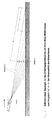
- the additional sensor is a distance image sensor. Because only the distance image allows the robust extraction of contours of any obstacles in real time. To do this, it is sufficient to look for "jumps" between neighboring image pixels in the distance image. A continuously running terrain, for example, has no such jumps. Any obstacle in the terrain, on the other hand, leads to a jump in the distance measurement value at its edge (FIG. 2). Obstacle contours can therefore be extracted in the distance image using high-pass images.
- the correct position of the obstacle contour in the basic image can be calculated at any time from its position in the distance image, taking into account the course of movement of the vehicle or aircraft in all six degrees of freedom. All that is required is to implement appropriate software in the evaluation computer.
- the distance image sensor generally generates its image by means of a vertical or horizontal scan, ie the image is built up in rows or columns over time. For this reason, only those obstacle contours that appear in the currently generated distance image line are shown in the base image, for example in the case of a vertical scan. Their position in the base image is known because of the very short dead time between the detection in the distance image and the overlay in the base image.
- the displayed object contours do not go away immediately, they gradually become weaker. For the pilot as a whole, this depiction looks like a stripe that moves vertically through his image, allowing the contours of obstacles to emerge (similar to a radar screen). This strip has the same frequency as the image build-up on the sensor. The closer this frequency approaches the value of 25 Hz, the better the ergonomics of the contour display.
Landscapes
- Engineering & Computer Science (AREA)
- Physics & Mathematics (AREA)
- General Physics & Mathematics (AREA)
- Radar, Positioning & Navigation (AREA)
- Remote Sensing (AREA)
- Computer Networks & Wireless Communication (AREA)
- Aviation & Aerospace Engineering (AREA)
- Electromagnetism (AREA)
- Traffic Control Systems (AREA)
- Image Analysis (AREA)
Abstract
Description
- Zur sicheren Erfassung von Hindernissen, die dem Piloten eines tieffliegenden Fluggeräts oder eines Fahrzeugs gefährlich werden können, reichen die natürliche Sicht, Restlichtverstärker oder Nachtsichtgeräte häufig nicht aus. Hochauflösende, bildgebende Entfernungsbildsensoren auf Laserradarbasis liefern zusätzlich Hindernisinformation. Das Problem besteht in der Auswertung und ergonomisch optimalen Darstellung dieser Zusatzinformation im Rahmen eines Gesamtsytems zur Hinderniswarnung für den manuell fliegenden Piloten. Eine besonders wichtige Klasse von Hindernissen sind hierbei Leitungen.
- Aufgabe der Erfindung ist die Unterstützung des Piloten bei der sicheren Erfassung von Hindernissen.
- Diese Aufgabe wird durch den Gegenstand des Hauptanspruchs und der Unteransprüche gelöst.
Durch den Gegenstand der Erfindung ergeben sich folgende Vorteile: - Optimale Ergonomie durch eine graphische (nicht symbolische) Darstellung der Hindernisse; ein Mensch kann anhand von Objektkonturen sehr viel besser klassifizieren als jeder Algorithmus.
- Hinderniskonturen sind das graphisch "sparsamste" Mittel der Hindernisdarstellung ohne wesentlichen Informationsverlust; dies führt zu geringen Datenraten am Ausgang des Auswerterechners und zu einer minimalen Verdeckung des Basisbildes durch die zusätzliche Hindernisinformation.
- Das Verfahren zur Konturenextraktion nutzt den Informationsgehalt des Entfernungsbildes optimal aus; dies führt zu einfachen Algorithmen, die auch bei komplexen Hindernisszenen robust arbeiten, und zu geringer Rechenleistung, die beim Auswerterechner erforderlich ist.
- Für Entfernungsbildsensoren, deren Bildrate unter 25 Hz liegt, wurde eine Methode zur Synchronisation mit dem Basisbild entwickelt, die ohne Navigationsdaten auskommt.
- Die Erfindung wird anhand von Fig. näher beschrieben. Es zeigen:
- Fig. 1
- die Systemkomponenten einschließlich des Inputs und Outputs,
- Fig. 2
- die Eigenschaft eines Entfernungsbildes, die Konturen von Hindernissen mit erhöhtem Kontrast abzubilden.
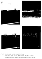
- Fig. 3
- ein Basisbild, ein falschfarbenkodiertes Entfernungsbild, die Anwendung eines Hochpaßfilters auf ein Entfernungsbild und ein Basisbild mit nachgezeichneten Randkonturen von Hindernissen.
- Das erfindungsgemäße Hinderniswarnsystem besteht aus einem Basissensor (gegebenenfalls mit Restlichtverstärker, Nachtsichtgerät), einem Entfernungsbildsensor, einem Auswerterechner zur Entfernungsbildverarbeitung, einem Display mit Einblendfunktion für ein zweites Bild zum Basisbild (z.B. Head-Up-Display, Helmet-Mounted-Display) sowie optional einem Navigationssystem. Fig. 1 stellt diese Systemkomponenten einschließlich ihres In- und Outputs dar.
- Da der Pilot nach dem Basisbild fliegt, wird die vom Entfernungsbildsensor zusätzlich generierte Hindernisinformation in dieses eingeblendet. Diese Zusatzinformation ist aus ergonomischen Gründen nicht alphanumerisch, symbolisch oder anderweitig abstrahiert, sondern besteht aus den realen, eindimensionalen Randkonturen der erfaßten Hindernisse mit denen die im bloßen Basisbild eventuell weniger gut abgebildeten Hinderniskonturen nachgezeichnet werden. Insgesamt vervollständigt das Hinderniswarnsystem das Basisbild, nach dem der Pilot fliegt oder fährt, durch die Randkonturen der Hindernisse im Entfernungsbild.
- Dazu ist es erforderlich, daß der zusätzliche Sensor ein Entfernungsbildsensor ist. Denn nur das Entfernungsbild erlaubt die robuste Extraktion von Konturen beliebiger Hindernisse in Echtzeit. Dazu reicht es aus, im Entfernungsbild nach "Sprüngen" zwischen benachbarten Bildpixeln zu suchen. Ein stetig verlaufendes Gelände z.B. weist keine derartigen Sprünge auf. Jedes Hindernis im Gelände dagegen führt zu einem Sprung des Entfernungsmeßwertes an seinem Rand (Fig. 2). Hinderniskonturen sind daher im Entfernungsbild durch Hochpaßbilder extrahierbar.
- Bei Entfernungsbildsensoren, die eine geringere Bildfrequenz als 25-30 Hz besitzen, ergibt sich bei der Einblendung in das Basisbild das Problem, daß wegen der raschen Änderung des Basisbildes die Lage einer einzublendenden Objektkontur nicht einfach aus dem Sensorbild übernommen werden kann. Es werden zwei Lösungen dieses Problems vorgeschlagen:
- Bei Vorhandensein eines Navigationssystems kann die korrekte Lage der Hinderniskontur im Basisbild zu jedem Zeitpunkt aus dessen Lage im Entfernungsbild berechnet werden, unter Berücksichtigung des Bewegungsverlaufs des Fahrzeugs oder Fluggeräts in allen sechs Freiheitsgraden. Dazu ist lediglich eine entsprechende Software im Auswerterechner zu implementieren.
- Eine kostengünstigere Lösung ist ohne Navigationssystem möglich. Der Entfernungsbildsensor generiert sein Bild in der Regel durch vertikalen oder horizontalen Scan, d.h. das Bild wird im Zeitverlauf zeilen- oder spaltenweise aufgebaut. Deshalb werden - z.B. bei vertikalem Scan - nur diejenigen Hinderniskonturen in das Basisbild eingeblendet, die in der aktuell generierten Entfernungsbildzeile auftreten. Deren Lage im Basisbild ist wegen der sehr geringen Totzeit zwischen der Erfassung im Entfernungsbild und der Einblendung im Basisbild bekannt. Beim weiteren Entfernungsbildaufbau verlöschen die eingeblendeten Objektkonturen nicht sofort sondern sie werden allmählich schwächer. Diese Darstellung wirkt auf den Piloten insgesamt wie ein vertikal durch sein Bild wandernder Streifen, der die Konturen von Hindernissen hervortreten läßt (ähnlich Radarschirm). Dieser Streifen besitzt dieselbe Frequenz wie der Bildaufbau beim Sensor. Je mehr sich diese Frequenz dem Wert 25 Hz nähert, desto besser wird die Ergonomie der Konturdarstellung.
- Die Vorteile und Merkmale des erfindungsgemäßen Hinderniswarnsystems für Fahrzeuge oder tieffliegende Fluggeräte werden nachfolgend zusammengefaßt:
- Verwendung geeigneter Software (digitale Hochpaßfilter) in Verbindung mit einer Entfernungsbildkamera zur datenmäßigen Erfassung der Umrisse ("Konturen") aller Hindernisse;
- Robustheit, Echtzeitfähigkeit und geringe Komplexität der Software wegen des Informationsgehaltes des Entfernungsbildes
- Extraktion graphischer statt symbolischer Information aus dem Entfernungsbild
- hohe Datenredution durch Beschränkung auf die Konturen der Hindernisse.
- Echtzeitbildfusion der gewonnenen graphischen Konturinformation mit dem Basisbild; nach dem der Pilot fährt/fliegt, als graphische Mensch-Maschine-Schnittstelle zwischen Pilot und Hinderniswarnsystem;
- optimale Ergonomie der Hinderniswarnung durch Einblendung realistischer, graphischer Hindernisinformation statt symbolischer Information
- minimale Beeinträchtigung des Basisbildes durch Einblendung bloßer Umrisse von Hindernissen
- Szeneninterpretation durch den Menschen, nicht durch die Maschine.
- Echtzeitbildfusion innerhalb eines wandernden Streifens bei Entfernungsbildkameras mit Bildraten kleiner 25 Hz;
- auf ein präzises Fahrzeugnavigationssystem für die fehlerfreie Bildfusion kann für eine kostengünstigere Lösung verzichtet werden.
Claims (4)
- Hinderniswarnsystem für tieffliegende Fluggeräte mit natürlicher Sicht aus einem Cockpitfenster oder mit einer Kamera, die auf einem Display ein Bild der vor dem Fluggerät liegenden Landschaft (Basisbild) liefert dadurch gekennzeichnet, daß ein Entfernungsbildsensor vorhanden ist, der mittels digitaler Hochpaßfilter einem Head-Up-Display oder dem Display des Basisbilds eindimensional Randkonturen der erfaßten Hindernisse im Landschaftsbild nachzeichnet und dadurch sichtbar macht.
- Verfahren zur Sichtbarmachung der Randkonturen von Hindernissen im Display eines Piloten, dadurch gekennzeichnet, daß digitale Hochpaßfilter auf das Entfernungsbild angewendet werden.
- Verfahren nach Anspruch 2 mit Entfernungsbildsensoren, die eine geringere Bildfrequenz als 25 bis 30 Hz besitzen, dadurch gekennzeichnet, daß der Entfernungsbildsensor sein Bild zum Beispiel durch vertikalen Scan generiert und das Bild im Zeitverlauf zeilenweise aufgebaut wird, wobei nur diejenigen Hinderniskonturen in das Basisbild eingeblendet werden, die in der aktuell generierten Entfernungsbildzeile auftreten und deren Lage wegen der geringen Totzeit zwischen der Erfassung im Entfernungsbild und der Einblendung im Basisbild bekannt ist und daß beim weiteren Entfernungsbildaufbau die bereits eingeblendeten Objektkonturen allmählich schwächer werden.
- Verfahren nach Anspruch 2 mit Entfernungsbildsensoren, die eine geringere Bildfrequenz als 25-30 Hz besitzen und bei Vorhandensein eines Navigationssystems dadurch gekennzeichnet, daß die korrekte Lage der Hinderniskontur im Basisbild zu jedem Zeitpunkt aus dessen Lage im Entfernungsbild berechnet wird, unter Berücksichtigung des Bewegungsverlaufs des Fluggeräts in allen sechs Freiheitsgraden.
Applications Claiming Priority (2)
| Application Number | Priority Date | Filing Date | Title |
|---|---|---|---|
| DE19605218A DE19605218C1 (de) | 1996-02-13 | 1996-02-13 | Hinderniswarnsystem für tieffliegende Fluggeräte |
| DE19605218 | 1996-02-13 |
Publications (3)
| Publication Number | Publication Date |
|---|---|
| EP0805362A2 true EP0805362A2 (de) | 1997-11-05 |
| EP0805362A3 EP0805362A3 (de) | 1999-04-14 |
| EP0805362B1 EP0805362B1 (de) | 2003-03-26 |
Family
ID=7785254
Family Applications (1)
| Application Number | Title | Priority Date | Filing Date |
|---|---|---|---|
| EP97100308A Expired - Lifetime EP0805362B1 (de) | 1996-02-13 | 1997-01-10 | Verfahren zur Hinderniswarnung für tieffliegende Fluggeräte |
Country Status (4)
| Country | Link |
|---|---|
| US (1) | US6243482B1 (de) |
| EP (1) | EP0805362B1 (de) |
| AT (1) | ATE235697T1 (de) |
| DE (1) | DE19605218C1 (de) |
Cited By (1)
| Publication number | Priority date | Publication date | Assignee | Title |
|---|---|---|---|---|
| FR2780380A1 (fr) * | 1998-06-25 | 1999-12-31 | Eurocopter Deutschland | Procede et dispositif pour l'assistance au pilotage d'un avion |
Families Citing this family (27)
| Publication number | Priority date | Publication date | Assignee | Title |
|---|---|---|---|---|
| JP3052286B2 (ja) * | 1997-08-28 | 2000-06-12 | 防衛庁技術研究本部長 | 飛行システムおよび航空機用擬似視界形成装置 |
| DE19831452C1 (de) * | 1998-07-14 | 2000-03-09 | Eurocopter Deutschland | Verfahren zur Unterstützung der Flugführung |
| US6484071B1 (en) * | 1999-02-01 | 2002-11-19 | Honeywell International, Inc. | Ground proximity warning system, method and computer program product for controllably altering the base width of an alert envelope |
| DE10055572C1 (de) * | 2000-11-09 | 2002-01-24 | Astrium Gmbh | Verfahren zur Leitungserkennung für tieffliegende Fluggeräte |
| RU2192368C1 (ru) * | 2001-07-13 | 2002-11-10 | Акционерное общество открытого типа "ОКБ Сухого" | Система контроля взлета или посадки самолета |
| JP3849505B2 (ja) * | 2001-11-26 | 2006-11-22 | 株式会社デンソー | 障害物監視装置及びプログラム |
| US6809704B2 (en) * | 2002-02-08 | 2004-10-26 | Charles J. Kulas | Reduction of blind spots by using display screens |
| US7684624B2 (en) * | 2003-03-03 | 2010-03-23 | Smart Technologies Ulc | System and method for capturing images of a target area on which information is recorded |
| DE102004014041B4 (de) * | 2004-03-19 | 2006-04-06 | Martin Spies | Sensor zur Hinderniserkennung |
| FR2886439B1 (fr) * | 2005-05-24 | 2010-11-05 | Eurocopter France | Procede et dispositif d'aide au pilotage d'un aeronef a basse altitude |
| DE102005047273B4 (de) | 2005-10-01 | 2008-01-03 | Eads Deutschland Gmbh | Verfahren zur Unterstützung von Tiefflügen |
| FR2902537B1 (fr) * | 2006-06-20 | 2016-04-29 | Eurocopter France | Systeme de detection d'obstacles au voisinage d'un point de poser |
| FR2910680B1 (fr) | 2006-12-21 | 2009-01-30 | Eurocopter France | Procede et systeme de traitement et de visualisation d'images de l'environnement d'un aeronef |
| DE102007032084A1 (de) * | 2007-07-09 | 2009-01-22 | Eads Deutschland Gmbh | Kollisions- und Konfliktvermeidungssystem für autonome unbemannte Flugzeuge (UAV) |
| JP4400659B2 (ja) * | 2007-09-03 | 2010-01-20 | トヨタ自動車株式会社 | 車載表示装置 |
| DE102009000136A1 (de) | 2009-01-12 | 2010-07-15 | Robert Bosch Gmbh | Vorrichtung zur Informationsgewinnung aus einem Fahrzeuginnenraum |
| DE102009020636B4 (de) | 2009-05-09 | 2017-09-28 | Hensoldt Sensors Gmbh | Verfahren zur verbesserten Erkennung von leitungsartigen Objekten |
| US8773299B1 (en) * | 2009-09-29 | 2014-07-08 | Rockwell Collins, Inc. | System and method for actively determining obstacles |
| FR2951296B1 (fr) | 2009-10-09 | 2011-11-18 | Thales Sa | Procede de calcul d'alerte pour un systeme avertisseur de proximite du sol d'un aeronef |
| FR2957447B1 (fr) * | 2010-03-15 | 2012-10-26 | Eurocopter France | Procede et dispositif pour voler a l'aide d'un aeronef a basse altitude de maniere securisee |
| US9691281B2 (en) * | 2010-03-24 | 2017-06-27 | Telenav, Inc. | Navigation system with image assisted navigation mechanism and method of operation thereof |
| CA2814183C (en) * | 2010-10-12 | 2018-07-10 | New York University | Apparatus for sensing utilizing tiles, sensor having a set of plates, object identification for multi-touch surfaces, and method |
| DE102013018762A1 (de) * | 2013-04-23 | 2014-10-23 | Frank Spirgatis | Verfahren und Vorrichtung zur Hinderniserkennung |
| US10243647B2 (en) * | 2017-05-30 | 2019-03-26 | Bell Helicopter Textron Inc. | Aircraft visual sensor system |
| US11380054B2 (en) | 2018-03-30 | 2022-07-05 | Cae Inc. | Dynamically affecting tailored visual rendering of a visual element |
| US10964106B2 (en) | 2018-03-30 | 2021-03-30 | Cae Inc. | Dynamically modifying visual rendering of a visual element comprising pre-defined characteristics |
| CN115440094B (zh) * | 2022-07-21 | 2023-11-07 | 南京航空航天大学 | 用于直升机近地告警的障碍物探测方法、装置和存储介质 |
Family Cites Families (28)
| Publication number | Priority date | Publication date | Assignee | Title |
|---|---|---|---|---|
| US3076961A (en) * | 1959-10-27 | 1963-02-05 | Bulova Res And Dev Lab Inc | Multiple-sensor coordinated apparatus |
| US3739380A (en) * | 1960-04-04 | 1973-06-12 | North American Aviation Inc | Slant range tracking terrain avoidance system |
| US4209852A (en) * | 1974-11-11 | 1980-06-24 | Hyatt Gilbert P | Signal processing and memory arrangement |
| US3735398A (en) * | 1971-05-20 | 1973-05-22 | Sperry Rand Corp | Base band short range pre-collision sensor for actuation of vehicle safety apparatus |
| DE2643526C2 (de) * | 1976-09-28 | 1978-07-20 | Licentia Patent-Verwaltungs-Gmbh, 6000 Frankfurt | Optisch-elektronisches Hinderniswarngerät für Piloten von tieffliegenden Fluggeräten, insbesondere Hubschraubern |
| US4232903A (en) * | 1978-12-28 | 1980-11-11 | Lockheed Missiles & Space Co., Inc. | Ocean mining system and process |
| US4674869A (en) * | 1979-04-30 | 1987-06-23 | Diffracto, Ltd. | Method and apparatus for electro-optically determining dimension, location and altitude of objects |
| DE3104300A1 (de) * | 1981-02-07 | 1982-08-19 | Licentia Patent-Verwaltungs-Gmbh, 6000 Frankfurt | "verfahren zur erkennung von ein fahrzeug behindernden hindernissen" |
| DE3110691C2 (de) * | 1981-03-19 | 1985-07-18 | Messerschmitt-Bölkow-Blohm GmbH, 8012 Ottobrunn | Navigationssystem für lenkbare Flugkörper |
| US4988189A (en) * | 1981-10-08 | 1991-01-29 | Westinghouse Electric Corp. | Passive ranging system especially for use with an electro-optical imaging system |
| US4653109A (en) * | 1984-07-30 | 1987-03-24 | Lemelson Jerome H | Image analysis system and method |
| US4796997A (en) * | 1986-05-27 | 1989-01-10 | Synthetic Vision Systems, Inc. | Method and system for high-speed, 3-D imaging of an object at a vision station |
| US4802096A (en) * | 1987-05-14 | 1989-01-31 | Bell & Howell Company | Controlled direction non-contact detection system for automatic guided vehicles |
| US4792904A (en) * | 1987-06-17 | 1988-12-20 | Ltv Aerospace And Defense Company | Computerized flight inspection system |
| US5579444A (en) * | 1987-08-28 | 1996-11-26 | Axiom Bildverarbeitungssysteme Gmbh | Adaptive vision-based controller |
| US4902126A (en) * | 1988-02-09 | 1990-02-20 | Fibertek, Inc. | Wire obstacle avoidance system for helicopters |
| JPH07104943B2 (ja) * | 1988-02-29 | 1995-11-13 | 株式会社日立製作所 | 物体認識装置 |
| US5005147A (en) * | 1988-12-30 | 1991-04-02 | The United States Of America As Represented By The Administrator, The National Aeronautics And Space Administration | Method and apparatus for sensor fusion |
| US5144373A (en) * | 1989-08-02 | 1992-09-01 | Loral Aerospace Corp. | Detection of range discontinuities in stereoscopic imagery |
| DE3939731A1 (de) * | 1989-12-01 | 1991-06-06 | Dornier Luftfahrt | Autonomes landesystem |
| EP0448956B1 (de) * | 1990-03-30 | 2000-09-06 | Lockheed Martin Corporation | Zielerkennung mit Anwendung von Quantisations-Indexen |
| US5170352A (en) * | 1990-05-07 | 1992-12-08 | Fmc Corporation | Multi-purpose autonomous vehicle with path plotting |
| US5477459A (en) * | 1992-03-06 | 1995-12-19 | Clegg; Philip M. | Real time three-dimensional machine locating system |
| IL104542A (en) * | 1993-01-28 | 1996-05-14 | Israel State | Airborne obstacle collision avoidance apparatus |
| JP3679426B2 (ja) * | 1993-03-15 | 2005-08-03 | マサチューセッツ・インスティチュート・オブ・テクノロジー | 画像データを符号化して夫々がコヒーレントな動きの領域を表わす複数の層とそれら層に付随する動きパラメータとにするシステム |
| US5581930A (en) * | 1993-07-13 | 1996-12-10 | Langer; Alexander G. | Remote activity sensing system |
| US5488675A (en) * | 1994-03-31 | 1996-01-30 | David Sarnoff Research Center, Inc. | Stabilizing estimate of location of target region inferred from tracked multiple landmark regions of a video image |
| US5581250A (en) * | 1995-02-24 | 1996-12-03 | Khvilivitzky; Alexander | Visual collision avoidance system for unmanned aerial vehicles |
-
1996
- 1996-02-13 DE DE19605218A patent/DE19605218C1/de not_active Expired - Fee Related
-
1997
- 1997-01-10 EP EP97100308A patent/EP0805362B1/de not_active Expired - Lifetime
- 1997-01-10 AT AT97100308T patent/ATE235697T1/de active
- 1997-02-13 US US08/799,860 patent/US6243482B1/en not_active Expired - Lifetime
Cited By (3)
| Publication number | Priority date | Publication date | Assignee | Title |
|---|---|---|---|---|
| FR2780380A1 (fr) * | 1998-06-25 | 1999-12-31 | Eurocopter Deutschland | Procede et dispositif pour l'assistance au pilotage d'un avion |
| GB2341506A (en) * | 1998-06-25 | 2000-03-15 | Eurocopter Deutschland | Near obstacle warning display |
| GB2341506B (en) * | 1998-06-25 | 2003-02-12 | Eurocopter Deutschland | Wire highlighting system |
Also Published As
| Publication number | Publication date |
|---|---|
| ATE235697T1 (de) | 2003-04-15 |
| EP0805362B1 (de) | 2003-03-26 |
| US6243482B1 (en) | 2001-06-05 |
| EP0805362A3 (de) | 1999-04-14 |
| DE19605218C1 (de) | 1997-04-17 |
Similar Documents
| Publication | Publication Date | Title |
|---|---|---|
| DE19605218C1 (de) | Hinderniswarnsystem für tieffliegende Fluggeräte | |
| DE69413642T2 (de) | Verfahren und Einrichtung zur Steuerungshilfe eines Flugzeuges | |
| DE60020420T2 (de) | Situationsdarstellungs-Anzeigesystem | |
| DE68919811T2 (de) | Flugzeuginstrumentensysteme. | |
| DE69120789T2 (de) | Anzeigevorrichtung für ein Verkehrswarn- und Kollisionsschutzsystem | |
| EP3394708B1 (de) | Verfahren zum betreiben eines virtual-reality-systems und virtual-reality-system | |
| EP3298474B1 (de) | Verfahren zum betreiben einer datenbrille in einem kraftfahrzeug und system mit einer datenbrille | |
| EP1875442B1 (de) | Verfahren zur grafischen darstellung der umgebung eines kraftfahrzeugs | |
| DE19826283B4 (de) | Verfahren zur Anzeige eines vor einem Kraftfahrzeug befindlichen Objektes, insbesondere eines vorausfahrenden Kraftfahrzeuges | |
| DE10030813A1 (de) | Aufmerksamkeitssteuerung für Bediener einer technischen Einrichtung | |
| DE112019007195T5 (de) | Anzeigesteuerungseinrichtung, anzeigesteuerungsverfahren und anzeigesteuerungsprogramm | |
| DE10131720A1 (de) | Head-Up Display System und Verfahren | |
| DE102019105630B4 (de) | Anzeigesteuervorrichtung, Fahrzeugumgebungsanzeigesystem und Computerprogramm | |
| DE102004016331B4 (de) | Vorrichtung und Verfahren zur gleichzeitigen Darstellung virtueller und realer Umgebungsinformationen | |
| DE102017220268B4 (de) | Erkennung und Visualisierung von Systemunsicherheit bei der Darstellung augmentierter Bildinhalte in Head-Up-Displays | |
| WO2019072455A1 (de) | Verfahren zum darstellen einer umgebung eines fahrzeugs | |
| DE102016014712B4 (de) | Fahrzeug und Verfahren zur Ausgabe von Informationen an eine Fahrzeugumgebung | |
| EP1580588A1 (de) | Vorrichtung zur visuellen Darstellung einer Information | |
| WO2019134845A1 (de) | Spiegelersatzsystem sowie verfahren zur darstellung von bild- und/oder videodaten der umgebung eines kraftfahrzeugs | |
| DE102017209802A1 (de) | Verfahren und Vorrichtung zum Betreiben eines Anzeigesystems mit einer Datenbrille | |
| DE102009003220B4 (de) | Verfahren zur Kollisionswarnung sowie Kollisionswarneinrichtung | |
| DE102017114450B4 (de) | Vorrichtung und Verfahren zum Abbilden von Bereichen | |
| EP3833576B1 (de) | Kameraüberwachungssystem | |
| DE102022105187B4 (de) | Verfahren zum Darstellen einer Umgebung eines Fahrzeugs und Anzeigesystem | |
| EP1586861A1 (de) | Verfahren und Vorrichtung zur Darstellung von Fahrerinformationen |
Legal Events
| Date | Code | Title | Description |
|---|---|---|---|
| PUAI | Public reference made under article 153(3) epc to a published international application that has entered the european phase |
Free format text: ORIGINAL CODE: 0009012 |
|
| AK | Designated contracting states |
Kind code of ref document: A2 Designated state(s): AT CH FR GB IT LI |
|
| PUAL | Search report despatched |
Free format text: ORIGINAL CODE: 0009013 |
|
| AK | Designated contracting states |
Kind code of ref document: A3 Designated state(s): AT CH FR GB IT LI |
|
| 17P | Request for examination filed |
Effective date: 19990506 |
|
| 17Q | First examination report despatched |
Effective date: 20010530 |
|
| RTI1 | Title (correction) |
Free format text: METHOD FOR LOW-FLYING AIRCRAFT FOR WARNING OF OBSTACLE |
|
| GRAH | Despatch of communication of intention to grant a patent |
Free format text: ORIGINAL CODE: EPIDOS IGRA |
|
| GRAH | Despatch of communication of intention to grant a patent |
Free format text: ORIGINAL CODE: EPIDOS IGRA |
|
| RTI1 | Title (correction) |
Free format text: METHOD FOR LOW-FLYING AIRCRAFT FOR WARNING OF OBSTACLE |
|
| GRAA | (expected) grant |
Free format text: ORIGINAL CODE: 0009210 |
|
| AK | Designated contracting states |
Designated state(s): AT CH FR GB IT LI |
|
| REG | Reference to a national code |
Ref country code: GB Ref legal event code: FG4D Free format text: NOT ENGLISH |
|
| REG | Reference to a national code |
Ref country code: CH Ref legal event code: EP |
|
| GBT | Gb: translation of ep patent filed (gb section 77(6)(a)/1977) | ||
| ET | Fr: translation filed | ||
| PLBE | No opposition filed within time limit |
Free format text: ORIGINAL CODE: 0009261 |
|
| STAA | Information on the status of an ep patent application or granted ep patent |
Free format text: STATUS: NO OPPOSITION FILED WITHIN TIME LIMIT |
|
| 26N | No opposition filed |
Effective date: 20031230 |
|
| REG | Reference to a national code |
Ref country code: GB Ref legal event code: 732E |
|
| REG | Reference to a national code |
Ref country code: CH Ref legal event code: PUE Owner name: EADS DEUTSCHLAND GMBH Free format text: DORNIER GMBH##88039 FRIEDRICHSHAFEN (DE) -TRANSFER TO- EADS DEUTSCHLAND GMBH#WILLY-MESSERSCHMITT-STRASSE#85521 OTTOBRUNN (DE) Ref country code: CH Ref legal event code: NV Representative=s name: R. A. EGLI & CO. PATENTANWAELTE |
|
| REG | Reference to a national code |
Ref country code: FR Ref legal event code: TP |
|
| PGFP | Annual fee paid to national office [announced via postgrant information from national office to epo] |
Ref country code: CH Payment date: 20130123 Year of fee payment: 17 |
|
| PGFP | Annual fee paid to national office [announced via postgrant information from national office to epo] |
Ref country code: AT Payment date: 20130111 Year of fee payment: 17 |
|
| PGFP | Annual fee paid to national office [announced via postgrant information from national office to epo] |
Ref country code: FR Payment date: 20140123 Year of fee payment: 18 Ref country code: IT Payment date: 20140131 Year of fee payment: 18 |
|
| PGFP | Annual fee paid to national office [announced via postgrant information from national office to epo] |
Ref country code: GB Payment date: 20140121 Year of fee payment: 18 |
|
| REG | Reference to a national code |
Ref country code: CH Ref legal event code: PL |
|
| REG | Reference to a national code |
Ref country code: AT Ref legal event code: MM01 Ref document number: 235697 Country of ref document: AT Kind code of ref document: T Effective date: 20140110 |
|
| PG25 | Lapsed in a contracting state [announced via postgrant information from national office to epo] |
Ref country code: CH Free format text: LAPSE BECAUSE OF NON-PAYMENT OF DUE FEES Effective date: 20140131 Ref country code: LI Free format text: LAPSE BECAUSE OF NON-PAYMENT OF DUE FEES Effective date: 20140131 |
|
| PG25 | Lapsed in a contracting state [announced via postgrant information from national office to epo] |
Ref country code: AT Free format text: LAPSE BECAUSE OF NON-PAYMENT OF DUE FEES Effective date: 20140110 |
|
| GBPC | Gb: european patent ceased through non-payment of renewal fee |
Effective date: 20150110 |
|
| PG25 | Lapsed in a contracting state [announced via postgrant information from national office to epo] |
Ref country code: GB Free format text: LAPSE BECAUSE OF NON-PAYMENT OF DUE FEES Effective date: 20150110 |
|
| REG | Reference to a national code |
Ref country code: FR Ref legal event code: ST Effective date: 20150930 |
|
| PG25 | Lapsed in a contracting state [announced via postgrant information from national office to epo] |
Ref country code: FR Free format text: LAPSE BECAUSE OF NON-PAYMENT OF DUE FEES Effective date: 20150202 |
|
| PG25 | Lapsed in a contracting state [announced via postgrant information from national office to epo] |
Ref country code: IT Free format text: LAPSE BECAUSE OF NON-PAYMENT OF DUE FEES Effective date: 20150110 |