EP0805445A2 - Mécanisme de chargement pour charger et décharger un disque d'information d'un appareil technique d'information - Google Patents
Mécanisme de chargement pour charger et décharger un disque d'information d'un appareil technique d'information Download PDFInfo
- Publication number
- EP0805445A2 EP0805445A2 EP97201328A EP97201328A EP0805445A2 EP 0805445 A2 EP0805445 A2 EP 0805445A2 EP 97201328 A EP97201328 A EP 97201328A EP 97201328 A EP97201328 A EP 97201328A EP 0805445 A2 EP0805445 A2 EP 0805445A2
- Authority
- EP
- European Patent Office
- Prior art keywords
- loading
- guide
- groove
- information plate
- information
- Prior art date
- Legal status (The legal status is an assumption and is not a legal conclusion. Google has not performed a legal analysis and makes no representation as to the accuracy of the status listed.)
- Granted
Links
Images


Classifications
-
- G—PHYSICS
- G11—INFORMATION STORAGE
- G11B—INFORMATION STORAGE BASED ON RELATIVE MOVEMENT BETWEEN RECORD CARRIER AND TRANSDUCER
- G11B17/00—Guiding record carriers not specifically of filamentary or web form, or of supports therefor
- G11B17/02—Details
- G11B17/04—Feeding or guiding single record carrier to or from transducer unit
- G11B17/041—Feeding or guiding single record carrier to or from transducer unit specially adapted for discs contained within cartridges
- G11B17/043—Direct insertion, i.e. without external loading means
- G11B17/0432—Direct insertion, i.e. without external loading means adapted for discs of different sizes
Definitions
- the invention relates to a loading mechanism for loading and unloading an information technology device with an information plate, wherein a first and a second each having a groove guide are provided for the plate edge, the second guide having a rotatably drivable transport wheel that the information plate for loading in a loading level rolls into the device or rolls out of it for unloading.
- Such a loading mechanism is known from US 51 63 040.
- the information plate in this known loading mechanism is guided on one side as a first guide by a rigid, curved and grooved guide and on the other side as a second guide by a grooved transport wheel.
- To insert the information plate into the device it is inserted by hand into an opening slot of the device and brought into engagement with the grooves of the first guide and the transport wheel.
- the transport wheel is driven by a motor during the loading process, and the information plate is rolled into the device on a curved loading path between the transport wheel and the first guide.
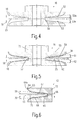
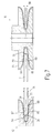
- the grooves of the first guide and the transport wheel are each V-shaped.
- the inner groove height is chosen to be smaller than the height of the thinnest information plate. This ensures that the outer edge of the information plate does not touch the inner edges of the grooves during the loading process. The information plate only touches the grooves in the area of the inclined pressure surfaces.
- the information plate in an ejection position clamps in the grooves of the first and the second guide such that it must be pulled out of the grooves by the hand of an operator with a minimum force of 0.7N.
- Such selected angles of inclination of the pressure surfaces have proven to be particularly advantageous. If the angle of inclination of the pressure surfaces is selected to be greater than 7 ° or 8 °, the normal force which can be applied to the surface of the information plate in the region of the pressure surfaces is very small. If the angle of inclination is selected to be less than 3 ° or 4 °, the loading mechanism becomes very sensitive to tolerances in the thickness of the information plate for a given radial groove depth.
- a further advantageous embodiment of the invention is characterized in that the modulus of elasticity of the surfaces of the pressure surfaces is greater than the modulus of elasticity of the information plate, that the surfaces of the pressure surfaces have such a roughness and the information plate has such a roughness Force is pressed against the pressure surfaces of the groove so that there is a frictional connection between the information plate and the pressure surfaces in the area of the pressure surfaces during the loading process.
- the surface is provided with a certain roughness. Since the modulus of elasticity of the surface of the pressure surface is greater than the modulus of elasticity of the information plate, the surface of the information plate partially engages in the rough surface of the pressure surfaces, so that there is a frictional connection between the surface of the information plate and the pressure surfaces.
- a further advantageous embodiment of the invention is characterized in that. that the base material of the transport wheel is steel and that the steel is covered with a layer of chrome carbide at least in the area of the pressure surfaces.
- the basic contour of the transport wheel can e.g. can be turned from a steel.
- This turned transport wheel made of steel is covered with a layer of chrome carbide in the area of the pressure surfaces.
- HV Vickers hardness
- the elastic modulus of chrome carbide is very large, and values of more than 300 gigascascals can be achieved.
- chromium carbide has very good adhesion to polycarbonate, from which information plates made according to the compact disc standard are made.
- tungsten-carbon-hydrogen layer Due to the great hardness of the tungsten-carbon-hydrogen layer, there is very little wear both on the tungsten-carbon-hydrogen layer and on the surface of the information plate. As a result of the good adhesion between tungsten carbon hydrogen and polycarbonate, high static friction forces occur between the surface of the information plate and the pressure surfaces made of tungsten carbon hydrogen, so that large pull-in forces and holding forces can be applied to the information plate in the direction of the loading level.
- the large elastic modulus of the tungsten-carbon-hydrogen layer ensures that the surface of the information plate partially engages the surface of the tungsten-carbon-hydrogen layer, so that a frictional connection occurs.
- a further advantageous embodiment of the invention is characterized in that the base material of the first guide is steel and that the steel is covered with a layer of chromium carbide or tungsten carbon hydrogen at least in the area of the pressure surfaces.
- the maximum surface roughness R t of the pressure surfaces is in a range between 2 ⁇ m and 15 ⁇ m and that the arithmetic mean roughness R a is in a range between 0.2 ⁇ m and 1.5 ⁇ m.
- the arithmetic mean roughness R a is greater than 1.5 ⁇ m, the surface roughness is distributed too unevenly, and the force that is applied to the surface of the information plate by means of the pressure surfaces is subject to local fluctuations. This can lead to the information plate rolling in unevenly, in particular to stick-and-slip behavior. If the maximum surface roughness R t of the pressure surfaces is greater than 15 ⁇ m, this leads to great wear on the surface of the information plate, and the surface layer of the information plate is abraded. If the maximum surface roughness R t of the pressure surfaces is less than 2 ⁇ m, the static friction between the pressure surfaces and the surface of the information plate becomes very low, so that the force that can be applied to the information plate in the loading plane can become too low.
- the chrome-carbide layer or the tungsten-carbon-hydrogen layer is advantageously vapor-deposited by means of a vapor deposition process.
- a vapor deposition process has the advantage that the chromium carbide or the tungsten carbon hydrogen adapts to the surface structure of the steel. If the steel has the desired surface roughness in the area of the pressure surfaces, this surface roughness is retained by vapor deposition of the chromium-carbide layer or the tungsten-carbon-hydrogen layer.
- a CVD (Chemical Vapor Deposition) process is particularly suitable as a vapor deposition process for the chromium carbide layer and a PVD (Physical Vapor Deposition) process is suitable as a vapor deposition process for the tungsten-carbon-hydrogen layer.
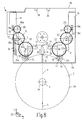
- Fig. 1 shows a first embodiment of a loading mechanism according to the invention in the eject position.
- the loading mechanism shown in FIG. 1 is arranged in a housing 1.
- the loading mechanism serves to retract an information plate 2 on a rectilinear loading path 4 in a first loading direction 5 into the housing 1 or to extend the information plate 2 on the rectilinear loading path 4 against the first loading direction 5.
- the information plate 2 has a circular edge 2a and points a circular positioning hole 3 with an edge 3a.
- the housing 1 has a front wall 6a, a rear wall 6b, side walls 6c and 6d as well as a base plate 6e and a housing cover 6f.
- Two stops 34 and 35 are arranged on the rear wall 6b of the housing 1.
- the information plate 2 is from the hand of the operator with the groove 13 of the support segment 12 and the groove 18 of the Transport wheels 16 have been engaged.
- the operator grips the information plate 2 at the edge 2a of the information plate 2 and at the edge 3a of the positioning hole 3.
- the information plate 2 is held in this way from the ejection position shown in FIG. 1 to the intermediate position shown in FIG. 2.
- the first pivot arm 7 is pivoted about the pivot axis 8 and the second pivot arm 9 about the pivot axis 10.
- the required pivoting force is applied by the operator.
- the information plate 2 is guided laterally on one side by the groove 13 of the support segment 12 and on the other side by the groove 18 of the transport wheel 16. The surface of the information plate 2 is not touched by the operator's hand.
- the motor 19 is controlled by a switch (not shown), and the charging mechanism carries out the further charging process automatically.
- the switch is e.g. a mechanical switch or an optical switch (light barrier) can be used. It is also possible that the engine is started earlier.
- a drive mechanism not shown, is switched on in a manner not shown in detail, which acts on the first pivot arm 7 in such a way that it rotates clockwise around the pivot axis 8 pivots, and which acts on the second pivot arm 9 such that it pivots counterclockwise about the pivot axis 10.
- the groove 18 of the transport wheel 16 and the groove 13 of the support segment 12 are brought out of engagement with the edge 2a of the information plate 2.
- the information plate 2 is also no longer guided by the lower contact surface 86a of the auxiliary guide 36.
- the transport wheel 16 has a base element 72 made of steel.
- the basic contour 55 of the base element 72 can be produced from a raw steel, for example by turning.
- the steel base contour 55 of the base element 72 is covered with a layer 56 of chrome carbide.
- the chromium carbide layer 56 can be vapor-deposited, for example, by means of a vapor deposition process.
- a possible vapor deposition process is the CVD process (Chemical Vapor Deposition).
- the vapor-deposited chrome-carbide layer 56 runs parallel to the basic contour 55.
- the circumferential groove 18 has an inner edge 57 with an inner groove height 58.
Landscapes
- Feeding And Guiding Record Carriers (AREA)
- Micro-Organisms Or Cultivation Processes Thereof (AREA)
Priority Applications (1)
| Application Number | Priority Date | Filing Date | Title |
|---|---|---|---|
| EP19970201328 EP0805445B1 (fr) | 1996-05-02 | 1997-05-02 | Mécanisme de chargement pour charger et décharger un disque d'information d'un appareil technique d'information |
Applications Claiming Priority (5)
| Application Number | Priority Date | Filing Date | Title |
|---|---|---|---|
| EP96201215A EP0742558B1 (fr) | 1995-05-06 | 1996-05-02 | Mécanisme de chargement |
| EP96201215 | 1996-05-02 | ||
| DE19626759 | 1996-07-03 | ||
| DE1996126759 DE19626759A1 (de) | 1996-05-02 | 1996-07-03 | Lademechanismus zum Be- und Entladen eines informationstechnischen Gerätes mit einer Informationsplatte |
| EP19970201328 EP0805445B1 (fr) | 1996-05-02 | 1997-05-02 | Mécanisme de chargement pour charger et décharger un disque d'information d'un appareil technique d'information |
Publications (3)
| Publication Number | Publication Date |
|---|---|
| EP0805445A2 true EP0805445A2 (fr) | 1997-11-05 |
| EP0805445A3 EP0805445A3 (fr) | 1998-02-04 |
| EP0805445B1 EP0805445B1 (fr) | 2002-02-13 |
Family
ID=27216411
Family Applications (1)
| Application Number | Title | Priority Date | Filing Date |
|---|---|---|---|
| EP19970201328 Expired - Lifetime EP0805445B1 (fr) | 1996-05-02 | 1997-05-02 | Mécanisme de chargement pour charger et décharger un disque d'information d'un appareil technique d'information |
Country Status (1)
| Country | Link |
|---|---|
| EP (1) | EP0805445B1 (fr) |
Family Cites Families (7)
| Publication number | Priority date | Publication date | Assignee | Title |
|---|---|---|---|---|
| JPS5975461A (ja) * | 1982-10-20 | 1984-04-28 | Sanyo Electric Co Ltd | デイスク装着装置 |
| US4567584A (en) * | 1983-06-13 | 1986-01-28 | Kabushiki Kaisha Toshiba | Autochanger type disc player |
| BE901937A (fr) * | 1985-03-14 | 1985-07-01 | Staar Sa | Dispositif d'insertion et d'ejection automatique de supports d'informations. |
| DE3732918A1 (de) * | 1987-09-30 | 1989-04-20 | Thomson Brandt Gmbh | Lade- und entladevorrichtung eines cd-geraetes |
| JPH0624033Y2 (ja) * | 1988-09-05 | 1994-06-22 | パイオニア株式会社 | フロントローディングディスクプレーヤ |
| US5255255A (en) * | 1990-11-27 | 1993-10-19 | Matsushita Electric Industrial, Co., Ltd. | Disk loading device |
| KR920022259A (ko) * | 1991-05-02 | 1992-12-19 | 오오가 노리오 | 디스크 로우딩 장치 |
-
1997
- 1997-05-02 EP EP19970201328 patent/EP0805445B1/fr not_active Expired - Lifetime
Also Published As
| Publication number | Publication date |
|---|---|
| EP0805445B1 (fr) | 2002-02-13 |
| EP0805445A3 (fr) | 1998-02-04 |
Similar Documents
| Publication | Publication Date | Title |
|---|---|---|
| EP0742558B1 (fr) | Mécanisme de chargement | |
| DE2839277C3 (de) | Einrichtung für das Zentrieren eines kreisscheibenförmigen Aufzeichnungsträgers an der Drehachse eines Aufzeichnungsgerätes | |
| DE69316791T2 (de) | Begrenzung mit magnetischer Raste für optimalen Gebrauch der Plattenoberfläche | |
| DE69023619T2 (de) | Plattenspieler mit Detektionseinheit. | |
| EP0671743B1 (fr) | Dispositif de maintien pour support d'information en forme de disque | |
| DE2413218A1 (de) | Leseeinrichtung fuer aufgezeichnete informationen | |
| DE3713389A1 (de) | Bernoulli-platte in einer kassette | |
| DE2828964C2 (de) | Vorrichtung zum selbsttätigen Reinigen des Tonkopfes eines Bandkassettengeräts | |
| DE69309389T2 (de) | Vorrichtung zum Messen des Biegewinkels eines Bleches | |
| DE2550633B2 (fr) | ||
| DE3712596C2 (fr) | ||
| DE2735380A1 (de) | Gehaeuse fuer ein plattenfoermiges aufzeichnungsmedium und vorrichtung zu dessen halterung an einem aufnahme- und wiedergabegeraet | |
| EP0805445B1 (fr) | Mécanisme de chargement pour charger et décharger un disque d'information d'un appareil technique d'information | |
| DE3131971C2 (de) | Mechanismus zum Justieren der Drehebene eines Plattentellers in einem Wiedergabegerät für ein sich drehendes Aufzeichnungsmedium | |
| EP0061766B1 (fr) | Suspension pour moteur d'entraînement de bande, pivotant dans un appareil à cassette de bande magnétique | |
| DE3003972C2 (de) | Drehmagnetkopf zur Halterung von Magnetköpfen | |
| DE3725692A1 (de) | Bremsvorrichtung | |
| DE19626759A1 (de) | Lademechanismus zum Be- und Entladen eines informationstechnischen Gerätes mit einer Informationsplatte | |
| EP0182025B1 (fr) | Dispositif pour rabattre au moins une tête de transducteur électromagnétique | |
| DE3912493C2 (fr) | ||
| DE60124306T2 (de) | Aufzeichnungs- und/oder wiedergabegerät für optische aufzeichnungsmedien | |
| DE2407277A1 (de) | Drehbarer tonkopf fuer tonbandgeraete | |
| DE69715683T2 (de) | Linearantriebsvorrichtung | |
| DE2641296C2 (de) | Vorrichtung zum Abtasten von spiralförmig aufgezeichneten Informationen mit einem federbelasteten Abtastarm | |
| DE2751390C3 (de) | Winkellagen-Einstellvorrichtung, insbesondere für, optische Messungen |
Legal Events
| Date | Code | Title | Description |
|---|---|---|---|
| PUAI | Public reference made under article 153(3) epc to a published international application that has entered the european phase |
Free format text: ORIGINAL CODE: 0009012 |
|
| AK | Designated contracting states |
Kind code of ref document: A2 Designated state(s): DE FR GB IT |
|
| PUAL | Search report despatched |
Free format text: ORIGINAL CODE: 0009013 |
|
| AK | Designated contracting states |
Kind code of ref document: A3 Designated state(s): DE FR GB IT |
|
| 17P | Request for examination filed |
Effective date: 19980804 |
|
| RAP3 | Party data changed (applicant data changed or rights of an application transferred) |
Owner name: KONINKLIJKE PHILIPS ELECTRONICS N.V. Owner name: PHILIPS CORPORATE INTELLECTUAL PROPERTY GMBH |
|
| 17Q | First examination report despatched |
Effective date: 19991229 |
|
| GRAG | Despatch of communication of intention to grant |
Free format text: ORIGINAL CODE: EPIDOS AGRA |
|
| GRAG | Despatch of communication of intention to grant |
Free format text: ORIGINAL CODE: EPIDOS AGRA |
|
| GRAH | Despatch of communication of intention to grant a patent |
Free format text: ORIGINAL CODE: EPIDOS IGRA |
|
| GRAH | Despatch of communication of intention to grant a patent |
Free format text: ORIGINAL CODE: EPIDOS IGRA |
|
| GRAA | (expected) grant |
Free format text: ORIGINAL CODE: 0009210 |
|
| REG | Reference to a national code |
Ref country code: GB Ref legal event code: IF02 |
|
| RIN1 | Information on inventor provided before grant (corrected) |
Inventor name: GIELKENS, MARC Inventor name: NOORDHOEK, HARALD Inventor name: SCHOLZ, THOMAS |
|
| AK | Designated contracting states |
Kind code of ref document: B1 Designated state(s): DE FR GB IT |
|
| REF | Corresponds to: |
Ref document number: 59706354 Country of ref document: DE Date of ref document: 20020321 |
|
| GBT | Gb: translation of ep patent filed (gb section 77(6)(a)/1977) |
Effective date: 20020412 |
|
| ET | Fr: translation filed | ||
| RAP2 | Party data changed (patent owner data changed or rights of a patent transferred) |
Owner name: KONINKLIJKE PHILIPS ELECTRONICS N.V. Owner name: PHILIPS CORPORATE INTELLECTUAL PROPERTY GMBH |
|
| PLBE | No opposition filed within time limit |
Free format text: ORIGINAL CODE: 0009261 |
|
| STAA | Information on the status of an ep patent application or granted ep patent |
Free format text: STATUS: NO OPPOSITION FILED WITHIN TIME LIMIT |
|
| 26N | No opposition filed |
Effective date: 20021114 |
|
| PG25 | Lapsed in a contracting state [announced via postgrant information from national office to epo] |
Ref country code: IT Free format text: LAPSE BECAUSE OF NON-PAYMENT OF DUE FEES;WARNING: LAPSES OF ITALIAN PATENTS WITH EFFECTIVE DATE BEFORE 2007 MAY HAVE OCCURRED AT ANY TIME BEFORE 2007. THE CORRECT EFFECTIVE DATE MAY BE DIFFERENT FROM THE ONE RECORDED. Effective date: 20050502 |
|
| PGFP | Annual fee paid to national office [announced via postgrant information from national office to epo] |
Ref country code: DE Payment date: 20070713 Year of fee payment: 11 |
|
| PGFP | Annual fee paid to national office [announced via postgrant information from national office to epo] |
Ref country code: GB Payment date: 20070522 Year of fee payment: 11 |
|
| PGFP | Annual fee paid to national office [announced via postgrant information from national office to epo] |
Ref country code: FR Payment date: 20070529 Year of fee payment: 11 |
|
| GBPC | Gb: european patent ceased through non-payment of renewal fee |
Effective date: 20080502 |
|
| REG | Reference to a national code |
Ref country code: FR Ref legal event code: ST Effective date: 20090119 |
|
| PG25 | Lapsed in a contracting state [announced via postgrant information from national office to epo] |
Ref country code: FR Free format text: LAPSE BECAUSE OF NON-PAYMENT OF DUE FEES Effective date: 20080602 Ref country code: DE Free format text: LAPSE BECAUSE OF NON-PAYMENT OF DUE FEES Effective date: 20081202 |
|
| PG25 | Lapsed in a contracting state [announced via postgrant information from national office to epo] |
Ref country code: GB Free format text: LAPSE BECAUSE OF NON-PAYMENT OF DUE FEES Effective date: 20080502 |