EP0805525B1 - Dispositif pour le montage flottant d'un connecteur électrique à un panneau - Google Patents
Dispositif pour le montage flottant d'un connecteur électrique à un panneau Download PDFInfo
- Publication number
- EP0805525B1 EP0805525B1 EP97106695A EP97106695A EP0805525B1 EP 0805525 B1 EP0805525 B1 EP 0805525B1 EP 97106695 A EP97106695 A EP 97106695A EP 97106695 A EP97106695 A EP 97106695A EP 0805525 B1 EP0805525 B1 EP 0805525B1
- Authority
- EP
- European Patent Office
- Prior art keywords
- panel
- housing
- opening
- connector
- mounting system
- Prior art date
- Legal status (The legal status is an assumption and is not a legal conclusion. Google has not performed a legal analysis and makes no representation as to the accuracy of the status listed.)
- Expired - Lifetime
Links
- 230000037431 insertion Effects 0.000 claims description 16
- 238000003780 insertion Methods 0.000 claims description 16
- 239000000463 material Substances 0.000 claims description 4
- 230000013011 mating Effects 0.000 description 14
- 230000000295 complement effect Effects 0.000 description 2
- 239000003989 dielectric material Substances 0.000 description 1
- 238000009434 installation Methods 0.000 description 1
Images


Classifications
-
- H—ELECTRICITY
- H01—ELECTRIC ELEMENTS
- H01R—ELECTRICALLY-CONDUCTIVE CONNECTIONS; STRUCTURAL ASSOCIATIONS OF A PLURALITY OF MUTUALLY-INSULATED ELECTRICAL CONNECTING ELEMENTS; COUPLING DEVICES; CURRENT COLLECTORS
- H01R13/00—Details of coupling devices of the kinds covered by groups H01R12/70 or H01R24/00 - H01R33/00
- H01R13/62—Means for facilitating engagement or disengagement of coupling parts or for holding them in engagement
- H01R13/629—Additional means for facilitating engagement or disengagement of coupling parts, e.g. aligning or guiding means, levers, gas pressure electrical locking indicators, manufacturing tolerances
- H01R13/631—Additional means for facilitating engagement or disengagement of coupling parts, e.g. aligning or guiding means, levers, gas pressure electrical locking indicators, manufacturing tolerances for engagement only
- H01R13/6315—Additional means for facilitating engagement or disengagement of coupling parts, e.g. aligning or guiding means, levers, gas pressure electrical locking indicators, manufacturing tolerances for engagement only allowing relative movement between coupling parts, e.g. floating connection
-
- H—ELECTRICITY
- H01—ELECTRIC ELEMENTS
- H01R—ELECTRICALLY-CONDUCTIVE CONNECTIONS; STRUCTURAL ASSOCIATIONS OF A PLURALITY OF MUTUALLY-INSULATED ELECTRICAL CONNECTING ELEMENTS; COUPLING DEVICES; CURRENT COLLECTORS
- H01R13/00—Details of coupling devices of the kinds covered by groups H01R12/70 or H01R24/00 - H01R33/00
- H01R13/73—Means for mounting coupling parts to apparatus or structures, e.g. to a wall
- H01R13/74—Means for mounting coupling parts in openings of a panel
Definitions
- This invention generally relates to the art of electrical connectors and, particularly, to an electrical connector floating panel mounting system.
- An electrical connector pannel mounting system according to the preamble of claim 1 is known from US-A-5,407,363.
- Panel mounted electrical connectors usually include a non-conductive or dielectric housing having a plurality of electrically conductive terminals mounted therein. the housing also includes means for mounting the connector to a panel.
- the panel mounted connector is mateable with other electrical apparatus, such as another connector, which, in turn, may be mounted to a second panel, a circuit board, a cable or discrete wires.
- the mating of a panel mounted electrical connector to another connector or circuit component is carried out under "blind mating" conditions such that precise alignment of the panel mounted connector with the other connector or circuit component cannot be assured.
- Blind mating of panel mounted connectors may occur in a wide variety of applications including components of copying machines, computer equipment, telecommunications equipment and like applications. Attempts to forcibly blind mate improperly aligned electrical connectors can damage the housings of the connectors, the fragile terminals of the housings or the panels to which the connectors are mounted. Improper alignment also may prevent complete mating, thereby negatively affecting the quality of the electrical connection.
- the present invention is directed to providing such a panel mounted electrical connector which not only is provided with a floating action but which is locked in its floating, mounted position, all by extremely simple means.
- An object, therefore, of the invention is to provide a new and improved floating panel mounting system for electrical connectors of the character described.
- the system includes a panel having a given thickness between two surfaces and including a first opening formed with at least one radially extending locating portion and a second opening spaced from the first opening.
- a connector includes a dielectric housing insertable from one surface of the panel along an axis to an insertion position into the first opening in the panel.
- the housing has at least one radially extending locating flange for passing through the locating portion of the first opening as the housing is inserted thereinto.
- the housing has at least one radially extending stop flange spaced axially and angularly from the locating flange for abutting the one surface of the panel when the locating flange clears the opposite surface of the panel.
- the housing is rotatable about the axis from its insertion position to a mounted position whereat the locating flange can abut the opposite surface of the panel to prevent axial removal of the housing back out of the first opening.
- the cross-sectional configuration of the housing is smaller than the first opening when in the mounted position to provide radial floating of the connector relative to the panel.
- the invention contemplates that the housing have a locking arm projecting radially therefrom.
- the locking arm includes a locking protrusion for engagement in the second opening in the panel when the housing is in its mounted position.
- the engagement of the locking protrusion in the second opening prevents rotation of the connector from the mounted position back to the insertion position.
- the second opening is larger than the locking protrusion to allow for the aforesaid radial floating of the connector relative to the panel.
- the second opening in the panel is circular, whereby the radial floating action of the connector is omni-directional.
- the locking protrusion preferably is generally cylindrical.
- the housing is molded of plastic material, and the locking arm is molded integrally therewith.
- the locking arm thereby is flexible such that the locking protrusion comprises a detent adapted for snapping into the second opening in the panel automatically when the housing is rotated to its mounted position to lock the housing thereat.
- the panel mounting system of the invention includes an electrical connector, generally designated 10, which has a dielectric housing 12 with a forwardly projecting mating portion 14.
- the mating portion is insertable through a panel (described hereinafter) for mating with the mating portion of a complementary connector on the opposite side of the panel.
- Housing 12 of connector 10 includes a pair of diametrically disposed, radially outwardly extending locating flanges 16.
- the locating flanges are spaced axially and angularly from a pair of diametrically disposed, radially outwardly extending stop flanges 18.
- the stop flanges are spaced axially from the locating flanges by a distance "D" shown in Figure 1 and define a panel receiving region therebetween.
- the stop flanges are larger, in an angular or circumferential direction, than the locating flanges.
- a locking arm 20 projects radially outwardly of the housing and includes a forwardly projecting integral locking protrusion 22.
- the locking arm projects outwardly from one of the stop flanges 18 which, in turn, projects outwardly of the housing.
- Housing 12 including mating portion 14, locating flanges 16, stop flanges 18, locking arm 20 and locking protrusion 22 all are unitarily molded of dielectric material, such as plastic or the like.
- Housing 12 particularly mating portion 14 of the housing, has a plurality of terminals (not shown) mounted therein which interengage with appropriate terminals of the complementary mating connector.
- mating portion 14 can take a wide variety of configurations and, consequently, the mating portion and the terminals are not described in detail herein.
- the housing is circular or cylindrical in cross-sectional configuration.
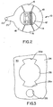
- the mounting system of the invention includes a cooperating panel 24 having a given thickness between two surfaces and including a larger, first circular opening 26 and a smaller, second circular opening 28.
- a pair of diametrically disposed locating portions or slots 26a extend radially outwardly of first opening 26.
- Figure 4 shows electrical connector 10 in an insertion position relative to panel 24.
- panel 24 has a given thickness between two surfaces.
- One surface can be considered the insertion surface or side of the panel and is the back side of the panel as viewed in the drawings.
- the opposite surface or side of the panel is shown at 30 and, of course, is the surface of the panel opposite the insertion surface or side.
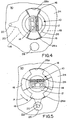
- the connector is mounted to the panel by first inserting housing 12 through first opening 26 as shown in Figure 4.
- the housing is inserted along an axis to the insertion position shown.
- radially extending locating flanges 16 move through locating portions 26a of the first opening until stop flanges 18 abut the insertion surface of the panel.
- locking arm 20 and locking protrusion 22 are spaced angular approximately 90° from second opening 28 in the panel.
- locking arm 20 is generally flexible. Consequently, locking protrusion 22 comprises a detent which is adapted for snapping into second opening 28 in the panel automatically when the housing is rotated from its insertion position shown in Figure 4, in the direction of arrow "A" to its mounted or lock position shown in Figure 5.
- Figure 4 best shows the degree that circular opening 26 in panel 24 is larger than cylindrical housing 12 of connector 10.
- Figure 5 best shows the degree that circular second opening 28 is larger than locking protrusion 22. Therefore, it readily can be understood that the combination of these two enlarged openings allow for rotational and lateral floating of the connector relative to the panel. In other words, housing 12 can move considerably in a rotational and lateral direction within enlarged first opening 26, and locking protrusion 22 can move considerably in a rotational and lateral direction within enlarged second opening 28.
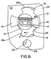
- Figures 6-8 show various positions of connector 10 relative to panel 24 while the connector remains in its mounted position.
- Figure 6 shows that connector 10 has moved upwardly (as viewed in the drawing) in the direction of arrow "B" until housing 12 has reached its upper limit position within first opening 26.
- Locking protrusion 22 also can be seen to have moved upwardly to its limit position within second opening 28.
- Figure 7 shows that connector 10 has moved considerably downwardly in the direction of arrow "C" relative to panel 24 until housing 12 has reached its downward limit position as viewed in the drawing within first aperture 26. Locking protrusion 22 also has been moved downwardly to its limit position within second opening 28.
- Figure 8 shows that connector 10 has moved considerably toward the left as viewed in the drawing, in the direction of arrow "E" relative to panel 24. It can be seen that housing 12 has moved to its left-most limit position within first opening 26, and, likewise, locking protrusion 22 has moved to its left-most limit position within second opening 28. Of course, the connector, the housing and the locking protrusion can move the same distance toward the right as viewed in the drawing, relative to panel 24, opposite the direction of arrow "E".
- Figures 6-8 clearly illustrate the wide range of lateral floating action that is afforded between connector 10 and panel 24 while the connector still remains locked in its mounted position.
- first opening 26 and second opening 28 being circular
- housing 12 and locking protrusion 22 being cylindrical
- an infinite number of omni-directional floating positions including partial rotation of the housing are afforded between the housing and the panel within the limit positions defined above in relation to Figures 6-8.
Landscapes
- Connector Housings Or Holding Contact Members (AREA)
Claims (6)
- Système de montage d'un connecteur électrique sur un panneau, qui comprend un panneau (24) ayant une épaisseur donnée entre deux surfaces, une première ouverture (26) formée de facon à comporter au moins une partie (26a) de positionnement s'étendant radialement et une seconde ouverture (28), et qui comprend en outre un connecteur électrique comportant:un boitier diélectrique (12) pouvant etre inséré depuis une surface du panneau (24) suivant un axe jusque dans une position d'insertion dans la première ouverture (26) dans le panneau, le boitier ayant au moins une bride (16) de positionnement s'étendant radialement, destinée à passer à travers la partie (26a) de positionnement de la première ouverture pendant que le boitier est insére dans celle-ci, et au moins une bride (18) d'arret s'étendant radialement, espacée axialement et angulairement de la bride (16) de positionnement pour venir en appui sur la première surface du panneau lorsque la bride de positionnement se dégage de la surface opposée (30) du panneau, le boitier pouvant etre tourné autour dudit axe depuis sa position d'insertion jusqu'à une postition de montage dans laquelle la bride (16) de positionnement peut s'appliquer en appui sur la surface opposée (30 du panneau (24) afin d'empecher tout enlèvement axial du boitier en ressortant de la première ouverture, et la configuration de la section transversale du boitier étant plus petite que la première ouverture (26) et, lorsqu'il est dans la position montée, permettant un flottement de rotation et latéral du connecteur par rapport au panneau; caractérisé en ce queun bras (20) de verrouillage faisant saillie radialement du boitier comprend une saillie (22) de verrouillage destinée à s'engager dans la seconde ouverture (28) du panneau (24) lorsque le boitier est dans sa position montée et à empecher toute rotation du connecteur en retour de la position montée vers la position d'insertion, la seconde ouverture (28) étant plus grande que la saillie de verrouillage (22) pour permettre ledit flottement de rotation et latéral du connecteur par rapport au panneau et la seconde ouverture étant espacée de la première ouverture.
- Système de montage d'un connecteur électrique sur un panneau selon la revendication 1, dans lequel ladite seconde ouverture (28) dans le panneau (24) est circulaire afin de faciliter une action flottante de rotation et latérale omnidirectionnelle du connecteur.
- Système de montage d'un connecteur électrique sur un panneau selon la revendication 2, dan lequel ladite saillie (22) de verrouillage est globalement cylindrique.
- Système de montage d'un connecteur électrique sur un panneau selon la revendication 1, dans lequel ledit boitier (12) est moulé en matière plastique et ledit bras (20) de verrouillage est moulé d'une seule pièce avec lui.
- Système de montage d'un connecteur électrique sur un panneau selon la revendication 1, dans lequel ledit bras (20) de verrouillage est flexible de facon que ladite saillie (22) de verrouillage comporte une pièce d'arret concue pour s'encliqueter dans la seconde ouverture (28) dans le panneau, automatiquement lorsque le boitier (12) est tourné vers sa position montée pour y verrouiller le boitier.
- Système de montage d'un connecteur électrique sur un panneau selon la revendication 5, dans lequel ledit boitier (12) est moulé en matière plastique et ledit bras (20) de verrouillage est moulé d'une seule pièce avec lui.
Applications Claiming Priority (2)
| Application Number | Priority Date | Filing Date | Title |
|---|---|---|---|
| US08/642,007 US5772469A (en) | 1996-05-02 | 1996-05-02 | Floating panel mounting system for electrical connectors |
| US642007 | 1996-05-02 |
Publications (3)
| Publication Number | Publication Date |
|---|---|
| EP0805525A2 EP0805525A2 (fr) | 1997-11-05 |
| EP0805525A3 EP0805525A3 (fr) | 1998-09-09 |
| EP0805525B1 true EP0805525B1 (fr) | 2004-09-22 |
Family
ID=24574779
Family Applications (1)
| Application Number | Title | Priority Date | Filing Date |
|---|---|---|---|
| EP97106695A Expired - Lifetime EP0805525B1 (fr) | 1996-05-02 | 1997-04-23 | Dispositif pour le montage flottant d'un connecteur électrique à un panneau |
Country Status (3)
| Country | Link |
|---|---|
| US (1) | US5772469A (fr) |
| EP (1) | EP0805525B1 (fr) |
| DE (1) | DE69730772D1 (fr) |
Families Citing this family (19)
| Publication number | Priority date | Publication date | Assignee | Title |
|---|---|---|---|---|
| US5984721A (en) * | 1997-04-08 | 1999-11-16 | Whitaker Corporation | Panel mount connector with twist lock |
| DE29808526U1 (de) * | 1998-05-12 | 1999-09-23 | Robert Bosch Gmbh, 70469 Stuttgart | Elektrischer Steckverbinder |
| DE29808527U1 (de) * | 1998-05-12 | 1999-09-23 | Robert Bosch Gmbh, 70469 Stuttgart | Elektrischer Steckverbinder |
| US6312285B1 (en) * | 1999-02-25 | 2001-11-06 | Molex Incorporated | Panel mounting system for electrical connectors |
| US6095854A (en) * | 1999-04-12 | 2000-08-01 | Molex Incorporated | Panel mounting system for electrical connectors |
| JP3566605B2 (ja) * | 1999-12-03 | 2004-09-15 | 矢崎総業株式会社 | コネクタ支持機構 |
| US6450834B1 (en) | 2001-12-10 | 2002-09-17 | Molex Incorporated | Panel mounting system for electrical connectors |
| US6716059B1 (en) * | 2003-04-28 | 2004-04-06 | Molex Incorporated | Panel mounted electrical connector |
| US7431610B2 (en) * | 2005-01-21 | 2008-10-07 | Leviton Manufacturing Co., Inc. | Cable slack manager system and method |
| FR2888677B1 (fr) * | 2005-07-12 | 2010-12-10 | Radiall Sa | Ensemble de connexion electrique |
| US7090533B1 (en) * | 2005-08-25 | 2006-08-15 | Sumitomo Wiring Systems, Ltd. | Twist lock panel-mounted connector |
| US8014165B2 (en) | 2007-08-03 | 2011-09-06 | Tyco Electronics Corporation | Panel mount connector |
| US7658642B2 (en) * | 2007-09-07 | 2010-02-09 | Delphi Technologies, Inc. | Molded plastic pass through article with flexible transverse lock arms |
| JP6225444B2 (ja) * | 2013-03-26 | 2017-11-08 | 船井電機株式会社 | 同調回路 |
| ITPI20130044A1 (it) * | 2013-05-24 | 2014-11-25 | Marco Ariani | Struttura perfezionata di supporto per articoli di vario genere |
| US9443671B2 (en) * | 2014-09-23 | 2016-09-13 | Whirlpool Corporation | Apparatus and method to pass electrical signals through a refrigerator cabinet liner |
| WO2019143993A1 (fr) * | 2018-01-19 | 2019-07-25 | Lutron Electronics Co., Inc. | Boîtiers muraux fournissant un support réglable destiné à un dispositif de commande, appareils, et dispositif électrique |
| USD1101697S1 (en) | 2023-06-07 | 2025-11-11 | Molex, Llc | Electric connector |
| USD1103121S1 (en) * | 2023-06-07 | 2025-11-25 | Molex, Llc | Electric connector |
Family Cites Families (7)
| Publication number | Priority date | Publication date | Assignee | Title |
|---|---|---|---|---|
| US3912355A (en) * | 1971-08-20 | 1975-10-14 | Trw Inc | Plug and socket connections |
| US4029953A (en) * | 1975-09-22 | 1977-06-14 | General Motors Corporation | Twist-lock lamp socket locking means |
| US4820180A (en) * | 1988-06-09 | 1989-04-11 | Molex Incorporated | Floating panel mount for electrical connector |
| US5017151A (en) * | 1990-10-05 | 1991-05-21 | Molex Incorporated | Floating panel mount for electrical connectors |
| US5127852A (en) * | 1990-10-24 | 1992-07-07 | Amp Incorporated | Mounting device for electrical connectors |
| US5338226A (en) * | 1993-05-14 | 1994-08-16 | Molex Incorporated | Panel mounting system for electrical connectors |
| US5407363A (en) * | 1994-03-11 | 1995-04-18 | Molex Incorporated | Floating panel mounting system for electrical connectors |
-
1996
- 1996-05-02 US US08/642,007 patent/US5772469A/en not_active Expired - Lifetime
-
1997
- 1997-04-23 EP EP97106695A patent/EP0805525B1/fr not_active Expired - Lifetime
- 1997-04-23 DE DE69730772T patent/DE69730772D1/de not_active Expired - Lifetime
Also Published As
| Publication number | Publication date |
|---|---|
| EP0805525A3 (fr) | 1998-09-09 |
| DE69730772D1 (de) | 2004-10-28 |
| EP0805525A2 (fr) | 1997-11-05 |
| US5772469A (en) | 1998-06-30 |
Similar Documents
| Publication | Publication Date | Title |
|---|---|---|
| US5888093A (en) | Floating panel mounting system for electrical connectors | |
| EP0805525B1 (fr) | Dispositif pour le montage flottant d'un connecteur électrique à un panneau | |
| EP0671786B1 (fr) | Dispositif pour le montage flottant d'un connecteur électrique à un panneau | |
| EP0441477B1 (fr) | Assemblage de connecteur électrique montable de façon flottante dans un tableau | |
| US6450834B1 (en) | Panel mounting system for electrical connectors | |
| US4477022A (en) | Polarizing and latch arrangement for an electrical connector | |
| EP0706237B1 (fr) | Connecteur électrique avec dispositif à assurer la position des terminaux et moyens de guidage d'un connecteur complémentaire | |
| US7074087B2 (en) | Cable connector system for shielded cable | |
| EP3930114B1 (fr) | Connecteur coaxial limitant l'affaissement | |
| KR20030051403A (ko) | 직각형 인쇄회로기판 커넥터 장치, 그 제조방법 및제조물품들 | |
| JP2007123273A (ja) | 電気コネクタ組立体 | |
| EP0125786A2 (fr) | Ensemble de connecteur électrique | |
| EP0624932B1 (fr) | Système de montage sur un panneau pour connections électriques | |
| EP0994533A1 (fr) | Système de connecteur avec mécanisme de codage | |
| EP0732778B1 (fr) | Connecteur électrique avec tige de montage | |
| US12230922B2 (en) | Bi-directional header for multi-direction connector mating | |
| EP0901189B1 (fr) | Système de montage d'un ensemble de connexion électrique | |
| US4921431A (en) | Connector adapter assembly | |
| EP0438280B1 (fr) | Eléments de fixation pour l'assemblage movible d'un connecteur électrique sur panneaux | |
| US4867714A (en) | Pin and socket terminal | |
| EP0779676B1 (fr) | Connecteur pour un câble coaxial | |
| EP0618645B1 (fr) | Dispositif pour fixer la position des pièces de contact des connecteurs électriques | |
| EP0560317B1 (fr) | Assemblage de connecteur électrique avec moyens d'alignement/ guidage amélioré | |
| EP1482600B1 (fr) | Boîtier de branchement de câble | |
| US20250337203A1 (en) | Coaxial connector |
Legal Events
| Date | Code | Title | Description |
|---|---|---|---|
| PUAI | Public reference made under article 153(3) epc to a published international application that has entered the european phase |
Free format text: ORIGINAL CODE: 0009012 |
|
| AK | Designated contracting states |
Kind code of ref document: A2 Designated state(s): DE FR GB IT |
|
| PUAL | Search report despatched |
Free format text: ORIGINAL CODE: 0009013 |
|
| AK | Designated contracting states |
Kind code of ref document: A3 Designated state(s): DE FR GB IT |
|
| 17P | Request for examination filed |
Effective date: 19990225 |
|
| GRAP | Despatch of communication of intention to grant a patent |
Free format text: ORIGINAL CODE: EPIDOSNIGR1 |
|
| GRAS | Grant fee paid |
Free format text: ORIGINAL CODE: EPIDOSNIGR3 |
|
| GRAA | (expected) grant |
Free format text: ORIGINAL CODE: 0009210 |
|
| RIN1 | Information on inventor provided before grant (corrected) |
Inventor name: FRY, RUPERT J. Inventor name: POLGAR, GARY E. |
|
| AK | Designated contracting states |
Kind code of ref document: B1 Designated state(s): DE FR GB IT |
|
| PG25 | Lapsed in a contracting state [announced via postgrant information from national office to epo] |
Ref country code: IT Free format text: LAPSE BECAUSE OF FAILURE TO SUBMIT A TRANSLATION OF THE DESCRIPTION OR TO PAY THE FEE WITHIN THE PRE;WARNING: LAPSES OF ITALIAN PATENTS WITH EFFECTIVE DATE BEFORE 2007 MAY HAVE OCCURRED AT ANY TIME BEFORE 2007. THE CORRECT EFFECTIVE DATE MAY BE DIFFERENT FROM THE ONE RECORDED.SCRIBED TIME-LIMIT Effective date: 20040922 Ref country code: FR Free format text: LAPSE BECAUSE OF FAILURE TO SUBMIT A TRANSLATION OF THE DESCRIPTION OR TO PAY THE FEE WITHIN THE PRESCRIBED TIME-LIMIT Effective date: 20040922 |
|
| REG | Reference to a national code |
Ref country code: GB Ref legal event code: FG4D |
|
| REF | Corresponds to: |
Ref document number: 69730772 Country of ref document: DE Date of ref document: 20041028 Kind code of ref document: P |
|
| PG25 | Lapsed in a contracting state [announced via postgrant information from national office to epo] |
Ref country code: DE Free format text: LAPSE BECAUSE OF FAILURE TO SUBMIT A TRANSLATION OF THE DESCRIPTION OR TO PAY THE FEE WITHIN THE PRESCRIBED TIME-LIMIT Effective date: 20041223 |
|
| PGFP | Annual fee paid to national office [announced via postgrant information from national office to epo] |
Ref country code: FR Payment date: 20050401 Year of fee payment: 9 |
|
| PLBE | No opposition filed within time limit |
Free format text: ORIGINAL CODE: 0009261 |
|
| STAA | Information on the status of an ep patent application or granted ep patent |
Free format text: STATUS: NO OPPOSITION FILED WITHIN TIME LIMIT |
|
| 26N | No opposition filed |
Effective date: 20050623 |
|
| EN | Fr: translation not filed | ||
| PGFP | Annual fee paid to national office [announced via postgrant information from national office to epo] |
Ref country code: GB Payment date: 20060424 Year of fee payment: 10 |
|
| GBPC | Gb: european patent ceased through non-payment of renewal fee |
Effective date: 20070423 |
|
| PG25 | Lapsed in a contracting state [announced via postgrant information from national office to epo] |
Ref country code: GB Free format text: LAPSE BECAUSE OF NON-PAYMENT OF DUE FEES Effective date: 20070423 |