EP0805617B1 - Integrated terminal board-filter assembly, particularly for electric household appliances - Google Patents
Integrated terminal board-filter assembly, particularly for electric household appliances Download PDFInfo
- Publication number
- EP0805617B1 EP0805617B1 EP97107101A EP97107101A EP0805617B1 EP 0805617 B1 EP0805617 B1 EP 0805617B1 EP 97107101 A EP97107101 A EP 97107101A EP 97107101 A EP97107101 A EP 97107101A EP 0805617 B1 EP0805617 B1 EP 0805617B1
- Authority
- EP
- European Patent Office
- Prior art keywords
- bracket
- main body
- terminal board
- filter assembly
- casing
- Prior art date
- Legal status (The legal status is an assumption and is not a legal conclusion. Google has not performed a legal analysis and makes no representation as to the accuracy of the status listed.)
- Expired - Lifetime
Links
- 230000013011 mating Effects 0.000 claims description 9
- 239000012777 electrically insulating material Substances 0.000 claims description 6
- NFLLKCVHYJRNRH-UHFFFAOYSA-N 8-chloro-1,3-dimethyl-7H-purine-2,6-dione 2-(diphenylmethyl)oxy-N,N-dimethylethanamine Chemical compound O=C1N(C)C(=O)N(C)C2=C1NC(Cl)=N2.C=1C=CC=CC=1C(OCCN(C)C)C1=CC=CC=C1 NFLLKCVHYJRNRH-UHFFFAOYSA-N 0.000 claims description 4
- 239000011347 resin Substances 0.000 claims description 4
- 229920005989 resin Polymers 0.000 claims description 4
- 239000007787 solid Substances 0.000 claims description 3
- 230000002093 peripheral effect Effects 0.000 claims description 2
- 239000002184 metal Substances 0.000 description 3
- 239000000088 plastic resin Substances 0.000 description 2
- 239000000919 ceramic Substances 0.000 description 1
- 239000012530 fluid Substances 0.000 description 1
- 238000002347 injection Methods 0.000 description 1
- 239000007924 injection Substances 0.000 description 1
- 238000001746 injection moulding Methods 0.000 description 1
- 238000004519 manufacturing process Methods 0.000 description 1
- 238000005406 washing Methods 0.000 description 1
Images

Classifications
-
- H—ELECTRICITY
- H01—ELECTRIC ELEMENTS
- H01R—ELECTRICALLY-CONDUCTIVE CONNECTIONS; STRUCTURAL ASSOCIATIONS OF A PLURALITY OF MUTUALLY-INSULATED ELECTRICAL CONNECTING ELEMENTS; COUPLING DEVICES; CURRENT COLLECTORS
- H01R13/00—Details of coupling devices of the kinds covered by groups H01R12/70 or H01R24/00 - H01R33/00
- H01R13/66—Structural association with built-in electrical component
- H01R13/719—Structural association with built-in electrical component specially adapted for high frequency, e.g. with filters
-
- H—ELECTRICITY
- H05—ELECTRIC TECHNIQUES NOT OTHERWISE PROVIDED FOR
- H05K—PRINTED CIRCUITS; CASINGS OR CONSTRUCTIONAL DETAILS OF ELECTRIC APPARATUS; MANUFACTURE OF ASSEMBLAGES OF ELECTRICAL COMPONENTS
- H05K9/00—Screening of apparatus or components against electric or magnetic fields
- H05K9/0066—Constructional details of transient suppressor
-
- H—ELECTRICITY
- H01—ELECTRIC ELEMENTS
- H01R—ELECTRICALLY-CONDUCTIVE CONNECTIONS; STRUCTURAL ASSOCIATIONS OF A PLURALITY OF MUTUALLY-INSULATED ELECTRICAL CONNECTING ELEMENTS; COUPLING DEVICES; CURRENT COLLECTORS
- H01R9/00—Structural associations of a plurality of mutually-insulated electrical connecting elements, e.g. terminal strips or terminal blocks; Terminals or binding posts mounted upon a base or in a case; Bases therefor
- H01R9/22—Bases, e.g. strip, block, panel
- H01R9/24—Terminal blocks
- H01R9/2425—Structural association with built-in components
Definitions
- the present invention relates to an integrated terminal board-filter assembly for supplying electric household appliances, e.g. washing machines, dishwashers, etc. (See e.g. GB-A-2 190 547.)
- an integrated terminal board-filter assembly in particular for electric household appliances, comprising a main body made of electrically insulating material and defining an inner cavity housing the preassembled, prewired components of an electronic filter; and a number of electric contacts; characterized by comprising:
- the main body is open laterally to enable access to said cavity, which is filled with a solid insulating resin in which said components of the electronic filter are embedded; and said number of electric contacts project directly from said main body, from the bracket side, through a wall of the main body from which the bracket extends integrally.
- the bracket is in the form of a Z-shaped stirrup, and the stirrup and main body are so sized as to enable the terminal board to be prewired and inserted from the outside into the casing seat in one single operation.
- the assembly according to the invention provides for straightforward, low-cost electrical connection of the contacts and components of the electronic filter; the contacts being blanked from a single metal sheet and subsequently co-molded with the main body and the bracket on an injection molding press; and the filter components being easily assembled, through the opening in the main body, directly to the terminals of the contacts inside the main body, and then sealed in fluidtight manner by filling the open cavity with a fluid resin, which is then allowed to set.
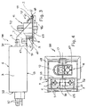
- Number 1 in Figures 1 and 2 indicates an integrated terminal board-filter assembly for fitment to the inner side of a metal casing 2 of a known electric household appliance (not shown for the sake of simplicity).
- Assembly 1 which, in Figure 1, is shown from the side facing inwards of the appliance, comprises a substantially parallelepiped main body 3 made of electrically insulating material (e.g. plastic or ceramic) and defining an inner cavity 4 housing the preassembled, prewired components 5 of a known electronic radiofrequency filter 6 not described in detail for the sake of simplicity.
- Assembly 1 also comprises a bracket 9 defined by a flat rectangular plate projecting laterally from one end 10 of main body 3; and a number of electric contacts 7, at least one of which is a ground contact 7t.
- bracket 9 is also made of electrically insulating material, and is formed integrally in one piece with main body 3; and contacts 7 are located at bracket 9, so as to be integral with bracket 9 and, at the same time, connected electrically and mechanically to components 5 of filter 6.
- assembly 1 also comprises a cable clamping device 11 formed integrally in one piece with the free end 12 of bracket 9 opposite main body 3; and, at clamping device 11 and main body 3, snap-on fastening means for connecting assembly 1 to casing 2 are provided on a mating surface for connecting assembly 1 to casing 2 and defined by a face 13 of main body 3 and by a face 19 of bracket 9.
- face 13 of main body 3 and face 19 of bracket 9 are flush with each other to form a single continuous flat mating surface facing casing 2; and said snap-on fastening means are defined by two L-shaped tabs 15 (only one shown in Figure 2) formed in one piece with body 3, projecting from face 13, and insertable bayonet-fashion inside respective openings 16 formed through casing 2, and by a flexible tooth 17 formed in one piece with bracket 9, projecting from face 19, and which clicks beneath the edge of a through opening 18 formed through casing 2 at the portion for the passage of a known cable 20 for supplying the appliance.
- Clamping device 11 may be of any known type fittable through opening 18, and preferably comprises a sleeve element 21 formed in one piece through and perpendicularly to bracket 9, and projecting partly from face 19 and partly from a flat opposite face 22 of bracket 9 parallel to face 19.
- Sleeve 21 is formed integrally in one piece with tooth 17 - which is housed partially inside a seat 23 formed through end 12 of bracket 9 - and comprises a through inner seat 24 for cable 20, and, to the side, a nut screw 25.
- Clamping device 11 also comprises a wedge-shaped cable clamping element 26 insertable gradually inside seat 24, alongside cable 20 ( Figure 1), by a screw (not shown) screwed inside nut screw 25 through clamping element 26.
- Elements 3, 9, 11 and respective components are all formed integrally in one piece, e.g. injection molded from synthetic plastic resin. More specifically clamping element 26 is formed in one piece with bracket 9, to which it is connected laterally by a known flexible tongue 28 (shown only partly in Figure 1).
- Ground contact 7t comprises a flat T-shaped tab 31 coplanar with bracket 9 and substantially flush with the surface defined by faces 13 and 19, by being housed inside a through opening 33 formed in bracket 9 and flush with wall 30 of body 3.
- Tab 31 projects from body 3 through wall 30 and into opening 33 so as to directly contact casing 2 when, in use, tabs 15 and teeth 17 are inserted inside respective openings 16 and 18.
- Tab 31 comprises two opposite threaded holes 35 for fitment to casing 2, for receiving respective known grounding screws (not shown), and which are formed through the ends of the wings of the T formed by tab 31.
- tab 31 On the front edge 36 common to both said wings, tab 31 comprises a further two projecting contacts 7, which are normally male faston types formed in one piece with tab 31; and a second number of contacts 37 project from body 3 through a lateral wall 38 of body 3 opposite wall 30 from which bracket 9 extends.
- body 3 is open laterally. More specifically, the upper face opposite bottom faces 13 and 19 is absent to enable access from the outside to the whole of cavity 4, and so enable components 5 to be assembled easily inside cavity 4, e.g. to conducting plates 40 co-molded inside cavity 4 and already connected as desired to contacts 7 and/or 37, e.g. by blanking the contacts and conducting plates from the same metal sheet.
- cavity 4 is filled with a solid insulating resin 50, e.g. a synthetic plastic resin or insulating wax, in which components 5 are embedded, and which is poured into cavity 4, after assembling components 5, and then allowed to set.
- a solid insulating resin 50 e.g. a synthetic plastic resin or insulating wax
- bracket 9 projects from the full width of body 3, parallel to and on the opposite side to the open side of body 3; and two ribs 52 for protecting contacts 7 are provided at opening 33, on opposite longitudinal sides of bracket 9, project from body 3 in one piece with body 3 and bracket 9, and taper (slope downwards) towards the free end 12 of bracket 9.
- Bracket 9 is in the form of a right-angle Z-shaped stirrup comprising a first flat portion 61 projecting from body 3 and flush with face 13 opposite cavity 4; a second portion 62 perpendicular to portion 61; and a third portion 63 parallel to portion 61 and projecting from portion 62, on the opposite side to portion 61.
- bracket 9 comprises, at portion 61, a through opening 33 in which a U-shaped conducting strip 65 projects from body 3; along at least one edge, strip 65 comprises at least one projecting faston contact 7 formed in one piece with strip 65; and a T-shaped end of strip 65 defines ground contact 7t, which, in this case, is substantially flush with portion 63 and located beneath opening 33.
- bracket 9 comprises a peripheral flange 68, which rests against the outside of casing 2 and covers a through opening or seat 18a formed through casing 2.
- the width of body 3 is smaller than that defined by flange 68 about portion 63 of bracket 9 (width in horizontal section of portion 63) so that body 3, complete with the wiring for connecting contacts 7 and the filter to the mains, is insertable from the outside through opening 18a into casing 2, opening 18a is closed by portion 63 and flange 68 of bracket 9 by rotating assembly 100 to align body 3 with casing 2, at a given distance from the inner side of casing 2, and bracket 9 is locked against casing 2 by tooth 17 and the other known snap-on fastening means (not shown), which, in the case, are provided only on portion 63.
Landscapes
- Engineering & Computer Science (AREA)
- Microelectronics & Electronic Packaging (AREA)
- Connections Arranged To Contact A Plurality Of Conductors (AREA)
- Details Of Connecting Devices For Male And Female Coupling (AREA)
- Piezo-Electric Or Mechanical Vibrators, Or Delay Or Filter Circuits (AREA)
- Control Of Motors That Do Not Use Commutators (AREA)
Applications Claiming Priority (2)
| Application Number | Priority Date | Filing Date | Title |
|---|---|---|---|
| IT96TO000347A IT1285072B1 (it) | 1996-04-30 | 1996-04-30 | Gruppo morsetteria-filtro integrato, in particolare per elettrodomestici. |
| ITTO960347 | 1996-04-30 |
Publications (2)
| Publication Number | Publication Date |
|---|---|
| EP0805617A1 EP0805617A1 (en) | 1997-11-05 |
| EP0805617B1 true EP0805617B1 (en) | 2000-04-12 |
Family
ID=11414593
Family Applications (1)
| Application Number | Title | Priority Date | Filing Date |
|---|---|---|---|
| EP97107101A Expired - Lifetime EP0805617B1 (en) | 1996-04-30 | 1997-04-29 | Integrated terminal board-filter assembly, particularly for electric household appliances |
Country Status (4)
| Country | Link |
|---|---|
| EP (1) | EP0805617B1 (it) |
| DE (1) | DE69701652T2 (it) |
| ES (1) | ES2144290T3 (it) |
| IT (1) | IT1285072B1 (it) |
Families Citing this family (7)
| Publication number | Priority date | Publication date | Assignee | Title |
|---|---|---|---|---|
| ITBL20020008A1 (it) * | 2002-04-15 | 2003-10-15 | D E M S R L | Cavo di alimentazione e filtro incorporati, particolarmente per apparecchi elettrodomestici |
| DE20303488U1 (de) | 2003-03-05 | 2003-06-26 | STOCKO Contact GmbH & Co. KG, 42327 Wuppertal | Netzanschlußdose für elektrisch betreibbare Geräte |
| DE102006037159B4 (de) * | 2006-08-02 | 2012-03-29 | Oechsler Ag | Komponententräger und Verfahren zum Herstellen einer elektrischen Baugruppe durch Verdrahten ihrer Komponenten |
| DE102008055017B4 (de) | 2008-12-19 | 2016-08-18 | BSH Hausgeräte GmbH | Geschirrspülmaschine |
| ITTV20090035A1 (it) * | 2009-03-09 | 2010-09-10 | Procond Elettronica S R L | Dispositivo integrato multifunzione, particolarmente per apparecchiature elettriche. |
| WO2018141397A1 (en) * | 2017-02-03 | 2018-08-09 | Arcelik Anonim Sirketi | Plug and play household appliance with improved electromagnetic compatibility and manufacturability |
| WO2020224854A1 (en) * | 2019-05-08 | 2020-11-12 | Arcelik Anonim Sirketi | An interference filter group and an electrical household appliance comprising the same |
Family Cites Families (2)
| Publication number | Priority date | Publication date | Assignee | Title |
|---|---|---|---|---|
| IT8653395V0 (it) * | 1986-05-13 | 1986-05-13 | Itw Fastex Italia Spa | Morsettiera di tipo perfezionato particolarmente per elettrodomesti ci |
| IT229057Y1 (it) * | 1992-11-27 | 1998-06-24 | Procond Elettronica Spa | Filtro elettrico autoportante |
-
1996
- 1996-04-30 IT IT96TO000347A patent/IT1285072B1/it active IP Right Grant
-
1997
- 1997-04-29 DE DE69701652T patent/DE69701652T2/de not_active Expired - Fee Related
- 1997-04-29 ES ES97107101T patent/ES2144290T3/es not_active Expired - Lifetime
- 1997-04-29 EP EP97107101A patent/EP0805617B1/en not_active Expired - Lifetime
Also Published As
| Publication number | Publication date |
|---|---|
| EP0805617A1 (en) | 1997-11-05 |
| DE69701652D1 (de) | 2000-05-18 |
| ITTO960347A1 (it) | 1997-10-30 |
| DE69701652T2 (de) | 2000-08-31 |
| ES2144290T3 (es) | 2000-06-01 |
| IT1285072B1 (it) | 1998-06-03 |
| ITTO960347A0 (it) | 1996-04-30 |
Similar Documents
| Publication | Publication Date | Title |
|---|---|---|
| US4729740A (en) | Fluorescent ballast having integral connector | |
| US9997860B1 (en) | Coverplate and method for electrical outlet | |
| US5040097A (en) | Central electric unit for a motor vehicle | |
| US4040699A (en) | Female connector and escutcheon plate combined therewith for telephone equipment | |
| CA1238081A (en) | Ac power cord | |
| US6655975B1 (en) | Sealed housing assembly | |
| KR960002195Y1 (ko) | 노이즈 필터 | |
| EP0805617B1 (en) | Integrated terminal board-filter assembly, particularly for electric household appliances | |
| US7038561B2 (en) | Do-it-yourself GFI outlet kit | |
| US5752856A (en) | Sealed fuse connector | |
| US5049703A (en) | Mains connection box | |
| US20200227902A1 (en) | Direct coverplate | |
| US6268561B1 (en) | Supply terminal board integrating a noise filter and cable clamp, in particular for electric household appliances | |
| JP4049821B2 (ja) | 電気器具 | |
| EP0029328A1 (en) | Electric motor construction | |
| US5864279A (en) | Temperature-dependent switch with a retaining bracket | |
| RU2422729C2 (ru) | Электронное устройство газового запальника и интегрированный коробоподобный выводной щиток, характеризующийся кабельным зажимом, в частности, для электрических бытовых приборов | |
| US6795283B2 (en) | Electricals package integrating run capacitor, motor protector and motor starter | |
| CN210779193U (zh) | 插头装置 | |
| EP0331084B1 (en) | Through type electrical connector enabling fluidtight passage of electric signals through a partition, in particular, a vehicle gearbox panel. | |
| GB2190547A (en) | A terminal board, particularly for household appliances | |
| JP3670120B2 (ja) | スイッチ装置 | |
| EP1075056B1 (en) | Integrated terminal board-filter safety assembly, in particular for electrical household appliances | |
| GB2288082A (en) | Terminal board | |
| EP1111316A1 (en) | Terminal block assembly for connecting motor-actuated compressors, particularly for refrigerators |
Legal Events
| Date | Code | Title | Description |
|---|---|---|---|
| PUAI | Public reference made under article 153(3) epc to a published international application that has entered the european phase |
Free format text: ORIGINAL CODE: 0009012 |
|
| AK | Designated contracting states |
Kind code of ref document: A1 Designated state(s): DE ES FR GB |
|
| 17P | Request for examination filed |
Effective date: 19980429 |
|
| GRAG | Despatch of communication of intention to grant |
Free format text: ORIGINAL CODE: EPIDOS AGRA |
|
| 17Q | First examination report despatched |
Effective date: 19990226 |
|
| GRAG | Despatch of communication of intention to grant |
Free format text: ORIGINAL CODE: EPIDOS AGRA |
|
| GRAH | Despatch of communication of intention to grant a patent |
Free format text: ORIGINAL CODE: EPIDOS IGRA |
|
| RAP1 | Party data changed (applicant data changed or rights of an application transferred) |
Owner name: MILLER EUROPE S.P.A. Owner name: I.T.W. FASTEX ITALIA S.P.A. |
|
| GRAH | Despatch of communication of intention to grant a patent |
Free format text: ORIGINAL CODE: EPIDOS IGRA |
|
| GRAA | (expected) grant |
Free format text: ORIGINAL CODE: 0009210 |
|
| AK | Designated contracting states |
Kind code of ref document: B1 Designated state(s): DE ES FR GB |
|
| REF | Corresponds to: |
Ref document number: 69701652 Country of ref document: DE Date of ref document: 20000518 |
|
| REG | Reference to a national code |
Ref country code: ES Ref legal event code: FG2A Ref document number: 2144290 Country of ref document: ES Kind code of ref document: T3 |
|
| ET | Fr: translation filed | ||
| PGFP | Annual fee paid to national office [announced via postgrant information from national office to epo] |
Ref country code: FR Payment date: 20001030 Year of fee payment: 5 |
|
| PLBE | No opposition filed within time limit |
Free format text: ORIGINAL CODE: 0009261 |
|
| STAA | Information on the status of an ep patent application or granted ep patent |
Free format text: STATUS: NO OPPOSITION FILED WITHIN TIME LIMIT |
|
| 26N | No opposition filed | ||
| PGFP | Annual fee paid to national office [announced via postgrant information from national office to epo] |
Ref country code: ES Payment date: 20010406 Year of fee payment: 5 |
|
| REG | Reference to a national code |
Ref country code: GB Ref legal event code: IF02 |
|
| PG25 | Lapsed in a contracting state [announced via postgrant information from national office to epo] |
Ref country code: ES Free format text: LAPSE BECAUSE OF NON-PAYMENT OF DUE FEES Effective date: 20020430 |
|
| PG25 | Lapsed in a contracting state [announced via postgrant information from national office to epo] |
Ref country code: FR Free format text: LAPSE BECAUSE OF NON-PAYMENT OF DUE FEES Effective date: 20021231 |
|
| REG | Reference to a national code |
Ref country code: FR Ref legal event code: ST |
|
| REG | Reference to a national code |
Ref country code: ES Ref legal event code: FD2A Effective date: 20030514 |
|
| PGFP | Annual fee paid to national office [announced via postgrant information from national office to epo] |
Ref country code: DE Payment date: 20040601 Year of fee payment: 8 |
|
| PG25 | Lapsed in a contracting state [announced via postgrant information from national office to epo] |
Ref country code: DE Free format text: LAPSE BECAUSE OF NON-PAYMENT OF DUE FEES Effective date: 20051101 |
|
| PGFP | Annual fee paid to national office [announced via postgrant information from national office to epo] |
Ref country code: GB Payment date: 20140428 Year of fee payment: 18 |
|
| GBPC | Gb: european patent ceased through non-payment of renewal fee |
Effective date: 20150429 |
|
| PG25 | Lapsed in a contracting state [announced via postgrant information from national office to epo] |
Ref country code: GB Free format text: LAPSE BECAUSE OF NON-PAYMENT OF DUE FEES Effective date: 20150429 |