EP0805948B1 - Dispositif et procede de balayage - Google Patents
Dispositif et procede de balayage Download PDFInfo
- Publication number
- EP0805948B1 EP0805948B1 EP95929175A EP95929175A EP0805948B1 EP 0805948 B1 EP0805948 B1 EP 0805948B1 EP 95929175 A EP95929175 A EP 95929175A EP 95929175 A EP95929175 A EP 95929175A EP 0805948 B1 EP0805948 B1 EP 0805948B1
- Authority
- EP
- European Patent Office
- Prior art keywords
- scanning device
- scanning
- optical
- output data
- relative
- Prior art date
- Legal status (The legal status is an assumption and is not a legal conclusion. Google has not performed a legal analysis and makes no representation as to the accuracy of the status listed.)
- Expired - Lifetime
Links
Images



Classifications
-
- G—PHYSICS
- G01—MEASURING; TESTING
- G01B—MEASURING LENGTH, THICKNESS OR SIMILAR LINEAR DIMENSIONS; MEASURING ANGLES; MEASURING AREAS; MEASURING IRREGULARITIES OF SURFACES OR CONTOURS
- G01B11/00—Measuring arrangements characterised by the use of optical techniques
- G01B11/24—Measuring arrangements characterised by the use of optical techniques for measuring contours or curvatures
-
- G—PHYSICS
- G01—MEASURING; TESTING
- G01B—MEASURING LENGTH, THICKNESS OR SIMILAR LINEAR DIMENSIONS; MEASURING ANGLES; MEASURING AREAS; MEASURING IRREGULARITIES OF SURFACES OR CONTOURS
- G01B11/00—Measuring arrangements characterised by the use of optical techniques
- G01B11/24—Measuring arrangements characterised by the use of optical techniques for measuring contours or curvatures
- G01B11/25—Measuring arrangements characterised by the use of optical techniques for measuring contours or curvatures by projecting a pattern, e.g. one or more lines, moiré fringes on the object
-
- G—PHYSICS
- G01—MEASURING; TESTING
- G01B—MEASURING LENGTH, THICKNESS OR SIMILAR LINEAR DIMENSIONS; MEASURING ANGLES; MEASURING AREAS; MEASURING IRREGULARITIES OF SURFACES OR CONTOURS
- G01B11/00—Measuring arrangements characterised by the use of optical techniques
- G01B11/08—Measuring arrangements characterised by the use of optical techniques for measuring diameters
-
- G—PHYSICS
- G01—MEASURING; TESTING
- G01C—MEASURING DISTANCES, LEVELS OR BEARINGS; SURVEYING; NAVIGATION; GYROSCOPIC INSTRUMENTS; PHOTOGRAMMETRY OR VIDEOGRAMMETRY
- G01C3/00—Measuring distances in line of sight; Optical rangefinders
- G01C3/02—Details
- G01C3/06—Use of electric means to obtain final indication
- G01C3/08—Use of electric radiation detectors
-
- G—PHYSICS
- G01—MEASURING; TESTING
- G01S—RADIO DIRECTION-FINDING; RADIO NAVIGATION; DETERMINING DISTANCE OR VELOCITY BY USE OF RADIO WAVES; LOCATING OR PRESENCE-DETECTING BY USE OF THE REFLECTION OR RERADIATION OF RADIO WAVES; ANALOGOUS ARRANGEMENTS USING OTHER WAVES
- G01S17/00—Systems using the reflection or reradiation of electromagnetic waves other than radio waves, e.g. lidar systems
- G01S17/02—Systems using the reflection of electromagnetic waves other than radio waves
- G01S17/06—Systems determining position data of a target
- G01S17/42—Simultaneous measurement of distance and other co-ordinates
-
- G—PHYSICS
- G06—COMPUTING OR CALCULATING; COUNTING
- G06T—IMAGE DATA PROCESSING OR GENERATION, IN GENERAL
- G06T7/00—Image analysis
- G06T7/50—Depth or shape recovery
- G06T7/521—Depth or shape recovery from laser ranging, e.g. using interferometry; from the projection of structured light
-
- G—PHYSICS
- G01—MEASURING; TESTING
- G01S—RADIO DIRECTION-FINDING; RADIO NAVIGATION; DETERMINING DISTANCE OR VELOCITY BY USE OF RADIO WAVES; LOCATING OR PRESENCE-DETECTING BY USE OF THE REFLECTION OR RERADIATION OF RADIO WAVES; ANALOGOUS ARRANGEMENTS USING OTHER WAVES
- G01S7/00—Details of systems according to groups G01S13/00, G01S15/00, G01S17/00
- G01S7/48—Details of systems according to groups G01S13/00, G01S15/00, G01S17/00 of systems according to group G01S17/00
- G01S7/481—Constructional features, e.g. arrangements of optical elements
- G01S7/4817—Constructional features, e.g. arrangements of optical elements relating to scanning
Definitions
- the present invention relates to a scanning arrangement and method for determining the shape, size or other three-dimensional surface characteristics of an object, such as colour for example.
- the Schulz system requires an externally generated coordinate system defined by an array of photodetectors which detects an array of pilot lights on the scanner. Hence the scanner can only be used within this coordinate system and furthermore the array of pilot lights must be kept in view by the array of photodetectors, which further restricts the mobility of the scanner. This is a serious disadvantge because it is normally necessary to scan the object of interest from all sides in order to build up a complete picture of its surface.
- GB-A-2 045 938 is used for measuring dimensions of an object. It uses inertial navigation techniques to measure dimensions of an object and comprises a probe body having a barrel and, optionally, a pistol-like grip. A probe tip extends from the body, its free end being aligned with the longitudinal axis of the body. Inside the body are six accelerometers, which are respectively aligned parallel to three orthogonal axes x, y, z, the x-axis being coincident with the body's longitudinal axis.
- data from the accelerometers representing the accelerations of the free end of the probe tip in six degrees of freedom is integrated twice by an electronic calculating assembly to provide an output indicative of the instantaneous position of the probe tip free end relative to said datum, which may be visually displayed by a device.
- An object of the present invention provides a scanning arrangement and method in which the scanner can be moved freely without reference to the position of its mounting.
- the invention provides a scanning arrangement for determining the shape of an object, the arrangment comprising:
- the correcting means effectively consists of the combining means, which comprises further processing means for determining the translations and/or rotations required to combine the data from successive scans.
- the scanning device carries inertial sensing means for sensing its linear acceleration and rotation sensing means for sensing its rate of rotation.
- the invention provides a scanning arrangement for determining the shape of an object, the arrangment comprising:
- the invention also provides a method according to the first aspect of determining the shape of an object by means of an optical scanning device, the method comprising:
- the invention also provides a method according to the second aspect of determining the shape or other three-dimensional surface characteristics of an object by means of an optical scanning device which is freely movable with respect to the object, the method comprising:
- the generally T-shaped scanning device 10 shown schematically in Figure 1 is hand held and comprises a projector which generates a vertical fan-shaped beam of light 3 onto an object 1 of unknown shape and a lens 33 which collects diffusely reflected light 4 from the illuminated region of the object and images the projection 13 of this beam on the object's surface onto a two-dimensional photodetector 34.
- the beam 3 is generated by a laser 29 (which is preferably a semiconductor laser with beam-shaping optics but may be a He-Ne laser for example) and a cylindrical lens 30 and the photodetector 34 may consist of a two-dimensional CCD array with several hundred photosensitive elements along each dimension for example.
- the scanning device can be generally C-shaped, having the beam generator in one limb, the photodetector in the other and a grip between the two limbs, and can be used with the grip approximately vertical and the fan-shaped beam approximately horizontal.
- the photodetector 34 is inclined in the horizontal (z-x) plane at an angle ⁇ to the xy plane, whose normal is parallel to the optical axis of the lens 33, ⁇ being such that the Scheimpflug condition is satisfied.
- the image of the photodetector 34 is projected by lens 33 into the plane of fan-shaped beam 3 and the image 13' formed on the photodetector 34 corresponds to the profile of the object surface as viewed at a right angle to the plane of beam 3.
- a ridge 11 is shown on the front of the object and this feature is clearly visible in the image 13 of the profile.
- the scanning device 10 is used to sweep the stripe 13 over the entire surface of object 1.
- the changes in angular orientation of the scanning device are detected by a vibratory gyroscope 51 which generates output signals ⁇ x , ⁇ y , ⁇ z indicative of the rate of rotation of scanning device 10 about axes x, y and z respectively.
- Miniature vibratory gyroscopes are commercially available at low cost and rely on Coriolis forces set up in a vibrating shell or other structure.
- the acceleration of the scanning device along the x, y and z axes is detected by an accelerometer 50 which generates respective acceleration signals a x , a y and a z respectively.
- the sensitive axes of the gyroscope 51 are close to the centre of photodetector 34 in order to simplify subsequent computation but this is not essential.
- the scanning device also includes a trigger switch T which is operable by the user to start and stop the acquisition of data from the photodetector.
- This trigger switch T outputs control signals c.
- the circuitry for processing the output signals from the photodetector 34, the gyroscope 51 and the accelerometer 50 is shown in Figure 2. These output signals may be conveyed to the circuitry by a flexible cable or wireless link for example or may for example be digitised and stored in local memory such as a high capacity miniature hard disc (not shown) in the scanning device, enabling the scanning device to be used remotely from its processing circuitry and enabling the processing to be carried out after scanning has been completed. At least some of the circuitry of Figure 2 may be located in the scanning device.
- the generation and/or acquisition of data from the photodetector 34 is gated by signals from the gyroscope 51 and/or accelerometer 50 which prevent the determination of position and/or attitude of the scanner under conditions in which the angular rotation or acceleration are too great or too small (e.g. as a result of noise or drift) to enable accurate calculations to be made.
- the accelerometer is shown as three blocks 50a to 50c which output signals indicative of the acceleration along the x, y and z axes respectively and the gyroscope is similarly represented as blocks 51a to 51c which output signals indicative of the rate of rotation about axes x, y and z respectively.
- the acceleration signals are amplified by conventional low noise and drift preamplifier circuits and fed via sample and hold circuitry 45 to an 14 bit analoeue-to-digital converter 20.
- the rotation signals are amplified by conventional low noise and drift preamplifier circuits and fed via sample and hold circuitry 56 to a 14 bit analogue-to-digital converter 55.
- the sample-and -hold circuitry 45, 55 samples at a rate of 5,000 per second.
- the digitised signals from analogue-to-digital converters 20 and 55 are fed to signal conditioning circuits 21 and 52 respectively which include digital filters for filtering out noise, correct for nonlinearity in the accelerometer or gyroscope outputs (e.g. by employing look-up tables) and correct for drift due to temperature variations.
- the resulting data is fed to a digital signal processor 23 where corrections are made for the offsets (if any) of the sensitive axes of the gyroscope 51 from the photodetector 34 and for the distance between the accelerometer 50 and the gyroscope 51.
- Such corrections are necessary because, for example a sudden rotation centred on accelerometer 50 would cause a significant acceleration of photodetector 34 but would not be detected as such by the accelerometer.
- the resulting rate of change of the rate of rotation detected by gyroscope 51 could be used, in conjunction with the known separation between the accelerometer and gyroscope and the output of the accelerometer, to calculate the acceleration of the photodetector, as will be apparent to persons skilled in the art.
- the rate of rotation and acceleration of the photodetector could be calculated from the outputs of two spaced apart gyroscopes (each sensitive about all three axes) or two spaced apart accelerometers (each sensitive along all three axes) provided that their positions relative to the photodetector were known.
- the processor 23 double integrates successive values of the corrected photodetector acceleration (along the x, y and z axes) by means of a double integration algorithm to determine the instantaneous position of the photodetector (relative to an arbitrary starting position) throughout the scan. Since the sample and hold circuits 45 and 56 are clocked at a rapid rate (e.g. 5 kHz) by clocking circuitry 57, this position sensing takes place essentially in real time.
- a rapid rate e.g. 5 kHz
- the processor 23 integrates successive values of the corrected photodetector rate of rotation (about the x, y and z axes) by means of an integration algorithm to determine the instantaneous orientation of the photodetector throughout the scan, again essentially in real time.
- the above integrations are performed on groups of 100 samples to update position and attitude 50 times per second, which matches the sampling rate of photodetector 34.
- correction circuitry 28 corrects for any distortion in the optics of the scanning device 10 (particularly distortion by the lens 33), derives the true profile of projected stripe 13 (as viewed at right angles to the plane of beam 3) from the image 13' by applying appropriate corrections (e.g.
- the scan data processor 25 receives signals representative of the true profile of the object 1 (as viewed at right angles to the plane of beam 3) as well as signals representative of the attitude and position of the photodetector 34 (which bears a fixed relationship to the position and attitude of the region of beam 3 which intersects the surface of the object 1), all in real time.
- signals representative of the true profile of the object 1 as viewed at right angles to the plane of beam 3
- signals representative of the attitude and position of the photodetector 34 which bears a fixed relationship to the position and attitude of the region of beam 3 which intersects the surface of the object 1.
- data is not acquired throughout the scanning period but only intermittently, either under the control of an operator-controlled switch T on the scanning device 10 or under the control of signals from the accelerometer and/or the gyroscope or for predetermined periods for example.
- Such signals can for example either be used to drive an indicator such as an LED to indicate to the operator that the acceleration and/or rate of rotation are within an acceptable range for data acquisition or can be used as gating signals to block the acquisition of data e.g. by disabling the clocking signals from circuitry 57 to sample and hold circuit 26.
- the processor 25 only applies the rotations and translations corresponding to a group of successive profiles to generate a surface description of a small region of the scanned surface and stops generating this surface description (which will be a cloud of points in a common coordinate system) under the control of the operator and/or under the control of the above gating signals.
- a further surface description of another surface portion will then be generated in a similar manner e.g. in response to further operation of the switch or release of the gating signals. In this manner, successive scan files each comprising a cloud of points representative of a different but overlapping surface portion are generated.
- the position and attitude of the scanning device 10 is monitored throughout the scanning and accordingly the position and attitude of the photodetector 34 at the beginning of the generation of each scan file is known (albeit possibly with some accumulated errors) and is associated with the three-dimensional coordinate data of that scan file.
- each scan file consists of a three-dimensional cloud of points describing the surface coordinates of a region of the scanned surface, in association with data representative of the position and orientation of the photodetector 34 during the acquisition of each profile of that set.
- Successive scan files are output from processor 25 to a computer 47, which is provided with a display 131 and a keyboard 130.
- Figure 3 shows a projector and detector which project a two-dimensional optical pattern onto the surface 35 of the object and detect an array of surface profiles of the object from this pattern. Accordingly this arrangement enables the acquisition of a set of three-dimensional coordinate data defining a surface portion of the scanned object without requiring any position or orientation signals, and can be substituted for the optical arrangement shown in Figure 1.
- a semiconductor laser 29' transmits a laser beam to an optical arrangement 300 which may either include a cylindrical lens arranged to form a fan-shaped beam oriented perpendicular to the plane of the drawing or a scanner such as an oscillating mirror arrangement arranged to oscillate the beam perpendicular to the plane of the drawing to form a corresponding fan-shaped envelope.
- the resulting fan-shaped beam or envelope is then directed by a fixed mirror onto a 24 facet polygonal mirror 40 rotating at 20,000 r.p.m. which scans a beam or envelope 3' in the plane of the drawing as shown.
- the profile (represented as an arrow a or b) defined by the intersection of this beam or envelope with the surface of the object is imaged by a lens 33 onto an inclined photodetector 34' and forms a corresponding image a' or b'.
- detector 34' satisfies the Scheimpflug condition in order to maximise the depth of field.
- the profile a or b of the surface can be determined from the corresponding image a' or b'.
- the instantaneous orientation of the beam or envelope 3' in the plane of the drawing must be known and accordingly the angular position of the polygonal mirror 40 is sensed by a sensor 41 which sends an angular position signal to a processor 42.
- Processor 42 samples the output of photodetector 34' in synchronism with the position signal from 41 and each resulting profile calculated by processor 42 is aligned relative to a common coordinate system according to the angular position signal.
- the output of processor 41 is a cloud of points in a three-dimensional coordinate system which define the surface portion scanned by beam 3'.
- arrangement 300 includes a scanner which oscillates the laser beam rapidly perpendicular to the plane of the drawing (e.g.
- the term 'effectively instantaneous' acquisition of data is used to describe an acquisition of many surface points in a two dimensional matrix or raster projected onto the surface of the object in a period which is so short that the maximum movement expected of the scanning device 10 in this time will be less than the required accuracy of the surface profile data.
- each acquisition will contain at least several hundred points.
- acousto-optic deflector and electro-optic deflector systems which may optionally be combined with a resonant line scanner. All of these systems are capable of projecting a spot onto the surface at a variable angle to the scanning device in two dimensions, and can control the angle of projection at high speed.
- acousto-optic deflectors can currently be obtained to alter the refractive index of a crystal to divert the beam in any one of up to 1000 linearly spaced unique angles.
- Certain acousto-optic devices may be coupled to provide XY random access deflection.
- the rotating polygonal mirror system described above requires a medium-speed rotating polygonal mirror 40 to provide the line scan in each line of the raster, and a low-speed scanner such as a further rotating poygonal mirror in optical arrangement 300 to provide the vertical raster movement repositioning the start of each line.
- a low-speed scanner such as a further rotating poygonal mirror in optical arrangement 300 to provide the vertical raster movement repositioning the start of each line.
- polygonal mirror 40 provides a scan rate of 8,000 lines/sec if a 24 facet polygon is used (15 degree angle of scan), and scans 32 lines in 4ms.
- the preferred photodetector 34' is a lateral effect two dimensional linear silicon photodetector which generates an output indicating the offset of the centroid of the incident light relative to the centre of the photodetector in continuous analogue form.
- Such photodetectors are capable of resolving optical changes at several MHz.
- the processor 42 in the embodiment of Figure 3 preferably includes high speed flash analogue-to-digital converters which digitise the X and Y centroid signals from the photodetector which correspond to the surface profile at specific angle of projection of beam 3' at that point at the time of measurement.
- the digitised points are then converted to points in a three-dimensional coordinate system which is common to the entire scan performed by polygonal mirror 40 with the aid of signals from sensor 41, which may be a Hall effect sensor for example. These signals indicate the instantaneous orientation of beam 3'. If an acousto-optic device is used for scanning, the required information on the beam orientation can be derived from the drive signals to the device.
- each successive scan file can contain a very high proportion (e.g. 50% or more) of the data in the preceding scan, thus making overlapping almost complete. This enables the surface portions corresponding to successive scan files to be combined relatively easily to obtain a complete surface description of the object 1.
- Figure 3 is shown with an accelerometer 50 and a gyroscope 51 which are similar to the acclerometer and gyroscope of Figure 1, it is not essential for the output of processor 42 to be combined with data derived from such an accelerometer and a gyroscope in order to give a succession of scan files including the required position and attitude data as generated by circuitry 25 in Figure 1. Instead the scanned surface portions can be combined by a computer without the assistance of such data, as will become apparent from the subsequent description.
- the signals from the accelerometer and gyroscope can be used a) to derive the change in position and attitude of the scanning device between successive scan files so that successive pairs (or larger groups) of scan files can be combined to form composite scan files which require less processing to be fitted together to form the complete surface description and b) to provide position and attitude signals to the subsequent processing circuitry which indicate to that circuitry where regions of overlap between successive scan files may be found, thereby simpifying processing.
- the use of such signals will be described subsequently with reference to Figure 5.
- Data scan file of raw 3D coordinate data
- a scan commences.
- the trigger switch T is released, or the speed in any direction falls below a second (lower) threshold (for hysteresis)
- the scan is terminated.
- profile acquisitions are made at regular time intervals, and thus the number of profiles is directly proportional to the duration of the scan.
- Each profile acquisition will contain a number of distance samples along the length of the profile.
- a number of extra data items may be included in each scan file in order to assist various subsequent processes in performing error correction such as a scan file time stamp to indicate the time of the start of the scan, scanning device position and attitude, and surface colour in another embodiment.
- the scan file consists of essentially a set of randomly placed and unassociated points on which any further processing is extremely difficult as the points are unordered and in an unsuitable format for later post processing stages.
- This process fits a mathematical model to the surface described by the randomly ordered points in the scan file which is in a form suitable for later post processing operations. It should be noted that this mathematical model is not necessarily an expression for the surface in terms of x,y and z coordinates but is merely an ordered form of the raw data which enables features of interest such as discontinuities to be extracted in subsequent processes. This has two effects: ordering the data to a known format, and production of a complete surface model of the scanned area regardless of varying data density.
- Voronoi diagram In the Delaunay Triangulation of Voronoi diagram (Toussaint 1979), a Voronoi diagram is built up by defining a plane associated with each detected surface point such that each point within that plane is nearer to that detected surface point than to any of the other detected surface points. Thus a polyhedron is built up whose polygonal faces are centred on respective detected surface points, the edges of the polygonal faces being midway between neighbouring detected surface points. The resulting partial polyhedron is then simplified by defining a triangular face between three detected surface points and measuring the perpendicular distance between it and the intermediate detected surface points lying above it.
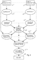
- the data resulting from process 62 will be a surface model in a form suitable for the extraction of points of interest.
- This surface model can be in the form of a set of splines, a binar, tree, or a set of connected triangles or other polygons depending on the precise method used in process 62.
- the methods for detecting these features include i) plane slicing and ii) surface curvature analysis.
- surfaces are essentially featureless, small and easily removable markers of known shape and size may be placed on the object to be scanned in order to generate artificial "points of interest". These may be removed from the scan file at the end of the processing by a process of subtracting the appropriate 3-D model.
- surface curvature can be used to find discontinuities in a surface by detecting points with diverging splines. This method can also be used to detect surface features that will not be detected by other means, in that a smooth parabolic surface can be completely described mathematically, and used as a point of interest (its gradient passes through zero) for scan registration rather than surface point features as in the other methods.
- the data flow from process 63 comprises "points of interest" associated with each scan file and can be represented by a list (e.g. peak, saddle, saddle, trough) linked to a further list of spatial relationships between each of the points of interest.
- Each point of interest in the first list can be described by the following set of data or some subset:
- a search is performed for similar point of interest types, resulting in a list of common point of interest types between the pair of scan files.
- the relative spatial relationships between the common points of interest in the list for each scan can be compared by first matching distances between pairs of similar types to produce a subset of the original list where the spatial relationship between pairs of points of interests is matched.
- the relative spatial relationship of other neighbouring points of interest to the matching pair from each scan is then checked for a match containing three points of interest to produce a subset of the matching triplets of points of interest. This is the minimal requirement for determining that any set of features are common between scans. The process is continued until no further matches are found. The larger the number of matched points of interest, the greater the confidence in a correct matching between overlapping surface features between scans.
- Scan file 1 Scan file 2 peak peak peak ridge ridge saddle pit minimal surface pit pit
- Scan file 1 Scan file 2 peak-peak distance peak-ridge distance peak-ridee .. a peak-pit .. a peak-ridge .. b peak-pit .. b peak-pit .. a peak-pit .. c peak-pit .. b ridge-pit .. a ridge-pit .. ridge-pit .. b ndge-pit .. c
- Each distance in scan file 1 is compared with corresponding distances (i.e. distances between corresponding groups of features, e.g. peak-ridge) in scan file 2. It may be found that peak-ridge distance a of scan file 1 matches the peak ridge distance of scan file 2, that the peak-pit distances a of the respective scan files match and that the ridge-pit distance of scan file 1 matches the ridge-pit distance a of scan file 2, for example. These matching distances are then processed to find the list of sets of three distances between the possible combinations of the three different features.
- the resulting lists in this case each comprise one set of distances between a peak, a ridge and a pit: Scan file 1 peak-ridge distance, peak-pit distance, ridge-pit distance Scan file 2 peak-ridge distance, peak-pit distance, ridge-pit distance
- rotations and translations are applied to the clouds of points of all the overlapping scan files, resulting in a single cloud of points defining the entire surface of the scanned object relative to an arbitrary coordinate system.
- these rotations and translations may be applied to surface models generated in step 62.
- the resulting data is of an identical type to the original scan file cloud of points or surface model, but translated to the common coordinate system.
- This method places no restrictions on the topology of the object to be modelled and is the single most useful method, although all three methods are available within process 66 and can be selected by the user by entering appropriate commands at the keyboard 130 of the computer 47 (Fig. 2).
- the Venn diagram is obtained by calculating the common surface segments between all possible pairs of range views. Each area of overlap of surface features between two or more range views becomes a canonical subset of the Venn diagram.
- the procedure to obtain the Venn diagram from the set of range views consists of finding the intersections between all possible pairs of range views, and once computed, it is possible to determine for each point in each view, which other views have sampled an element on the surface at that point. The contents of the canonical subsets of the Venn diagram are thus implicitly available.
- the Spatial Neighbourhood Test is used to check whether the Euclidian distance between a point in one view, and a surface patch in another view is small enough in relation to the measurement error to determine that they belong to the same 3D neighbourhood.
- the definition of the surface patch is local and is defined as the plane formed by the three nearest neighbours of the point once transformed in the parametric grid of the other view.
- these initial estimates are used as seeds to an iterative region growing process that expands the seeds until they reach the boundaries marked by contours of steep discontinuity pixels.
- a consistency criterion must also be imposed to prevent an isolated point from growing freely. This criterion can be defined as at least fifty per cent of elements in an expanded region must be SNT and SVT TRUE.
- the region growing algorithm relies on a modified 8-neighbour blob colouring algorithm. Instead of checking whether two 8-connected pixels in a given view share the same property or not, it checks to see if they are disconnected by a contour of step continuity pixels 4-connected to elements of a seed region in either of the views.
- the resulting model in a custom format, is output from process 66 to process 67.
- the complete integrated triangulation model is used as the input data to a file format converter to produce a file describing the object in a standard file format suitable for display, manipulation and storage by a large number of 3D software packages including but not limited to CAD on a wide variety of platforms.
- Common 3D file formats which can be supported by the file format conversion utility include:
- This data is output to a CAD software package 68.
- the computer 47 is surtably a graphics workstation or may be a high speed personal computer.
- an object 1' (a paper cup) is shown being scanned by a scanning device 10, which is assumed to incorporate the preferred optical arrangement and accelerometer and gyroscope of Figure 3.
- the corners of the first scan i.e. that area covered by one horizontal sweep of beam 3' due to the rotation of the polygonal mirror 40
- p,q,r the corners of the first scan
- s the corners of the next scan t,u,v,w.
- a second row of two further scans are shown on the surface of the cup and the operator holding the scanning device 10 ensures that the two rows overlap.
- the overlap between successive scans pqrs and tuvw is due to the rapid scanning rate of polygonal mirror 40 in relation to the rate at which the projected beam from the scanning device is swept across the surface of the scanned object 1'. Accordingly it is inevitable that the edge region of each scan (e.g. the region of scan pqrs shown hatched) will overlap the edge region of the next scan. For example, the edge region between corners r and of the first scan shown in Figure 5 will overlap the edge region between corners t and u of the second scan.
- COMMON FEATURE DETECTOR process 64 in Figure 4 can be guided to look in the edge region of each scan file for overlap, preferably in real time as the scan files are generated by scanning device 10. In other words, instead of waiting until all of the scan files have been generated and then looking for overlap between every possible pair of scan files, the process 64 can look for overlap between regions (particularly edge regions) of successively generated scan files.
- inertial sensing means such as accelerometer 50 and gyroscope 51 are carried by scanning device 10
- the outputs of such inertial sensing means can be processed to determine the velocity and direction of movement of the scans over the surface of the object 1' and hence to predict the precise regions of overlap of successive scan files.
- the inertial sensing means is omitted, the velocity and/or direction of movement between the first two scans can be derived from the location of the common features in their scan files and can be used to predict, to a first approximation, the region in which the next two scans will overlap, so that COMMON FEATURE DETECTOR process 64 will look only in this region for common features.
- the processing needed to identify common points in successive scan files is much reduced and should be easily achievable in real time.
- a docking station 100 is provided, to which the scanning device may be returned periodically during scanning. If each sweep is begun by taking the scanning device from the docking station, the accumulated errors from the accelerometer and gyroscope can be reduced. Furthermore a reference object 200 of known size and shape may be scanned before the object 1' is scanned and used to calibrate the system.
- a file defining the entire surface of object 1' could be built up, provided that the object is kept in view by the photodetector 34' of the scanning device 10 throughout whilst sweeping the entire surface of the object with the projected pattern from the scanning device.
- this may not always be practicable and in general it may be easier to combine successive scan files defining part of the surface of the object to form a composite scan file, to repeat this process to form further composite scan files, and then to combine the composite scan files at the end of the scanning process by means of processes 64 and 65 of Figure 4 to form a complete surface description.
- the SURFACE FIT process 62 of Figure 4 can be simplified if the coordinate data of all the points is read out from the processor 47 ( Figure 3) in serial fashion in a predetermined order (such as the order of acquisition for example) or in some other manner which preserves the information on their location within the scan.
- the nearest neighbours of each point can be identified from such information without requiring the calculation of the distances between all pairs of points, and hence a surface can be built up by joining each point to its nearest neighbours. Assuming that the angle of sweep of beam 3' in the scanning arrangement of Figure 4 is relatively small, the resulting surface will approximate to a projection on a rectangular grid.
- a similar method for reorientation and registration of data files in 6 dimensional space may be derived easily from the techniques described in Report No. STAN-CS-TR-95- 1535 Thesis: Random Networks in Configuration Space for Fast Path Planning', December 1994 by Lydia E. Kavraki, Department of Computer Science, Stanford University, Stanford, California 94305, which is also incorporated herein by reference.
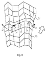
- Figure 6 shows two surfaces S1 and S2 in the form of projections on a rectangular grid which have been derived from successive scan files output from the scanning arrangement of Figure 4.
- the normals N defined by (say) the four adjacent points of one surface S2 are calculated at least for the overlapping edge portions of the surface and then a) the distance along each normal at which it cuts surface S2 is calculated and b) the three rotations and translations needed to minimise the sum of these distances of intersection (corresponding to the best overlap) is determined by the genetic or other iterative algorithm.
- Such a technique does not require the detection of discontinuities or other "points of interest".
- a further embodiment of the present invention could provide simultaneous capture of a colour and texture overlay with surface position data, by the use of a colour CCD or similar two dimensional colour photodetector device instead of, or in addition to, the present photodetector, while strobing the laser or using a broadband light source.
- a still further embodiment of the present invention may retain the inertial position and attitude measurement system as described in connection with Figures 1 and 2 but may use any other means for determining the surface coordinates relative to the scanning device.
- the position and attitude measurement system may be mounted on the object to be measured and the object can be moved around the fixed scanning device, or a further position and attitude measurement system may be provided on the object being scanned in addition to that on the scanning device, enabling both the scanned object and the scanning device to be moved freely.
- the laser 28 used as the light source may be replaced by a light-emitting diode and other wavelengths besides optical wavelengths can be used, particularly I.R. wavelengths. Accordingly the term "optical” is to be construed broadly to include any radiation or arrangement which obeys the laws of optics.
- a still further embodiment of the present invention could utilise a controllable lens system with variable magnification in order to provide increased dynamic range of depth measurement.
- a still further embodiment of the present invention could include a density, mass and volume calculator in the computer (47).
- inert fine powder for example fingerprinting dust
Landscapes
- Physics & Mathematics (AREA)
- Engineering & Computer Science (AREA)
- General Physics & Mathematics (AREA)
- Electromagnetism (AREA)
- Computer Vision & Pattern Recognition (AREA)
- Radar, Positioning & Navigation (AREA)
- Remote Sensing (AREA)
- Computer Networks & Wireless Communication (AREA)
- Optics & Photonics (AREA)
- Theoretical Computer Science (AREA)
- Length Measuring Devices By Optical Means (AREA)
- Container Filling Or Packaging Operations (AREA)
- Vehicle Body Suspensions (AREA)
- Investigating Or Analyzing Materials By The Use Of Ultrasonic Waves (AREA)
- Gyroscopes (AREA)
- Length Measuring Devices With Unspecified Measuring Means (AREA)
- Position Input By Displaying (AREA)
- Radar Systems Or Details Thereof (AREA)
- Eye Examination Apparatus (AREA)
Claims (32)
- Agencement de balayage pour déterminer la forme d'un objet (1), l'agencement comportant :a) un dispositif de balayage optique (10) destiné à saisir optiquement des coordonnées de surface de régions superficielles chevauchantes de l'objet par rapport au dispositif de balayage, le dispositif de balayage optique étant mobile librement par rapport audit objet ;b) des moyens de traitement (25, 26, 27) couplés au dispositif de balayage pour générer un ensemble de données de sortie représentant des coordonnées de surface d'une partie balayée (pqrs, tuvw) desdites régions superficielles ;c) des moyens de combinaison (47) couplés auxdits moyens de traitement pour combiner des ensembles de ces données de sortie dérivés de balayages chevauchants de ladite surface en un ensemble commun de données de sortie par des rotations et des translations appropriées, lesdits moyens de combinaison comprenant en outre des moyens de traitement (61-66) agencés pour déterminer lesdites translations et rotations appropriées en reconnaissant des caractéristiques dudit objet communes à des régions superficielles chevauchantes, et en traduisant lesdits ensembles de données de sortie en un système de coordonnées commun, etd) des moyens de correction (23, 47) destinés à corriger un mouvement dudit dispositif de balayage par rapport audit objet entre des balayages successifs, lesdits moyens de correction réagissant à des données de sortie provenant desdits autres moyens de traitement,
- Agencement selon la revendication 1, dans lequel lesdits moyens de combinaison (47) comprennent un moyen destiné à dériver des normales (N) à des régions superficielles balayées (S1) et un moyen destiné à déterminer, sous différentes rotations et translations, les distances le long de ces normales auxquelles elles coupent d'autres régions de surface (S2).
- Agencement pour déterminer la forme d'un objet (1), l'agencement comportant :a) un dispositif de balayage optique (10) destiné à saisir optiquement des coordonnées de surface de régions superficielles chevauchantes de l'objet par rapport au dispositif de balayage, le dispositif de balayage étant mobile librement par rapport audit objet ;b) des moyens de traitement (25, 26, 27) couplés au dispositif de balayage optique pour générer un ensemble de données de sortie représentant des coordonnées de surface desdites régions superficielles ;c) des moyens de détection inertielle (50, 51) destinés à détecter un mouvement dudit dispositif de balayage optique par rapport à l'objet et à générer des signaux de sortie de mouvement représentatifs de ce mouvement, etd) des moyens de combinaison (47) qui sont sensibles auxdits signaux de sortie de mouvement et couplés auxdits moyens de traitement et agencés pour combiner, par des translations et rotations appropriées, des ensembles de ces données de sortie dérivées de balayages chevauchants de ladite surface et représentant des régions superficielles respectives, en un ensemble commun de données de sortie, représentatif de la forme de la combinaison des régions superficielles.
- Agencement selon la revendication 3, dans lequel lesdits moyens de détection inertielle comprennent un moyen (50) destiné à générer des données d'accélération indiquant l'accélération linéaire dudit dispositif de balayage, l'agencement comportant en outre un moyen d'intégration (23) qui, en réponse auxdites données d'accélération, est destiné à déterminer des variations de la position linéaire dudit dispositif de balayage entre des balayages successifs.
- Agencement selon la revendication 4, dans lequel ledit moyen de détection inertielle (50, 51) est couplé à un moyen destiné à empêcher l'acquisition ou le traitement desdits ensembles de données de sortie lorsque l'accélération détectée est en dehors d'une plage prédéterminée.
- Agencement selon l'une quelconque des revendications 3 à 5, dans lequel ledit moyen de détection inertielle (50, 51) comprend un moyen destiné à déterminer la rotation dudit dispositif de balayage entre des balayages successifs.
- Agencement selon la revendication 6, dans lequel ledit moyen de détection inertielle (50, 51) est couplé à un moyen destiné à empêcher l'acquisition ou le traitement desdits ensembles de données de sortie lorsque la vitesse détectée de rotation est en dehors d'une plage prédéterminée.
- Agencement de balayage selon l'une quelconque des revendications 3 à 7, dans lequel ledit moyen de détection inertielle (50, 51) est sensible à des variations de position et d'attitude dudit dispositif de balayage (10) durant chaque balayage et est agencé de façon à corriger chaque ensemble de données de sortie pour de telles variations de position et d'attitude durant chaque balayage.
- Agencement selon l'une quelconque des revendications 3 à 8, dans lequel ledit dispositif de balayage (10) porte des moyens multiples (50, 51) de détection inertielle destinés à déterminer des variations de position dudit dispositif de balayage suivant trois axes mutuellement perpendiculaires et des variations d'orientation dudit dispositif de balayage autour de trois axes mutuellement perpendiculaires.
- Agencement de balayage selon l'une quelconque des revendications 3 à 9, comportant en outre un moyen (25) destiné à associer les coordonnées de surface détectées de ladite région à des données d'attitude et de -position décrivant l'attitude et la position dudit dispositif de balayage (10) par rapport audit objet (1) au moment d'une détection optique desdites coordonnées.
- Agencement selon l'une quelconque des revendications précédentes, dans lequel le dispositif de balayage (10) comporte un photodétecteur (34) destiné à détecter lesdites régions superficielles et un moyen (33) destiné à former une image d'une partie de surface de l'objet (1) sur le photodétecteur.
- Agencement de balayage selon l'une quelconque des revendications précédentes, dans lequel le dispositif de balayage (10) comporte un projecteur optique (29, 30) destiné à projeter un motif prédéterminé sur une région de la surface (2) de l'objet.
- Agencement de balayage selon la revendication 12, dans lequel le projecteur optique (5) est agencé de façon à projeter un motif IR sur une région de la surface (35) de l'objet.
- Agencement de balayage selon la revendication 12 ou la revendication 13, dans lequel ledit détecteur optique (34) comporte :a) un détecteur (34) sensible à la position dans deux dimensions dudit motif, etb) un moyen (33) de formation d'image destiné à former sur ledit détecteur une image de l'intersection dudit motif avec ladite région.
- Agencement de balayage selon l'une quelconque des revendications 12 à 14, dans lequel ledit projecteur optique (29, 30) comprend un moyen destiné à projeter un motif à deux dimensions d'un rayonnement optique sur ladite région.
- Agencement de balayage selon l'une quelconque des revendications 12 à 15, dans lequel ledit projecteur optique (29, 30) comporte un moyen de balayage (40) destiné à balayer ledit motif optique par rapport audit dispositif de balayage (10).
- Agencement de balayage selon l'une quelconque des revendications 12 à 16, dans lequel ledit projecteur optique (29, 30) comporte un agencement de balayage (300) qui génère ledit motif optique en réalisant un balayage avec un faisceau dans au moins une direction par rapport audit dispositif de balayage (10).
- Agencement de balayage selon l'une quelconque des revendications 12 à 17, dans lequel ledit détecteur (34) est incliné par rapport à l'axe optique dudit moyen (33) de formation d'image.
- Agencement de balayage selon l'une quelconque des revendications précédentes, dans lequel ledit détecteur optique (34) est sensible à la couleur de la surface (35) dudit objet (1) et lesdites données de sortie comprennent des données représentatives de ladite couleur.
- Agencement de balayage selon l'une quelconque des revendications précédentes, qui est pourvu d'un moyen d'entrée manuel pour commander sélectivement la combinaison de différentes parties superficielles balayées de l'objet (1).
- Procédé de détermination de la forme d'un objet (1) au moyen d'un dispositif de balayage optique (10), le procédé comprenant :le dispositif de balayage optique étant mobile librement par rapport à l'objet.i) la détection de coordonnées de surface d'une région superficielle de l'objet par rapport au dispositif de balayage ;ii) la génération d'un ensemble de données de sortie représentant des coordonnées de surface de ladite région superficielle ;iii) le balayage répété de l'objet par ledit dispositif de balayage, la détection optique de coordonnées de surface d'autres régions superficielles dudit objet d'une manière chevauchante et la déduction, ainsi, d'autres ensembles de ces données de sortie, etiv) la correction desdits ensembles de données de sortie en ce qui concerne le mouvement dudit dispositif de balayage par rapport audit objet en reconnaissant des caractéristiques dudit objet communes à des régions superficielles chevauchantes, et la traduction desdits ensembles de données de sortie en un système de coordonnées commun,
- Procédé selon la revendication 21, dans lequel des rotations et des translations du dispositif de balayage (10) par rapport à l'objet (1) sont déterminées entre des ensembles acquis successivement de données de sortie.
- Procédé selon la revendication 21 ou la revendication 22, dans lequel un algorithme itératif est utilisé pour déterminer lesdites rotations et translations.
- Procédé selon l'une quelconque des revendications 21 à 23, dans lequel des normales (N) à des régions superficielles (S1, S2) sont générées et les distances le long de ces normales auxquelles elles coupent d'autres régions superficielles sont déterminées sous différentes rotations et translations.
- Procédé selon l'une quelconque des revendications 22 à 24, dans lequel des groupes de caractéristiques de surface d'acquisitions d'images respectives sont identifiés et comparés pour déterminer lesdites rotations et translations.
- Procédé selon l'une quelconque des revendications 21 à 25, dans lequel des parties prédéterminées desdites régions superficielles sont traitées pour déterminer des régions de chevauchement.
- Procédé selon la revendication 26, dans lequel lesdites parties prédéterminées sont déterminées à partir de données représentatives de la vitesse et de la direction du mouvement du dispositif de balayage (10) sur la surface (35) dudit objet (1).
- Procédé de détermination de la forme ou d'autres caractéristiques d'une surface à trois dimensions d'un objet (1) au moyen d'un dispositif de balayage optique (10) qui est mobile librement par rapport à l'objet, le procédé comprenant :i) la détection optique de coordonnées de surface d'une région superficielle de l'objet par rapport au dispositif de balayage optique,ii) la dérivée d'un ensemble de données de sortie représentant des coordonnées de surface de ladite région superficielle,iii) le balayage répété avec ledit dispositif de balayage optique de l'objet, la détection de coordonnées de surface d'autres régions superficielles dudit objet d'une manière chevauchante et la dérivée, ainsi, d'autres ensembles de ces données de sortie, etiv) la correction desdits ensembles de données de sortie en ce qui concerne un mouvement dudit dispositif de balayage optique par rapport audit objet entre des balayages successifs en détectant un mouvement dudit dispositif de balayage par rapport audit objet à l'aide d'un moyen de détection inertielle (50, 51).
- Procédé selon la revendication 28, comprenant en outre l'étape de projection à partir du dispositif de balayage d'un motif optique prédéterminé sur une région de la surface de l'objet.
- Procédé selon la revendication 29, dans lequel ledit motif est un motif à deux dimensions.
- Procédé selon la revendication 29 ou la revendication 30, dans lequel un motif IR est projeté sur une région de la surface (35) de l'objet.
- Procédé selon l'une quelconque des revendications 21 à 31, dans lequel ledit dispositif de balayage optique (10) est tenu à la main.
Applications Claiming Priority (5)
| Application Number | Priority Date | Filing Date | Title |
|---|---|---|---|
| GB9417108A GB9417108D0 (en) | 1994-08-24 | 1994-08-24 | Device for measurement of three dimensional object features |
| GB9417108 | 1994-08-24 | ||
| GB9515247A GB2292605B (en) | 1994-08-24 | 1995-07-25 | Scanning arrangement and method |
| GB9515247 | 1995-07-25 | ||
| PCT/GB1995/001994 WO1996006325A1 (fr) | 1994-08-24 | 1995-08-22 | Dispositif et procede de balayage |
Publications (2)
| Publication Number | Publication Date |
|---|---|
| EP0805948A1 EP0805948A1 (fr) | 1997-11-12 |
| EP0805948B1 true EP0805948B1 (fr) | 2001-11-21 |
Family
ID=26305511
Family Applications (1)
| Application Number | Title | Priority Date | Filing Date |
|---|---|---|---|
| EP95929175A Expired - Lifetime EP0805948B1 (fr) | 1994-08-24 | 1995-08-22 | Dispositif et procede de balayage |
Country Status (12)
| Country | Link |
|---|---|
| US (3) | US5850289A (fr) |
| EP (1) | EP0805948B1 (fr) |
| JP (1) | JPH10510352A (fr) |
| KR (1) | KR970705737A (fr) |
| CN (1) | CN1066259C (fr) |
| AT (1) | ATE209334T1 (fr) |
| AU (1) | AU715218B2 (fr) |
| CA (1) | CA2198124A1 (fr) |
| DE (1) | DE69524122D1 (fr) |
| GB (1) | GB2292605B (fr) |
| NZ (1) | NZ291492A (fr) |
| WO (1) | WO1996006325A1 (fr) |
Cited By (1)
| Publication number | Priority date | Publication date | Assignee | Title |
|---|---|---|---|---|
| DE102008031064A1 (de) * | 2008-07-01 | 2010-01-14 | Fraunhofer-Gesellschaft zur Förderung der angewandten Forschung e.V. | Vorrichtung und Verfahren zum Erzeugen einer dreidimensionalen Aufnahme eines Objekts |
Families Citing this family (109)
| Publication number | Priority date | Publication date | Assignee | Title |
|---|---|---|---|---|
| GB9515311D0 (en) | 1995-07-26 | 1995-09-20 | 3D Scanners Ltd | Stripe scanners and methods of scanning |
| DE19546405A1 (de) * | 1995-12-12 | 1997-06-19 | Busch Dieter & Co Prueftech | Verfahren zum gegenseitigen Ausrichten von Körpern und Lagemeßsonde hierfür |
| US6044170A (en) * | 1996-03-21 | 2000-03-28 | Real-Time Geometry Corporation | System and method for rapid shape digitizing and adaptive mesh generation |
| US5988862A (en) | 1996-04-24 | 1999-11-23 | Cyra Technologies, Inc. | Integrated system for quickly and accurately imaging and modeling three dimensional objects |
| US5870220A (en) * | 1996-07-12 | 1999-02-09 | Real-Time Geometry Corporation | Portable 3-D scanning system and method for rapid shape digitizing and adaptive mesh generation |
| US5886702A (en) | 1996-10-16 | 1999-03-23 | Real-Time Geometry Corporation | System and method for computer modeling of 3D objects or surfaces by mesh constructions having optimal quality characteristics and dynamic resolution capabilities |
| US5945996A (en) * | 1996-10-16 | 1999-08-31 | Real-Time Geometry Corporation | System and method for rapidly generating an optimal mesh model of a 3D object or surface |
| US6420698B1 (en) * | 1997-04-24 | 2002-07-16 | Cyra Technologies, Inc. | Integrated system for quickly and accurately imaging and modeling three-dimensional objects |
| GB9716240D0 (en) * | 1997-07-31 | 1997-10-08 | Tricorder Technology Plc | Scanning apparatus and methods |
| US6006604A (en) * | 1997-12-23 | 1999-12-28 | Simmonds Precision Products, Inc. | Probe placement using genetic algorithm analysis |
| US6549288B1 (en) | 1998-05-14 | 2003-04-15 | Viewpoint Corp. | Structured-light, triangulation-based three-dimensional digitizer |
| GB9810553D0 (en) * | 1998-05-15 | 1998-07-15 | Tricorder Technology Plc | Method and apparatus for 3D representation |
| EP2306228A1 (fr) * | 1998-05-25 | 2011-04-06 | Panasonic Corporation | Télémètre et caméra |
| US6445974B1 (en) * | 1998-12-30 | 2002-09-03 | Intergraph Corporation | CAD-neutral application programming interface |
| US6356263B2 (en) | 1999-01-27 | 2002-03-12 | Viewpoint Corporation | Adaptive subdivision of mesh models |
| JP3417377B2 (ja) * | 1999-04-30 | 2003-06-16 | 日本電気株式会社 | 三次元形状計測方法及び装置並びに記録媒体 |
| NO313113B1 (no) * | 1999-07-13 | 2002-08-12 | Metronor Asa | System for scanning av store objekters geometri |
| US6441908B1 (en) * | 1999-08-06 | 2002-08-27 | Metron Systems, Inc. | Profiling of a component having reduced sensitivity to anomalous off-axis reflections |
| DE19952592C1 (de) * | 1999-11-02 | 2001-05-10 | Hommelwerke Gmbh | Taster zur Abtastung des Verlaufs einer Oberfläche eines Werkstücks |
| CN1115546C (zh) * | 1999-12-29 | 2003-07-23 | 宝山钢铁股份有限公司 | 表面三维形貌检测方法和装置 |
| US6785634B2 (en) * | 2000-01-18 | 2004-08-31 | Intelligent Automation, Inc. | Computerized system and methods of ballistic analysis for gun identifiability and bullet-to-gun classifications |
| US6505140B1 (en) | 2000-01-18 | 2003-01-07 | Intelligent Automation, Inc. | Computerized system and method for bullet ballistic analysis |
| US6600168B1 (en) * | 2000-02-03 | 2003-07-29 | Genex Technologies, Inc. | High speed laser three-dimensional imager |
| EP1261841A4 (fr) * | 2000-03-10 | 2003-09-17 | Perceptron Inc | Dispositif de mesure sans contact |
| US7065242B2 (en) | 2000-03-28 | 2006-06-20 | Viewpoint Corporation | System and method of three-dimensional image capture and modeling |
| US7084869B2 (en) * | 2000-03-31 | 2006-08-01 | Massachusetts Institute Of Technology | Methods and apparatus for detecting and correcting penetration between objects |
| US6771840B1 (en) * | 2000-05-18 | 2004-08-03 | Leica Geosystems Hds, Inc. | Apparatus and method for identifying the points that lie on a surface of interest |
| US6804380B1 (en) | 2000-05-18 | 2004-10-12 | Leica Geosystems Hds, Inc. | System and method for acquiring tie-point location information on a structure |
| US6689998B1 (en) * | 2000-07-05 | 2004-02-10 | Psc Scanning, Inc. | Apparatus for optical distancing autofocus and imaging and method of using the same |
| AU2001275887A1 (en) * | 2000-07-12 | 2002-01-21 | Cornell Research Foundation Inc. | Method and system for analyzing multi-variate data using canonical decomposition |
| US7359748B1 (en) | 2000-07-26 | 2008-04-15 | Rhett Drugge | Apparatus for total immersion photography |
| US6724489B2 (en) * | 2000-09-22 | 2004-04-20 | Daniel Freifeld | Three dimensional scanning camera |
| JP2002118730A (ja) * | 2000-10-06 | 2002-04-19 | Citizen Electronics Co Ltd | ハンディ型スキャナー |
| EP1211481A3 (fr) * | 2000-11-29 | 2004-05-19 | microSystems GmbH | Dispositif pour contrôler la géométrie et/ou la position d'éléments de construction |
| US6678062B2 (en) * | 2000-12-08 | 2004-01-13 | Cyberoptics Corporation | Automated system with improved height sensing |
| US6621063B2 (en) * | 2001-06-21 | 2003-09-16 | Psc Scanning, Inc. | Omni-directional optical code reader using scheimpflug optics |
| AUPR631601A0 (en) * | 2001-07-11 | 2001-08-02 | Commonwealth Scientific And Industrial Research Organisation | Biotechnology array analysis |
| WO2003034270A1 (fr) * | 2001-10-17 | 2003-04-24 | Commonwealth Scientific And Industrial Research Organisation | Procede et appareil permettant d'identifier des composants d'un systeme |
| JP2003207324A (ja) * | 2002-01-16 | 2003-07-25 | Olympus Optical Co Ltd | 3次元情報取得装置及び3次元情報取得方法 |
| JP4043258B2 (ja) * | 2002-03-13 | 2008-02-06 | オリンパス株式会社 | 3次元画像撮影装置 |
| ITVR20020065A1 (it) * | 2002-06-12 | 2003-12-12 | Roncari S R L | Dispositivo di controllo e comando delle forze per il serraggio di carichi da trasportare mediante carrelli elevatori o simili. |
| US7324132B2 (en) * | 2003-05-06 | 2008-01-29 | Hewlett-Packard Development Company, L.P. | Imaging three-dimensional objects |
| US7487063B2 (en) | 2003-06-13 | 2009-02-03 | UNIVERSITé LAVAL | Three-dimensional modeling from arbitrary three-dimensional curves |
| US7526118B2 (en) * | 2003-08-06 | 2009-04-28 | Quality Vision International, Inc | Digital video optical inspection apparatus and method for vertically sectioning an object's surface |
| EP1555506A1 (fr) * | 2004-01-14 | 2005-07-20 | Wow Company S.A. | Dispositif de prise d'image assurant une mise au point indépendante de la position de l'objet |
| EP1574817A1 (fr) * | 2004-03-10 | 2005-09-14 | Diener&AG&Precision&Machining | Méthode et dispositif pour balayer des objets tridimensionnels et porte-objet |
| US7711179B2 (en) | 2004-04-21 | 2010-05-04 | Nextengine, Inc. | Hand held portable three dimensional scanner |
| US7697748B2 (en) | 2004-07-06 | 2010-04-13 | Dimsdale Engineering, Llc | Method and apparatus for high resolution 3D imaging as a function of camera position, camera trajectory and range |
| US7236235B2 (en) | 2004-07-06 | 2007-06-26 | Dimsdale Engineering, Llc | System and method for determining range in 3D imaging systems |
| WO2006026706A2 (fr) * | 2004-08-31 | 2006-03-09 | Intelligent Automation, Inc. | Systeme automatique et procede pour analyser des marques d'outils |
| DE102004044999A1 (de) * | 2004-09-16 | 2006-04-06 | Fraunhofer-Gesellschaft zur Förderung der angewandten Forschung e.V. | Eingabesteuerung für Geräte |
| US7489408B2 (en) * | 2005-11-15 | 2009-02-10 | General Electric Company | Optical edge break gage |
| US7843448B2 (en) * | 2005-11-21 | 2010-11-30 | Leica Geosystems Ag | Identification of occluded edge regions from 3D point data |
| US7995054B2 (en) * | 2005-11-21 | 2011-08-09 | Leica Geosystems Ag | Identification of edge regions from 3D point data |
| RU2315949C2 (ru) * | 2006-02-27 | 2008-01-27 | Общество с ограниченной ответственностью "АГРОЭЛ" | Способ триангуляционного измерения поверхностей объектов и устройство для его осуществления |
| DE102006031833A1 (de) * | 2006-05-24 | 2007-12-06 | Dr. Wirth Grafische Technik Gmbh & Co. Kg | Verfahren zum Erzeugen von Bildinformationen |
| US7256899B1 (en) * | 2006-10-04 | 2007-08-14 | Ivan Faul | Wireless methods and systems for three-dimensional non-contact shape sensing |
| US9767599B2 (en) * | 2006-12-29 | 2017-09-19 | X-Rite Inc. | Surface appearance simulation |
| RU2365876C2 (ru) * | 2007-07-18 | 2009-08-27 | Яков Борисович Ландо | Способ бесконтактного измерения трехмерных объектов |
| EP2026034B1 (fr) * | 2007-08-16 | 2020-04-29 | Carl Zeiss Optotechnik GmbH | Dispositif destiné à la détermination de coordonnées 3D d'un objet, en particulier d'une dent |
| AT506110B1 (de) | 2007-12-12 | 2011-08-15 | Nextsense Mess Und Pruefsysteme Gmbh | Vorrichtung und verfahren zur erfassung von körpermassdaten und konturdaten |
| JP5474825B2 (ja) | 2008-01-24 | 2014-04-16 | コーニンクレッカ フィリップス エヌ ヴェ | 環境生成に関する傾き又は方向補正光センサを備えるセンサ装置 |
| JP5175600B2 (ja) * | 2008-04-09 | 2013-04-03 | 株式会社日立ハイテクノロジーズ | 検査装置 |
| US20090259399A1 (en) * | 2008-04-15 | 2009-10-15 | Caterpillar Inc. | Obstacle detection method and system |
| CN101561267B (zh) * | 2008-04-16 | 2013-06-05 | 鸿富锦精密工业(深圳)有限公司 | 距离测量装置与方法 |
| DE102008039838B4 (de) | 2008-08-27 | 2011-09-22 | Deutsches Zentrum für Luft- und Raumfahrt e.V. | Verfahren zum Abtasten der dreidimensionalen Oberfläche eines Objekts mittels eines Lichtstrahl-Scanners |
| US8629400B2 (en) | 2008-12-16 | 2014-01-14 | Sabanci Universitesi | 3D scanner |
| PL2438397T3 (pl) * | 2009-06-01 | 2019-05-31 | Dentsply Sirona Inc | Sposób i urządzenie do trójwymiarowej detekcji powierzchni z dynamiczną ramką odniesienia |
| CN104783757B (zh) | 2009-06-17 | 2018-01-05 | 3形状股份有限公司 | 聚焦扫描设备 |
| FR2950138B1 (fr) * | 2009-09-15 | 2011-11-18 | Noomeo | Procede de numerisation tridimensionnelle a recalage rapide |
| CN102859318B (zh) * | 2010-04-26 | 2016-01-20 | 株式会社尼康 | 轮廓测量装置 |
| DE102010018979A1 (de) * | 2010-05-03 | 2011-11-03 | Steinbichler Optotechnik Gmbh | Verfahren und Vorrichtung zum Bestimmen der 3D-Koordinaten eines Objekts |
| EP2400261A1 (fr) * | 2010-06-21 | 2011-12-28 | Leica Geosystems AG | Procédé de mesure optique et système de mesure destiné à la détermination de coordonnées 3D sur la surface d'un objet de mesure |
| EP3712857A1 (fr) * | 2011-02-22 | 2020-09-23 | Midmark Corporation | Maillage hybride pour reconstruction 3d |
| US8687172B2 (en) | 2011-04-13 | 2014-04-01 | Ivan Faul | Optical digitizer with improved distance measurement capability |
| EP2527784A1 (fr) | 2011-05-19 | 2012-11-28 | Hexagon Technology Center GmbH | Procédé de mesure optique et système de mesure destiné à la détermination de coordonnées 3D sur la surface d'un objet à mesurer |
| US20120045330A1 (en) * | 2011-07-29 | 2012-02-23 | General Electric Company | System and method for monitoring and controlling physical structures |
| DE102011053212B3 (de) * | 2011-09-02 | 2012-10-04 | Sick Ag | Optoelektronischer Sensor und Verfahren zur Erfassung von Objekten in einem Überwachungsbereich |
| US9107613B2 (en) * | 2011-09-06 | 2015-08-18 | Provel, Inc. | Handheld scanning device |
| US9524268B2 (en) * | 2011-10-31 | 2016-12-20 | University of Floria Research Foundation, Inc. | Vestibular dynamic inclinometer |
| US9404792B2 (en) * | 2013-07-01 | 2016-08-02 | Raytheon Company | Auto-alignment system for high precision masted head mirror |
| DE102013110581B4 (de) | 2013-09-24 | 2018-10-11 | Faro Technologies, Inc. | Verfahren zum optischen Abtasten und Vermessen einer Umgebung und Vorrichtung hierzu |
| US10010387B2 (en) | 2014-02-07 | 2018-07-03 | 3Shape A/S | Detecting tooth shade |
| DE102014207896A1 (de) * | 2014-04-28 | 2015-10-29 | Robert Bosch Gmbh | 3D Grob-Laserscanner |
| WO2016099321A1 (fr) * | 2014-12-19 | 2016-06-23 | Андрей Владимирович КЛИМОВ | Procédé de contrôle de dimensions linéaires d'objets tridimensionnels |
| WO2017125926A2 (fr) | 2016-01-18 | 2017-07-27 | Dentlytec G.P.L. Ltd | Scanner intraoral |
| US12259231B2 (en) | 2015-01-18 | 2025-03-25 | Dentlytec G.P.L. Ltd. | Intraoral scanner |
| US10136970B2 (en) * | 2015-01-18 | 2018-11-27 | Dentlytec G.P.L.Ltd | System, device, and method for dental intraoral scanning |
| EP3288486B1 (fr) | 2015-05-01 | 2020-01-15 | Dentlytec G.P.L. Ltd. | Système pour empreintes dentaires numériques |
| RU2765822C1 (ru) * | 2015-09-29 | 2022-02-03 | Химонетикс Корпорейшн | Система и способ формирования изображения вращающегося объекта |
| DE102015118986A1 (de) * | 2015-11-05 | 2017-05-11 | Anix Gmbh | Prüfgrubenmesssystem zur optischen Vermessung einer Prüfgrubenoberfläche, Verfahren zur optischen Vermessung einer Prüfgrubenoberfläche mit einem solchen Prüfgrubenmesssystem und Verwendung eines solchen Prüfgrubenmesssystems |
| US10557942B2 (en) * | 2016-06-07 | 2020-02-11 | DSCG Solutions, Inc. | Estimation of motion using LIDAR |
| WO2017216803A1 (fr) | 2016-06-16 | 2017-12-21 | Safesac Medical Ltd. | Dispositif de confinement de tissu destiné à être utilisé dans des interventions chirurgicales |
| EP3509501B1 (fr) | 2016-09-10 | 2025-06-25 | Ark Surgical Ltd. | Dispositif d'espace de travail laparoscopique |
| US12285188B2 (en) | 2016-09-10 | 2025-04-29 | Ark Surgical Ltd. | Laparoscopic workspace device |
| EP3648703B1 (fr) | 2017-07-04 | 2023-04-26 | Dentlytec G.P.L. Ltd. | Scanner dentaire avec élément capteur ultrasonique pour améliorer les données optiques |
| US11690701B2 (en) | 2017-07-26 | 2023-07-04 | Dentlytec G.P.L. Ltd. | Intraoral scanner |
| CN114777679A (zh) | 2017-10-06 | 2022-07-22 | 先进扫描仪公司 | 生成一个或多个亮度边缘以形成物体的三维模型 |
| DE102018121573B3 (de) * | 2018-09-04 | 2019-12-24 | Mühlbauer Gmbh & Co. Kg | Inspektionssystem zur inspektion einer mantelfläche eines dreidimensionalen prüfobjekts sowie dessen verwendung und zugehöriges verfahren |
| JP7193308B2 (ja) * | 2018-11-09 | 2022-12-20 | 株式会社キーエンス | プロファイル測定装置 |
| WO2020144692A2 (fr) | 2019-01-09 | 2020-07-16 | Dentlytec G.P.L. Ltd | Dispositif dentaire avec sonde et procédés associés |
| DE102019200664B3 (de) * | 2019-01-18 | 2020-03-26 | Micro-Epsilon Optronic Gmbh | Sensoranordnung und Verfahren zum Vermessen eines Messobjekts |
| US10840922B1 (en) * | 2019-06-24 | 2020-11-17 | Infineon Technologies Ag | Mechanical shock detection and phase and frequency correction of a MEMS mirror |
| US10955241B2 (en) | 2019-06-26 | 2021-03-23 | Aurora Flight Sciences Corporation | Aircraft imaging system using projected patterns on featureless surfaces |
| JP7286573B2 (ja) * | 2020-03-12 | 2023-06-05 | 株式会社日立エルジーデータストレージ | 測距装置及び測距方法 |
| CN111383332B (zh) * | 2020-03-26 | 2023-10-13 | 深圳市菲森科技有限公司 | 一种三维扫描和重建系统、计算机设备和可读存储介质 |
| JP7801345B2 (ja) | 2020-12-17 | 2026-01-16 | アーク サージカル リミテッド | 腹腔鏡下組織収容デバイス |
| JP7789730B2 (ja) * | 2023-08-30 | 2025-12-22 | 株式会社キーエンス | 光学式変位計 |
| EP4781320A1 (fr) * | 2023-11-13 | 2026-07-29 | Siemens Industry Software Inc. | Détermination d'une surface d'un objet dans un modèle informatique |
Family Cites Families (16)
| Publication number | Priority date | Publication date | Assignee | Title |
|---|---|---|---|---|
| GB2045938A (en) * | 1979-03-09 | 1980-11-05 | Newall Electronics Ltd | Dimension measuring device |
| US4648717A (en) * | 1984-02-06 | 1987-03-10 | Robotic Vision Systems, Inc. | Method of three-dimensional measurement with few projected patterns |
| US4794262A (en) * | 1985-12-03 | 1988-12-27 | Yukio Sato | Method and apparatus for measuring profile of three-dimensional object |
| GB8706388D0 (en) * | 1987-03-18 | 1987-04-23 | Meta Machines Ltd | Position sensing method |
| JPH0749937B2 (ja) * | 1988-03-22 | 1995-05-31 | 工業技術院長 | 形状測定方法 |
| DE4037273C2 (de) * | 1989-12-01 | 2003-07-31 | Leica Geosystems Ag | Einrichtung zur fotogrammetrischen Vermessung eines Objekts |
| US5198877A (en) * | 1990-10-15 | 1993-03-30 | Pixsys, Inc. | Method and apparatus for three-dimensional non-contact shape sensing |
| US5259037A (en) * | 1991-02-07 | 1993-11-02 | Hughes Training, Inc. | Automated video imagery database generation using photogrammetry |
| JP3242704B2 (ja) * | 1992-03-19 | 2001-12-25 | 宏介 佐藤 | 距離測定方法および装置 |
| DE4218219C2 (de) * | 1992-06-03 | 1998-05-07 | Geyer Medizin Und Fertigungste | Vorrichtung zum berührungslosen Vermessen eines schlecht zugänglichen, dreidimensionalen medizinischen oder zahntechnischen Objektes |
| AU4972393A (en) * | 1992-12-18 | 1994-07-19 | 3D Scanners Ltd | Scanning sensor |
| JP3175393B2 (ja) * | 1993-03-08 | 2001-06-11 | ソニー株式会社 | 距離測定方法および装置 |
| JP3178205B2 (ja) * | 1993-12-20 | 2001-06-18 | ミノルタ株式会社 | 画像入力システム |
| JP3282332B2 (ja) * | 1993-12-20 | 2002-05-13 | ミノルタ株式会社 | 画像入力システム |
| US5557397A (en) * | 1994-09-21 | 1996-09-17 | Airborne Remote Mapping, Inc. | Aircraft-based topographical data collection and processing system |
| US5910817A (en) * | 1995-05-18 | 1999-06-08 | Omron Corporation | Object observing method and device |
-
1995
- 1995-07-25 GB GB9515247A patent/GB2292605B/en not_active Expired - Fee Related
- 1995-08-22 KR KR1019970701182A patent/KR970705737A/ko not_active Withdrawn
- 1995-08-22 NZ NZ291492A patent/NZ291492A/en unknown
- 1995-08-22 EP EP95929175A patent/EP0805948B1/fr not_active Expired - Lifetime
- 1995-08-22 AT AT95929175T patent/ATE209334T1/de not_active IP Right Cessation
- 1995-08-22 JP JP8507885A patent/JPH10510352A/ja active Pending
- 1995-08-22 WO PCT/GB1995/001994 patent/WO1996006325A1/fr not_active Ceased
- 1995-08-22 CA CA002198124A patent/CA2198124A1/fr not_active Abandoned
- 1995-08-22 AU AU32636/95A patent/AU715218B2/en not_active Ceased
- 1995-08-22 DE DE69524122T patent/DE69524122D1/de not_active Expired - Lifetime
- 1995-08-22 CN CN95194680A patent/CN1066259C/zh not_active Expired - Fee Related
-
1997
- 1997-02-24 US US08/804,920 patent/US5850289A/en not_active Expired - Fee Related
-
1998
- 1998-07-09 US US09/112,899 patent/US5912739A/en not_active Expired - Fee Related
-
1999
- 1999-05-10 US US09/307,804 patent/US6128086A/en not_active Expired - Fee Related
Cited By (1)
| Publication number | Priority date | Publication date | Assignee | Title |
|---|---|---|---|---|
| DE102008031064A1 (de) * | 2008-07-01 | 2010-01-14 | Fraunhofer-Gesellschaft zur Förderung der angewandten Forschung e.V. | Vorrichtung und Verfahren zum Erzeugen einer dreidimensionalen Aufnahme eines Objekts |
Also Published As
| Publication number | Publication date |
|---|---|
| CN1163661A (zh) | 1997-10-29 |
| CN1066259C (zh) | 2001-05-23 |
| NZ291492A (en) | 1998-03-25 |
| GB2292605A (en) | 1996-02-28 |
| EP0805948A1 (fr) | 1997-11-12 |
| JPH10510352A (ja) | 1998-10-06 |
| US6128086A (en) | 2000-10-03 |
| KR970705737A (ko) | 1997-10-09 |
| CA2198124A1 (fr) | 1996-02-29 |
| AU715218B2 (en) | 2000-01-20 |
| US5850289A (en) | 1998-12-15 |
| US5912739A (en) | 1999-06-15 |
| GB2292605B (en) | 1998-04-08 |
| WO1996006325A1 (fr) | 1996-02-29 |
| DE69524122D1 (de) | 2002-01-03 |
| ATE209334T1 (de) | 2001-12-15 |
| GB9515247D0 (en) | 1995-09-20 |
| AU3263695A (en) | 1996-03-14 |
Similar Documents
| Publication | Publication Date | Title |
|---|---|---|
| US5912739A (en) | Scanning arrangement and method | |
| US5621807A (en) | Intelligent range image camera for object measurement | |
| CA1313040C (fr) | Methode et dispositif de mesure dans les trois dimensions d'objets a surface courbe | |
| USRE43895E1 (en) | Scanning apparatus and method | |
| US20020164067A1 (en) | Nearest neighbor edge selection from feature tracking | |
| García-Moreno et al. | LIDAR and panoramic camera extrinsic calibration approach using a pattern plane | |
| EP3975116B1 (fr) | Détection de déplacements et/ou de défauts dans un nuage de points à l'aide de la comparaison de nuage à nuage basée sur cluster | |
| CN106170678A (zh) | 利用视觉探针检测物体的方法 | |
| Lai et al. | Registration and data merging for multiple sets of scan data | |
| Forest et al. | A review of laser scanning three-dimensional digitisers | |
| Altuntas | Triangulation and time-of-flight based 3D digitisation techniques of cultural heritage structures | |
| JP2007508557A (ja) | 三次元物体を走査するための装置 | |
| Mills et al. | Synergistic fusion of GPS and photogrammetrically generated elevation models | |
| Hebel et al. | Pre-classification of points and segmentation of urban objects by scan line analysis of airborne LiDAR data | |
| AU2891400A (en) | Scanning arrangement and method | |
| Pfeifer et al. | Early stages of LiDAR data processing | |
| JPH0713997B2 (ja) | ウエハの要位置合せ角検出装置 | |
| Hebel et al. | LiDAR-supported navigation of UAVs over urban areas | |
| Domey et al. | 3-D Sensing for Robot Vision | |
| Craigie | The development of a non-contact co-ordinate measurement machine | |
| Bohm | Orientation of image sequences in a point-based environment model | |
| Clark et al. | Depth Sensing by Variable Baseline Triangulation. | |
| JP2025145428A (ja) | 自己位置推定装置及び自己位置推定方法 | |
| Rodella et al. | 3D shape recovery and registration based on the projection of non-coherent structured light | |
| Sansoni et al. | Projection of Structured Light |
Legal Events
| Date | Code | Title | Description |
|---|---|---|---|
| PUAI | Public reference made under article 153(3) epc to a published international application that has entered the european phase |
Free format text: ORIGINAL CODE: 0009012 |
|
| 17P | Request for examination filed |
Effective date: 19970324 |
|
| AK | Designated contracting states |
Kind code of ref document: A1 Designated state(s): AT BE CH DE DK ES FR GR IE IT LI NL PT SE |
|
| 17Q | First examination report despatched |
Effective date: 19980812 |
|
| RAP1 | Party data changed (applicant data changed or rights of an application transferred) |
Owner name: TRICORDER TECHNOLOGY PLC |
|
| RIN1 | Information on inventor provided before grant (corrected) |
Inventor name: TRICORDER TECHNOLOGY PLC |
|
| DIN1 | Information on inventor provided before grant (deleted) | ||
| GRAG | Despatch of communication of intention to grant |
Free format text: ORIGINAL CODE: EPIDOS AGRA |
|
| GRAG | Despatch of communication of intention to grant |
Free format text: ORIGINAL CODE: EPIDOS AGRA |
|
| GRAH | Despatch of communication of intention to grant a patent |
Free format text: ORIGINAL CODE: EPIDOS IGRA |
|
| GRAH | Despatch of communication of intention to grant a patent |
Free format text: ORIGINAL CODE: EPIDOS IGRA |
|
| GRAA | (expected) grant |
Free format text: ORIGINAL CODE: 0009210 |
|
| AK | Designated contracting states |
Kind code of ref document: B1 Designated state(s): AT BE CH DE DK ES FR GR IE IT LI NL PT SE |
|
| PG25 | Lapsed in a contracting state [announced via postgrant information from national office to epo] |
Ref country code: NL Free format text: LAPSE BECAUSE OF FAILURE TO SUBMIT A TRANSLATION OF THE DESCRIPTION OR TO PAY THE FEE WITHIN THE PRESCRIBED TIME-LIMIT Effective date: 20011121 Ref country code: LI Free format text: LAPSE BECAUSE OF FAILURE TO SUBMIT A TRANSLATION OF THE DESCRIPTION OR TO PAY THE FEE WITHIN THE PRESCRIBED TIME-LIMIT Effective date: 20011121 Ref country code: IT Free format text: LAPSE BECAUSE OF FAILURE TO SUBMIT A TRANSLATION OF THE DESCRIPTION OR TO PAY THE FEE WITHIN THE PRE;WARNING: LAPSES OF ITALIAN PATENTS WITH EFFECTIVE DATE BEFORE 2007 MAY HAVE OCCURRED AT ANY TIME BEFORE 2007. THE CORRECT EFFECTIVE DATE MAY BE DIFFERENT FROM THE ONE RECORDED.SCRIBED TIME-LIMIT Effective date: 20011121 Ref country code: GR Free format text: LAPSE BECAUSE OF FAILURE TO SUBMIT A TRANSLATION OF THE DESCRIPTION OR TO PAY THE FEE WITHIN THE PRESCRIBED TIME-LIMIT Effective date: 20011121 Ref country code: FR Free format text: LAPSE BECAUSE OF FAILURE TO SUBMIT A TRANSLATION OF THE DESCRIPTION OR TO PAY THE FEE WITHIN THE PRESCRIBED TIME-LIMIT Effective date: 20011121 Ref country code: CH Free format text: LAPSE BECAUSE OF FAILURE TO SUBMIT A TRANSLATION OF THE DESCRIPTION OR TO PAY THE FEE WITHIN THE PRESCRIBED TIME-LIMIT Effective date: 20011121 Ref country code: BE Free format text: LAPSE BECAUSE OF FAILURE TO SUBMIT A TRANSLATION OF THE DESCRIPTION OR TO PAY THE FEE WITHIN THE PRESCRIBED TIME-LIMIT Effective date: 20011121 Ref country code: AT Free format text: LAPSE BECAUSE OF FAILURE TO SUBMIT A TRANSLATION OF THE DESCRIPTION OR TO PAY THE FEE WITHIN THE PRESCRIBED TIME-LIMIT Effective date: 20011121 |
|
| REF | Corresponds to: |
Ref document number: 209334 Country of ref document: AT Date of ref document: 20011215 Kind code of ref document: T |
|
| RIN1 | Information on inventor provided before grant (corrected) |
Inventor name: FOWLER, GUY, RICHARD, JOHN Inventor name: FLOCKHART, CHRISTOPHER, PETER |
|
| REG | Reference to a national code |
Ref country code: CH Ref legal event code: EP |
|
| REG | Reference to a national code |
Ref country code: IE Ref legal event code: FG4D |
|
| REF | Corresponds to: |
Ref document number: 69524122 Country of ref document: DE Date of ref document: 20020103 |
|
| PG25 | Lapsed in a contracting state [announced via postgrant information from national office to epo] |
Ref country code: SE Free format text: LAPSE BECAUSE OF FAILURE TO SUBMIT A TRANSLATION OF THE DESCRIPTION OR TO PAY THE FEE WITHIN THE PRESCRIBED TIME-LIMIT Effective date: 20020221 Ref country code: PT Free format text: LAPSE BECAUSE OF FAILURE TO SUBMIT A TRANSLATION OF THE DESCRIPTION OR TO PAY THE FEE WITHIN THE PRESCRIBED TIME-LIMIT Effective date: 20020221 Ref country code: DK Free format text: LAPSE BECAUSE OF FAILURE TO SUBMIT A TRANSLATION OF THE DESCRIPTION OR TO PAY THE FEE WITHIN THE PRESCRIBED TIME-LIMIT Effective date: 20020221 |
|
| PG25 | Lapsed in a contracting state [announced via postgrant information from national office to epo] |
Ref country code: DE Free format text: LAPSE BECAUSE OF FAILURE TO SUBMIT A TRANSLATION OF THE DESCRIPTION OR TO PAY THE FEE WITHIN THE PRESCRIBED TIME-LIMIT Effective date: 20020222 |
|
| NLV1 | Nl: lapsed or annulled due to failure to fulfill the requirements of art. 29p and 29m of the patents act | ||
| PG25 | Lapsed in a contracting state [announced via postgrant information from national office to epo] |
Ref country code: ES Free format text: LAPSE BECAUSE OF FAILURE TO SUBMIT A TRANSLATION OF THE DESCRIPTION OR TO PAY THE FEE WITHIN THE PRESCRIBED TIME-LIMIT Effective date: 20020530 |
|
| REG | Reference to a national code |
Ref country code: CH Ref legal event code: PL |
|
| PG25 | Lapsed in a contracting state [announced via postgrant information from national office to epo] |
Ref country code: IE Free format text: LAPSE BECAUSE OF NON-PAYMENT OF DUE FEES Effective date: 20020822 |
|
| PLBE | No opposition filed within time limit |
Free format text: ORIGINAL CODE: 0009261 |
|
| STAA | Information on the status of an ep patent application or granted ep patent |
Free format text: STATUS: NO OPPOSITION FILED WITHIN TIME LIMIT |
|
| EN | Fr: translation not filed | ||
| 26N | No opposition filed | ||
| REG | Reference to a national code |
Ref country code: IE Ref legal event code: MM4A |