EP0805954B1 - Appareil de mesure de la longueur servant a mesurer la position relative de deux objets - Google Patents
Appareil de mesure de la longueur servant a mesurer la position relative de deux objets Download PDFInfo
- Publication number
- EP0805954B1 EP0805954B1 EP96939095A EP96939095A EP0805954B1 EP 0805954 B1 EP0805954 B1 EP 0805954B1 EP 96939095 A EP96939095 A EP 96939095A EP 96939095 A EP96939095 A EP 96939095A EP 0805954 B1 EP0805954 B1 EP 0805954B1
- Authority
- EP
- European Patent Office
- Prior art keywords
- coupling
- length measuring
- coupling device
- measuring device
- point
- Prior art date
- Legal status (The legal status is an assumption and is not a legal conclusion. Google has not performed a legal analysis and makes no representation as to the accuracy of the status listed.)
- Expired - Lifetime
Links
- 230000008878 coupling Effects 0.000 claims abstract description 49
- 238000010168 coupling process Methods 0.000 claims abstract description 49
- 238000005859 coupling reaction Methods 0.000 claims abstract description 49
- 238000005259 measurement Methods 0.000 claims abstract description 17
- 229910000639 Spring steel Inorganic materials 0.000 claims description 3
- 230000001133 acceleration Effects 0.000 description 2
- 238000005452 bending Methods 0.000 description 2
- 238000010276 construction Methods 0.000 description 2
- 238000010586 diagram Methods 0.000 description 2
- 238000006073 displacement reaction Methods 0.000 description 2
- 239000000463 material Substances 0.000 description 2
- 238000000034 method Methods 0.000 description 2
- 238000003466 welding Methods 0.000 description 2
- 229910001149 41xx steel Inorganic materials 0.000 description 1
- 229910000831 Steel Inorganic materials 0.000 description 1
- 239000002775 capsule Substances 0.000 description 1
- 238000013461 design Methods 0.000 description 1
- 238000011161 development Methods 0.000 description 1
- 238000005538 encapsulation Methods 0.000 description 1
- 210000003746 feather Anatomy 0.000 description 1
- 238000004519 manufacturing process Methods 0.000 description 1
- 238000011089 mechanical engineering Methods 0.000 description 1
- 238000007665 sagging Methods 0.000 description 1
- 239000010959 steel Substances 0.000 description 1
- 238000012546 transfer Methods 0.000 description 1
Images


Classifications
-
- G—PHYSICS
- G01—MEASURING; TESTING
- G01D—MEASURING NOT SPECIALLY ADAPTED FOR A SPECIFIC VARIABLE; ARRANGEMENTS FOR MEASURING TWO OR MORE VARIABLES NOT COVERED IN A SINGLE OTHER SUBCLASS; TARIFF METERING APPARATUS; MEASURING OR TESTING NOT OTHERWISE PROVIDED FOR
- G01D5/00—Mechanical means for transferring the output of a sensing member; Means for converting the output of a sensing member to another variable where the form or nature of the sensing member does not constrain the means for converting; Transducers not specially adapted for a specific variable
- G01D5/26—Mechanical means for transferring the output of a sensing member; Means for converting the output of a sensing member to another variable where the form or nature of the sensing member does not constrain the means for converting; Transducers not specially adapted for a specific variable characterised by optical transfer means, i.e. using infrared, visible, or ultraviolet light
- G01D5/32—Mechanical means for transferring the output of a sensing member; Means for converting the output of a sensing member to another variable where the form or nature of the sensing member does not constrain the means for converting; Transducers not specially adapted for a specific variable characterised by optical transfer means, i.e. using infrared, visible, or ultraviolet light with attenuation or whole or partial obturation of beams of light
- G01D5/34—Mechanical means for transferring the output of a sensing member; Means for converting the output of a sensing member to another variable where the form or nature of the sensing member does not constrain the means for converting; Transducers not specially adapted for a specific variable characterised by optical transfer means, i.e. using infrared, visible, or ultraviolet light with attenuation or whole or partial obturation of beams of light the beams of light being detected by photocells
- G01D5/347—Mechanical means for transferring the output of a sensing member; Means for converting the output of a sensing member to another variable where the form or nature of the sensing member does not constrain the means for converting; Transducers not specially adapted for a specific variable characterised by optical transfer means, i.e. using infrared, visible, or ultraviolet light with attenuation or whole or partial obturation of beams of light the beams of light being detected by photocells using displacement encoding scales
- G01D5/34746—Linear encoders
- G01D5/34753—Carriages; Driving or coupling means
Definitions
- the invention relates to a length measuring device, the one Scale with a division and a scanning unit with a measuring head and has a measuring car in which the scale with holding elements an object is connectable and the division of the scale from the Scanning unit is scanned in the longitudinal direction, the scanning unit over a driver can be connected to another object and the Scanning unit via a coupling point of a deflectable elastic Coupling device is coupled to the driver.
- Such length measuring devices e.g. as combined positioning and Measuring devices in machine tool construction and in general Mechanical engineering used.
- the invention lies Task based on a simple structure, light and with little Effort-producing and highly precise length measuring device for measurement to provide the relative position of two objects, one excellent effective transfer movement between driver and Scanning device and thus a high measuring accuracy is guaranteed.
- This task is accomplished by a length measuring device with the features of claim 1 solved.
- the crosspoint is on a place where the resulting spring constants between this point and the one connection point on the one hand and the other connection point on the other hand are approximately the same size.
- the Coupling device expansion zones which in turn in the longitudinal direction run sinusoidal or cosine-shaped.
- they point in the longitudinal direction cross sections of the coupling device lying between the connection points same distance to the coupling point, same cross-sectional areas and / or Cross-sectional shapes.
- the Coupling device made of spring steel.
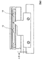
- a scale 1 is over (Not shown) holding elements connected to an object 9.
- a scanning unit which consists of a measuring head 3, a measuring carriage 4 and two rollers 5 slides during the measurement process in a groove of the object 9.
- connection points 7, 8 Via two connection points 7, 8, a coupling device 2 is fixed on both sides to the Measuring car 4 connected.
- the junctions 7, 8 are generally in the Precision mechanics usual types of attachment, such as Laser welding, implemented. she but can also optionally be represented by positive connections become.
- a driver 10 which via suitable connecting elements, e.g. Screws 15 another object 11 is attached to the coupling device 2 via a Coupling point 6 is positively connected.
- This crosspoint 6 can also e.g. can be created by laser welding.
- the coupling device 2 shown in Fig. 1 has in the longitudinal direction x between the Junctions 7 and 8 have a different cross section. With more even Material thickness is the coupling device with a widening in some places provided, whereby the bending stress in the coupling device in the area of Broadening is reduced.
- the condition of a same resulting spring constant at the coupling point 6 can be met.
- material for the coupling device 2 preferably comes spring steel, e.g. CrMo steel, for use.
- the coupling device 2 shows another embodiment for the invention Length measuring device shown in the, in contrast to the embodiment 1, the coupling device 2 has two expansion zones 12 and 13, the are advantageously sinusoidal or cosine-shaped.
- the coupling point 6, as shown in Fig. 1 is arranged at a point where the resulting spring constants between this point and the one connection point 7 on the one hand and the other Junction 8, on the other hand, are approximately the same size.
- Permissible Deviations / differences in the spring constants result from the permitted ones Measurement error deadlines.
- the embodiment of a measuring device shown only in principle in FIG. 3 shows a displacement of the coupling point 6 by an amount ⁇ z1.
- the dynamic state that is to say when the scanning unit in object 9 is traversed during the measurement, there is a further displacement of the coupling point 6 by the amount ⁇ z2, this being caused by encapsulation radii and capsule sagging.
- the coupling point 6 Due to the fixed connection on both sides of the deflectable elastic coupling device 2 and the symmetrical position of the coupling point 6 with respect to the spring constants, the coupling point 6 is shifted by ⁇ z1 and ⁇ z2 on a straight line 14 which is perpendicular to the connecting line between the connecting points 7 and 8.
- the measurement error ⁇ x2 dyn 0 and there is no measurement error.
- the expansion zones 12, 13 are, for example, sinusoidal and the cross section of the coupling device 2 is dimensioned such that a predetermined one permissible measurement error, caused by the acceleration force Fx, not is exceeded. This results in a minimum stiffness in the longitudinal direction x (Direction of travel) guaranteed.
Landscapes
- Physics & Mathematics (AREA)
- General Physics & Mathematics (AREA)
- A Measuring Device Byusing Mechanical Method (AREA)
- Length Measuring Devices With Unspecified Measuring Means (AREA)
- Length-Measuring Instruments Using Mechanical Means (AREA)
Claims (8)
- Dispositif de mesure de longueur comprenant une règle (1) avec une graduation et une unité de lecture avec une tête de mesure (3) et un chariot de mesure (4), dans lequel la règle (1) peut être reliée à un objet (9) par des éléments de maintien et la graduation peut être explorée par l'unité de lecture dans la direction longitudinale X, l'unité de lecture pouvant être reliée par un entraíneur (10) à un autre objet (11) et l'unité de lecture étant couplée avec l'entraíneur (10) par un point de couplage (6) d'un dispositif de couplage (2) élastique à déviation, caractérisé par le fait que le dispositif de couplage (2) est fixé au chariot de mesure (4) de l'unité de lecture en deux emplacements de liaison (7, 8) et que le point de couplage (6) est disposé sur le dispositif de couplage (2) entre ces emplacements de liaison (7, 8).
- Dispositif de mesure de longueur suivant la revendication 1, caractérisé par le fait que les emplacements de liaison (7, 8) du dispositif de couplage (2) sont reliés de façon fixe au chariot de mesure (4).
- Dispositif de mesure de longueur suivant la revendication 1 ou 2, caractérisé par le fait que le point de couplage (6) est disposé en un endroit auquel les constantes de ressort résultantes entre cet endroit et l'un des emplacements de liaison (7) d'une part et entre cet endroit et l'autre emplacement de liaison (8) d'autre part sont de valeurs sensiblement égales.
- Dispositif de mesure de longueur suivant l'une quelconque des revendications 1 à 3, caractérisé par le fait que le dispositif de couplage (2) contient des zones de dilatation (12, 13).
- Dispositif de mesure de longueur suivant la revendication 4, caractérisé par le fait que les zones de dilatation (12, 13) s'étendent selon une forme sinusoïdale dans la direction longitudinale X.
- Dispositif de mesure de longueur suivant l'une quelconque des revendications 1 à 5, caractérisé par le fait que le dispositif de couplage (2) présente dans la direction longitudinale X entre les deux emplacements de liaison (7, 8) des sections transversales différentes.
- Dispositif de mesure de longueur suivant l'une quelconque des revendications 1 à 5, caractérisé par le fait que les sections transversales du dispositif de couplage (2) situées dans la direction longitudinale X entre les emplacements de liaison (7, 8) présentent, pour une même distance par rapport à l'emplacement de couplage (6), les mêmes aires de section et/ou formes de section.
- Dispositif de mesure de longueur suivant l'une quelconque des revendications 1 à 5, caractérisé par le fait que le dispositif de couplage (2) est en acier à ressort.
Applications Claiming Priority (3)
| Application Number | Priority Date | Filing Date | Title |
|---|---|---|---|
| DE19543647A DE19543647C2 (de) | 1995-11-23 | 1995-11-23 | Längenmeßeinrichtung zur Messung der Relativlage zweier Objekte |
| DE19543647 | 1995-11-23 | ||
| PCT/EP1996/005078 WO1997019324A1 (fr) | 1995-11-23 | 1996-11-18 | Appareil de mesure de la longueur servant a mesurer la position relative de deux objets |
Publications (2)
| Publication Number | Publication Date |
|---|---|
| EP0805954A1 EP0805954A1 (fr) | 1997-11-12 |
| EP0805954B1 true EP0805954B1 (fr) | 2001-04-11 |
Family
ID=7778199
Family Applications (1)
| Application Number | Title | Priority Date | Filing Date |
|---|---|---|---|
| EP96939095A Expired - Lifetime EP0805954B1 (fr) | 1995-11-23 | 1996-11-18 | Appareil de mesure de la longueur servant a mesurer la position relative de deux objets |
Country Status (6)
| Country | Link |
|---|---|
| US (1) | US5924214A (fr) |
| EP (1) | EP0805954B1 (fr) |
| JP (1) | JP3819433B2 (fr) |
| AT (1) | ATE200573T1 (fr) |
| DE (2) | DE19543647C2 (fr) |
| WO (1) | WO1997019324A1 (fr) |
Families Citing this family (6)
| Publication number | Priority date | Publication date | Assignee | Title |
|---|---|---|---|---|
| US6029363A (en) * | 1998-04-03 | 2000-02-29 | Mitutoyo Corporation | Self-calibrating position transducer system and method |
| DE19943729A1 (de) * | 1999-09-03 | 2001-03-08 | Heidenhain Gmbh Dr Johannes | Wegmeßsystem |
| US6487787B1 (en) | 2001-08-03 | 2002-12-03 | Mitutoyo Corporation | System and method for determination of error parameters for performing self-calibration and other functions without an external position reference in a transducer |
| DE10204611B4 (de) * | 2002-02-05 | 2007-04-05 | Dr. Johannes Heidenhain Gmbh | Verfahren und Vorrichtung zum Anbringen eines Maßstabes oder Maßstabträgers |
| US20060168837A1 (en) * | 2005-02-01 | 2006-08-03 | Muir Arthur M | Zero set scale |
| DE102008005384A1 (de) * | 2008-01-22 | 2009-07-23 | Dr. Johannes Heidenhain Gmbh | Längenmesseinrichtung |
Family Cites Families (19)
| Publication number | Priority date | Publication date | Assignee | Title |
|---|---|---|---|---|
| DE7507398U (de) * | 1975-07-31 | Heidenhain J Gmbh | LängenmeBe inrichtu ng | |
| US4152837A (en) * | 1975-03-08 | 1979-05-08 | Dr. Johannes Heidenhain Gmbh. | Length measuring device |
| DE2611459C3 (de) * | 1976-03-18 | 1978-09-21 | Dr. Johannes Heidenhain Gmbh, 8225 Traunreut | Längenmeßeinrichtung |
| US4198757A (en) * | 1976-07-09 | 1980-04-22 | Dr. Johannes Heidenhain Gmbh | Fastening apparatus for longitudinal measuring system |
| DE2810341C2 (de) * | 1978-03-10 | 1980-01-31 | Dr. Johannes Heidenhain Gmbh, 8225 Traunreut | Längenmeßeinrichtung |
| US4569137A (en) * | 1983-06-07 | 1986-02-11 | Mitutoyo Mfg. Co., Ltd. | Linear scale type displacement measuring device and main scale attaching method thereof |
| DE8525587U1 (de) * | 1985-09-07 | 1987-01-08 | Robert Bosch Gmbh, 7000 Stuttgart | Wegmeßeinrichtung |
| JPH052804Y2 (fr) * | 1986-05-21 | 1993-01-25 | ||
| DE3625795A1 (de) * | 1986-07-30 | 1988-02-04 | Heidenhain Gmbh Dr Johannes | Laengenmesseinrichtung |
| DE3711070A1 (de) * | 1987-04-02 | 1988-11-24 | Heidenhain Gmbh Dr Johannes | Laengen- oder winkelmesseinrichtung |
| DE3908260C1 (fr) * | 1989-03-14 | 1990-05-31 | Dr. Johannes Heidenhain Gmbh, 8225 Traunreut, De | |
| DE3929629A1 (de) * | 1989-09-06 | 1991-03-07 | Zeiss Carl Fa | Laengen- oder winkelmesseinrichtung |
| DE4021919C2 (de) * | 1990-07-10 | 1995-06-08 | Heidenhain Gmbh Dr Johannes | Maßverkörperung |
| ATE108271T1 (de) * | 1991-05-11 | 1994-07-15 | Heidenhain Gmbh Dr Johannes | Positionsmesseinrichtung. |
| DE4212970A1 (de) * | 1992-04-18 | 1993-10-21 | Heidenhain Gmbh Dr Johannes | Längenmeßeinrichtung |
| JP3134590B2 (ja) * | 1993-05-13 | 2001-02-13 | ソニー・プレシジョン・テクノロジー株式会社 | スケール装置 |
| DE4406797C2 (de) * | 1994-03-02 | 1997-11-27 | Heidenhain Gmbh Dr Johannes | Positionsmeßeinrichtung |
| DE4406798C2 (de) * | 1994-03-02 | 1997-11-27 | Heidenhain Gmbh Dr Johannes | Positionsmeßeinrichtung |
| DE4406799C2 (de) * | 1994-03-02 | 1997-11-06 | Heidenhain Gmbh Dr Johannes | Positionsmeßeinrichtung |
-
1995
- 1995-11-23 DE DE19543647A patent/DE19543647C2/de not_active Expired - Fee Related
-
1996
- 1996-11-18 US US08/860,262 patent/US5924214A/en not_active Expired - Lifetime
- 1996-11-18 WO PCT/EP1996/005078 patent/WO1997019324A1/fr not_active Ceased
- 1996-11-18 EP EP96939095A patent/EP0805954B1/fr not_active Expired - Lifetime
- 1996-11-18 JP JP51938097A patent/JP3819433B2/ja not_active Expired - Fee Related
- 1996-11-18 AT AT96939095T patent/ATE200573T1/de not_active IP Right Cessation
- 1996-11-18 DE DE59606768T patent/DE59606768D1/de not_active Expired - Lifetime
Also Published As
| Publication number | Publication date |
|---|---|
| JP3819433B2 (ja) | 2006-09-06 |
| ATE200573T1 (de) | 2001-04-15 |
| JPH11500230A (ja) | 1999-01-06 |
| DE19543647A1 (de) | 1997-05-28 |
| US5924214A (en) | 1999-07-20 |
| DE19543647C2 (de) | 2000-05-04 |
| DE59606768D1 (de) | 2001-05-17 |
| WO1997019324A1 (fr) | 1997-05-29 |
| EP0805954A1 (fr) | 1997-11-12 |
Similar Documents
| Publication | Publication Date | Title |
|---|---|---|
| EP0709655A2 (fr) | Guidage | |
| DE102007044128A1 (de) | Längenmesseinrichtung | |
| EP0805954B1 (fr) | Appareil de mesure de la longueur servant a mesurer la position relative de deux objets | |
| EP3705850A1 (fr) | Dispositif doté d'un support principal, d'un support intermédiaire agencé sur le support principal et d'une cale agencé sur le support intermédiaire | |
| EP0951967A1 (fr) | Dispositif pour déterminer la précision de la position sur une voie des éléments mobiles de machine | |
| AT408729B (de) | Werkzeugspannvorrichtung für ein formwerkzeug, insbesondere einer abkantpresse | |
| EP0314814A1 (fr) | Machine de mesure a coordonnees | |
| DE8621056U1 (de) | Gekapselte Positionsmeßeinrichtung | |
| EP4030147A1 (fr) | Appareil de mesure de longueur | |
| WO2001016564A1 (fr) | Roulement lineaire comportant une unite servant a effectuer une mesure | |
| EP0077318A2 (fr) | Dispositif pour mesurer deux chemins de rouleaux opposés d'une installation de coulée continue | |
| EP1920876A1 (fr) | Support pour une broche d'outil | |
| DE10229885A1 (de) | Verfahren und Vorrichtung zum Anbringen eines Maßstabs oder Maßstabträgers oder einer Maßstabführung | |
| DE1157877B (de) | Vorrichtung zur Geradfuehrung eines verschiebbaren Organs, z.B. Taster, Schlitten od. dgl. bei Praezisionsmaschinen | |
| DE102017201230A1 (de) | Linearbewegungsvorrichtung mit Lebensdauerüberwachung | |
| DE29522136U1 (de) | Längenmeßeinrichtung zur Messung der Relativlage zweier Objekte | |
| EP3228993B1 (fr) | Dispositif de mesure de longueur | |
| EP0459294A2 (fr) | Dispositif pour mesurer une position | |
| EP1336815A2 (fr) | Dispositif de balayage pour la mesure des machines de production | |
| EP3961159B1 (fr) | Dispositif de mesure de position | |
| DE69714762T2 (de) | Optisches messlineal für linearmessungen mit einer führung für den messwagen des optischen ablesekopfes | |
| DE10214426A1 (de) | Längenmesseinrichtung und Linearführungseinheit | |
| DE3128795A1 (de) | "verfahren und vorrichtung zum messen wenigstens einer komponente der auf einen traeger einwirkenden belastungen" | |
| DE3509502A1 (de) | Positionsfuehleinrichtung | |
| DE1698006A1 (de) | Aus Einzelstuecken zusammengesetzter Laengenmassstab |
Legal Events
| Date | Code | Title | Description |
|---|---|---|---|
| PUAI | Public reference made under article 153(3) epc to a published international application that has entered the european phase |
Free format text: ORIGINAL CODE: 0009012 |
|
| 17P | Request for examination filed |
Effective date: 19970411 |
|
| AK | Designated contracting states |
Kind code of ref document: A1 Designated state(s): AT CH DE GB IT LI |
|
| RAP1 | Party data changed (applicant data changed or rights of an application transferred) |
Owner name: DR. JOHANNES HEIDENHAIN GMBH |
|
| 17Q | First examination report despatched |
Effective date: 20000208 |
|
| GRAG | Despatch of communication of intention to grant |
Free format text: ORIGINAL CODE: EPIDOS AGRA |
|
| GRAG | Despatch of communication of intention to grant |
Free format text: ORIGINAL CODE: EPIDOS AGRA |
|
| GRAH | Despatch of communication of intention to grant a patent |
Free format text: ORIGINAL CODE: EPIDOS IGRA |
|
| GRAH | Despatch of communication of intention to grant a patent |
Free format text: ORIGINAL CODE: EPIDOS IGRA |
|
| ITF | It: translation for a ep patent filed | ||
| GRAA | (expected) grant |
Free format text: ORIGINAL CODE: 0009210 |
|
| AK | Designated contracting states |
Kind code of ref document: B1 Designated state(s): AT CH DE GB IT LI |
|
| REF | Corresponds to: |
Ref document number: 200573 Country of ref document: AT Date of ref document: 20010415 Kind code of ref document: T |
|
| REG | Reference to a national code |
Ref country code: CH Ref legal event code: NV Representative=s name: TROESCH SCHEIDEGGER WERNER AG Ref country code: CH Ref legal event code: EP |
|
| REF | Corresponds to: |
Ref document number: 59606768 Country of ref document: DE Date of ref document: 20010517 |
|
| GBT | Gb: translation of ep patent filed (gb section 77(6)(a)/1977) |
Effective date: 20010615 |
|
| REG | Reference to a national code |
Ref country code: GB Ref legal event code: IF02 |
|
| PLBE | No opposition filed within time limit |
Free format text: ORIGINAL CODE: 0009261 |
|
| STAA | Information on the status of an ep patent application or granted ep patent |
Free format text: STATUS: NO OPPOSITION FILED WITHIN TIME LIMIT |
|
| 26N | No opposition filed | ||
| PGFP | Annual fee paid to national office [announced via postgrant information from national office to epo] |
Ref country code: AT Payment date: 20061113 Year of fee payment: 11 |
|
| PG25 | Lapsed in a contracting state [announced via postgrant information from national office to epo] |
Ref country code: AT Free format text: LAPSE BECAUSE OF NON-PAYMENT OF DUE FEES Effective date: 20071118 |
|
| PGFP | Annual fee paid to national office [announced via postgrant information from national office to epo] |
Ref country code: IT Payment date: 20101126 Year of fee payment: 15 Ref country code: GB Payment date: 20101118 Year of fee payment: 15 |
|
| PGFP | Annual fee paid to national office [announced via postgrant information from national office to epo] |
Ref country code: CH Payment date: 20111123 Year of fee payment: 16 |
|
| PGFP | Annual fee paid to national office [announced via postgrant information from national office to epo] |
Ref country code: DE Payment date: 20121121 Year of fee payment: 17 |
|
| REG | Reference to a national code |
Ref country code: CH Ref legal event code: PL |
|
| GBPC | Gb: european patent ceased through non-payment of renewal fee |
Effective date: 20121118 |
|
| PG25 | Lapsed in a contracting state [announced via postgrant information from national office to epo] |
Ref country code: CH Free format text: LAPSE BECAUSE OF NON-PAYMENT OF DUE FEES Effective date: 20121130 Ref country code: LI Free format text: LAPSE BECAUSE OF NON-PAYMENT OF DUE FEES Effective date: 20121130 |
|
| PG25 | Lapsed in a contracting state [announced via postgrant information from national office to epo] |
Ref country code: IT Free format text: LAPSE BECAUSE OF NON-PAYMENT OF DUE FEES Effective date: 20121118 |
|
| PG25 | Lapsed in a contracting state [announced via postgrant information from national office to epo] |
Ref country code: GB Free format text: LAPSE BECAUSE OF NON-PAYMENT OF DUE FEES Effective date: 20121118 |
|
| PG25 | Lapsed in a contracting state [announced via postgrant information from national office to epo] |
Ref country code: DE Free format text: LAPSE BECAUSE OF NON-PAYMENT OF DUE FEES Effective date: 20140603 |
|
| REG | Reference to a national code |
Ref country code: DE Ref legal event code: R119 Ref document number: 59606768 Country of ref document: DE Effective date: 20140603 |