EP0806162A1 - Dispositif de guidage pour tiroirs - Google Patents
Dispositif de guidage pour tiroirs Download PDFInfo
- Publication number
- EP0806162A1 EP0806162A1 EP97890074A EP97890074A EP0806162A1 EP 0806162 A1 EP0806162 A1 EP 0806162A1 EP 97890074 A EP97890074 A EP 97890074A EP 97890074 A EP97890074 A EP 97890074A EP 0806162 A1 EP0806162 A1 EP 0806162A1
- Authority
- EP
- European Patent Office
- Prior art keywords
- drawer
- guide
- rail
- roller
- support lever
- Prior art date
- Legal status (The legal status is an assumption and is not a legal conclusion. Google has not performed a legal analysis and makes no representation as to the accuracy of the status listed.)
- Granted
Links
- 238000005096 rolling process Methods 0.000 claims abstract 2
- 230000000284 resting effect Effects 0.000 claims description 3
- 238000011144 upstream manufacturing Methods 0.000 claims description 2
- 230000007704 transition Effects 0.000 claims 1
- 238000006073 displacement reaction Methods 0.000 description 4
- 230000005484 gravity Effects 0.000 description 4
- 238000010276 construction Methods 0.000 description 3
- 230000001771 impaired effect Effects 0.000 description 2
- 238000003780 insertion Methods 0.000 description 2
- 230000037431 insertion Effects 0.000 description 2
- 235000004443 Ricinus communis Nutrition 0.000 description 1
- 230000002349 favourable effect Effects 0.000 description 1
Images


Classifications
-
- A—HUMAN NECESSITIES
- A47—FURNITURE; DOMESTIC ARTICLES OR APPLIANCES; COFFEE MILLS; SPICE MILLS; SUCTION CLEANERS IN GENERAL
- A47B—TABLES; DESKS; OFFICE FURNITURE; CABINETS; DRAWERS; GENERAL DETAILS OF FURNITURE
- A47B88/00—Drawers for tables, cabinets or like furniture; Guides for drawers
- A47B88/40—Sliding drawers; Slides or guides therefor
- A47B88/433—Drawers with a couple of pivotally retractable, roller-supporting arms at the rear of the drawer, e.g. for curved slides or guides
Definitions
- the invention relates to a drawer slide with a body rail which essentially forms a U-profile, a drawer rail resting on a roller in the front end region of the body rail, which carries a roller which rolls on a lower guide web of the body rail in the rear end region and via a hinged support lever the rear wall of the drawer can be extended, as well as with a link guide provided in the rear end area of the mounting flange of the carcass rail for the support lever that can be swiveled between a swung-up rest position and a swiveled-down, limited working position an upper guide web of the body rail cooperating support role.
- the cross-sectionally Z-shaped drawer slide also rests on a roller mounted in the front end area of the body rail above the upper guide web, via which part of the drawer weight is removed.
- the rest of the load is transferred to the cabinet rail via the rear roller of the drawer rail, as long as the center of gravity of the drawer is behind the roller of the cabinet rail. If the center of gravity of the drawer is moved over the castor of the cabinet rail when the drawer is pulled out, the support roller of the support lever on the upper guide bar prevents the drawer from tipping, which can thus be extended until the roller of the drawer rail reaches the end of the cabinet rail. Because of the arrangement of the roller of the cabinet rail above the upper guide web, the two rollers of the cabinet rail and the drawer rail can lie one above the other when the drawer is fully extended.
- the body rail forms a link guide for the support lever in the rear area of the fastening flange, which is extended beyond the upper guide web and which engages into the link via a guide bolt projecting laterally against the link guide .
- a disadvantage of this known drawer guide is, above all, that because of the body rail running laterally next to the drawer, a comparatively large gap must be provided between the side walls of the drawer and the inner wall of the body, which limits the possible drawer width.
- the invention is therefore based on the object of designing a drawer guide of the type described at the beginning with simple constructional means so that the largest possible drawer width can be ensured.
- the functionality of the drawer slide should not be impaired by improper cabinet rail attachment.
- the invention achieves the stated object in that the drawer rail provided in a manner known per se on the underside of the drawer runs at least essentially within the body rail, the fastening flange with its outer leg and the lower web with its connecting web connecting the outer and inner legs Guide web forms, while the upper guide web consists of an angled against the mounting flange edge web of the inner leg of the body rail, on which the roller for the drawer rail is mounted.
- the drawer rail can be provided on the underside of the drawer despite the attachment of the cabinet rail to the side cabinet inner wall, the lateral distance between the drawer and the cabinet interior wall can be kept small because the rollers and support rollers are below the drawer and the lateral distance between the drawer and the inner wall of the cabinet only has to be large enough to accommodate the slide guide, which can be kept comparatively narrow.
- the height of the drawer guide below the drawer is essentially from Diameter of the rollers determined.
- the running or support rollers assigned to the individual rails need only be overlapped by a web of the other rail.
- rollers of the body rail on the side of the inner leg facing the fastening flange which forms the upper guide web with an angled edge web at least for the support roller of the support lever, lie one behind the other in the pull-out direction essentially without lateral displacement, which avoids torrential loads on the rails .
- rollers With conventional drawers with side walls protruding downward from the floor, there is an advantageous arrangement of these rollers in the floor area behind the side walls.
- the support lever can be loaded by a spring in the sense of pivoting up.
- this spring load causes a weight balance for the lever and, on the other hand, supports the drawer being drawn into the closed position.
- this spring load secures the rest position of the support lever when the drawer rail is inserted into the body rail, which therefore only has to have an insertion opening adapted to the roller of the drawer rail. In such a case, however, it must be ensured that the guide body of the support lever engages in the link guide when the drawer is inserted.
- the link guide in the height region of the guide body of the pivoted-up support lever can have an upstream catch guide for the guide body which merges into the link, so that when the drawer is subsequently pulled out, the support lever is properly pivoted into the stop-limited working position via the guide body engaging in the link, so that when the drawer is pushed in repeatedly, it is only moved along the slide guide.
- particularly simple constructional relationships result when the catch guide protrudes against the backdrop against the drawer.
- the guide body of the support lever is first moved past this catch guide using, for example, an elastic behavior that results when the support lever is pivoted up, in order to then move it against the backdrop along the catch guide when the drawer is pulled out and to be inserted into it due to the residual spring that is still present .
- the link guide can have a stop for the guide body of the support lever at its end.
- the guide body for the link guide can advantageously consist of a guide roller which projects against the link guide and can be gripped by the link, which cannot slide off the link guide due to this overlapping by the link.
- a favorable embodiment results from the fact that the conical guide roller is mounted inclined downwards in the support lever in relation to the mounting flange of the body rail.
- the link can have a guide surface which is adapted to the cross section and is inclined. Apart from this, such a guide roller provides an advantageous contact surface in order to move the guide roller past the catch guide of the guide link when the drawer is inserted due to the inherent elasticity of the support lever or a corresponding spring load.
- the support lever can advantageously be mounted in an end piece which is connected to the drawer rail and at the same time carries the roller of the drawer rail. If such an end piece is provided, the support lever linkage can be disregarded in the structural design of the drawer rail.
- the drawer rail and the carcass rail can thus also be used for single pull-outs, in particular if the link guide forms a component which is separate from the carcass rail but can be connected to the carcass rail.
- the end piece can also be attached to the rear wall of the drawer.
- the drawer rail can have an angled edge web which is overlapped by a safety stop in the front end region of the body rail. Since an edge web of the drawer rail interacts with this safety stop, the anti-lift device for the drawer is provided over a wide area of the pull-out.
- the roller of the drawer rail can be arranged substantially without lateral displacement in relation to the roller of the body rail. However, this limits the possible extension length, because the roller of the drawer rail cannot be moved past the roller of the carcase rail. If the bar of the body rail forms a track for the roller of the drawer rail that is offset from its roller against the mounting flange, the roller of the drawer rail can be moved past the roller of the body rail up to its height, which allows a maximum extension length.
- the displacement of the roller of the shop rail makes no difficulties, especially if it is stored in a separate end piece, so that the bearing of the roller can be disregarded when designing the shop rail.
- the link guide for the mounting leg of the carcass rail Although it is advisable to use the link guide for the mounting leg of the carcass rail, a mounting leg that runs the entire length of the rail is recommended, but a construction can also be used in which the mounting leg of the carcass rail consists of mounting brackets connected to the web.
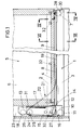
- the drawer guide shown has a body rail 1 which essentially forms a U-profile, the outer leg 2 of which forms a fastening flange and which engages with its inner leg 3 behind the side wall 6 which projects downwards over the base 4 of the drawer 5.
- a roller 7 for a drawer rail 8 is provided, which is attached to the underside of the drawer 5 and rests on the roller 7 of the body rail 1 with a runway 9.
- an end piece 10 which carries a roller 11 which rolls on the web 12 of the carcass rail 1 connecting the legs 2 and 3.
- a support lever 13 is also pivotally mounted about a horizontal axis 14.
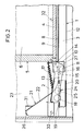
- the support lever 13 can be pivoted between a swiveled-up rest position shown in FIG. 1 and a swung-down working position (FIG. 3).
- the pivoted-away working position is secured by a stop 15 which engages in a stop recess 16 of the end piece 10.
- a spring 17 is articulated, which loads the support lever 13 in the sense of pivoting up into the rest position.
- a support roller 18 is mounted, which cooperates with an upper guide web formed by an angled edge web 19 of the inner leg 3 of the body rail 1.
- the drawer rail 8 is thus on the one hand via the front roller 7 of the body rail 1 and on the other hand via the rear roller 11 of the drawer rail on the web 12 of the body rail 1 and in the working position of the support lever 13 via the support roller 18 on the upper edge web 19 supported.
- the support roller 18 of the support lever 13 assumes no support force. Only when the drawer center of gravity is moved beyond the front roller 7 of the body rail 1 when the drawer 5 is pulled out and the drawer 5 is loaded by a tilting moment which acts in the sense of the roller 11 lifting off the web 12 of the body rail 1, does this tilting moment occur via the Support roller 18 of the support lever 13 resting against the stop is removed from the angled edge web 19 of the body rail.
- the roller 7 of the carcass rail 1 and the support roller 18 of the support lever 13 lie one behind the other without substantial lateral displacement in the pull-out direction, so that no corresponding torrential moment is exerted on the rails 1 and 8.
- the roller 11 of the drawer rail 8 could roll in the area of the catwalk of the support roller 18 on the web 12 of the body rail 1.
- Such a construction would, however, require that the roller 11 cannot be moved laterally past the roller 7 of the body rail 1 up to its height. For this reason, the web 12 of the carcass rail 1 forms a separate catwalk 20 for the caster 11 which is laterally offset in the end piece 10 relative to the caster 7.
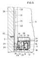
- the body rail 1 in the area of the mounting flange 2 is assigned a link guide 21, the link 22 of which is formed by a guide web projecting against the drawer 5, which projects into the space between the inner wall 23 of the body and the side wall 6 of the drawer 5.
- a guide body 24 of the support lever 13 cooperates with this guide link 21 in the form of a conical guide roller 25, which is supported in the support lever 13 in a downward inclination in accordance with FIGS. 4 and 5 relative to the mounting flange 2 of the body rail 1.
- the link 22 Since, in addition, the guide web of the link 22 is correspondingly inclined in cross section, the link 22 results in a lateral guide for the guide roller 25, which prevents the guide roller 25 from running off the link guide 21.
- the spring 17 guides the guide roller 25 in the area of the slide guide 21 during the insertion and removal of the drawer 5 pressed against the backdrop 22 and the support lever 13 gradually swung up or down, as indicated in FIG. 2.
- the upper edge web 19 of the body rail 1 must be interrupted in this section so that the support roller 18 cannot hinder the pivoting of the support lever 13. In the inserted end position, in which the support lever 13 according to FIG. 1 assumes the swung-up rest position, the guide roller 25 of the support lever 13 bears against an end stop 26 of the link guide 21.
- the support lever 13 When the drawer 5 is pulled out, the support lever 13 is pivoted against the force of the spring 17 along the link guide 21 into the working position until the support roller 18 passes under the upper edge web 19 of the body rail and the guide roller 25 can run off the link 22.
- the pull-out movement of the drawer is only limited when a limit stop 27 formed from an angled tongue of the end piece 10 strikes the front roller 7 of the carcass rail 1. In this extended position, the roller 11 on the drawer rail side lies essentially next to the roller 7 of the carcass rail 1.
- a securing stop 28 which engages over an angled edge web 29 of the drawer rail 8, as can be seen in particular from FIG. 6.
- This securing stop 28 is formed by an inwardly angled attachment tab of a front end wall 30, which connects the legs 2 and 3 of the carcass rail 1 to one another in the web area.
- the drawer rail 8 To insert the drawer 5, the drawer rail 8 must be inserted into the body rail 1 so that the catwalk 9 of the drawer rail 8 rests on the roller 7 of the body rail 1. So that the support roller 18 of the support lever 13 does not have to be threaded behind the roller 7 of the carcass rail 1 under the upper edge web 19, the support lever 13 remains in its rest position held by the spring 17. However, this means that the guide body 24 can engage securely in the guide link 21 when the drawer 5 is inserted.
- a guide guide 31 is arranged in front of the guide link 21 in the height region of the guide body 24 of the pivoted-up support body 13 and protrudes beyond the link 22 according to FIGS. 4 and 5.
- the guide body 24 of the catch guide 31 can yield inward in order to then reach behind the catch guide 31 formed from a guide web, when the drawer 5 is subsequently pulled out, the guide body 24 is moved along the catch guide 31 against the subsequent one Backlash 22, in which he resiliently engages due to the remaining tension.
- the inclined position of the guide roller 25 makes it easier to move past the catch guide 31. If the inherent elasticity is not sufficient for a flexible deflection of the guide roller 25 in the area of the catch guide 31, the guide roller 25 could also be axially sprung. In any case, it must be ensured that in the pivoted-down working position, the support lever 13 allows sufficient lateral guidance of the drawer 5, which can generally be easily ensured with a corresponding stop position.
- the fastening screws 32 lie outside the movement paths of the support, running and guide rollers in the region of the outer leg 2 of the carcass rail 1, so that the functionality of the drawer guide cannot be impaired even then when the screw heads protrude beyond the mounting flange.
- the freely accessible, free leg 2 of the body rail 1 facilitates its assembly.
Landscapes
- Drawers Of Furniture (AREA)
- Bearings For Parts Moving Linearly (AREA)
Applications Claiming Priority (3)
| Application Number | Priority Date | Filing Date | Title |
|---|---|---|---|
| AT0081196A AT406438B (de) | 1996-05-07 | 1996-05-07 | Schubladenführung |
| AT811/96 | 1996-05-07 | ||
| AT81196 | 1996-05-07 |
Publications (2)
| Publication Number | Publication Date |
|---|---|
| EP0806162A1 true EP0806162A1 (fr) | 1997-11-12 |
| EP0806162B1 EP0806162B1 (fr) | 2001-03-28 |
Family
ID=3500272
Family Applications (1)
| Application Number | Title | Priority Date | Filing Date |
|---|---|---|---|
| EP97890074A Expired - Lifetime EP0806162B1 (fr) | 1996-05-07 | 1997-04-23 | Dispositif de guidage pour tiroirs |
Country Status (5)
| Country | Link |
|---|---|
| US (1) | US5895102A (fr) |
| EP (1) | EP0806162B1 (fr) |
| AT (1) | AT406438B (fr) |
| DE (1) | DE59703216D1 (fr) |
| ES (1) | ES2155666T3 (fr) |
Cited By (2)
| Publication number | Priority date | Publication date | Assignee | Title |
|---|---|---|---|---|
| WO2001087743A1 (fr) * | 2000-05-09 | 2001-11-22 | Talleres Lupiñen, S.L. | Etagere coulissante |
| CN114014386A (zh) * | 2021-10-12 | 2022-02-08 | 深圳市金利源净水设备有限公司 | 一种净水机的废水回收装置 |
Families Citing this family (11)
| Publication number | Priority date | Publication date | Assignee | Title |
|---|---|---|---|---|
| US6481812B1 (en) | 2000-09-19 | 2002-11-19 | Grass America, Inc. | Undermount drawer guide assembly |
| US6360900B1 (en) | 2000-09-26 | 2002-03-26 | Nstor Corporation | Data storage chassis with adjustable rack mounting |
| AT5674U3 (de) * | 2002-07-22 | 2003-05-26 | Fulterer Gmbh | Gedämpfte selbsteinzugseinrichtung |
| DE20306212U1 (de) * | 2003-04-23 | 2003-06-18 | Julius Blum Ges.m.b.H., Höchst | Ausziehführungsgarnitur für Schubladen od.dgl. |
| USD492507S1 (en) | 2003-08-22 | 2004-07-06 | Suncast Corporation | Three drawer plastic cabinet |
| US20050168115A1 (en) * | 2004-02-04 | 2005-08-04 | Brian Moon | Drawer cabinet storage kit |
| US20050229360A1 (en) * | 2004-04-15 | 2005-10-20 | Lowe Mark J | Hinge |
| US7527342B2 (en) * | 2005-05-04 | 2009-05-05 | Royal Hardware, Inc. | Drawer stabilizer and self-closer mechanism |
| US20070080614A1 (en) * | 2005-10-07 | 2007-04-12 | Suncast Corporation | Drawer cabinet storage kit |
| US8016374B2 (en) * | 2005-11-10 | 2011-09-13 | Grass Gmbh | Pull-out slide for drawers and drawer |
| CN112057657B (zh) * | 2020-10-14 | 2025-04-01 | 杭州老板电器股份有限公司 | 抽屉滑轨、柜门组件及消毒柜 |
Citations (4)
| Publication number | Priority date | Publication date | Assignee | Title |
|---|---|---|---|---|
| CH195282A (de) * | 1937-04-03 | 1938-01-31 | Union Kassenfabrik A G | Schrank mit in Führungen laufenden Schiebekörpern. |
| DE2946113A1 (de) * | 1979-11-15 | 1981-05-21 | Erich 6483 Bad Soden-Salmünster Löhnert | Auszugsbeschlag fuer einen schubkasten |
| DE4027468A1 (de) * | 1990-08-30 | 1992-03-05 | Willach Gmbh Geb | Schubladenfuehrung |
| DE9413108U1 (de) * | 1994-08-17 | 1995-01-12 | Grass AG, Höchst, Vorarlberg | Schubladenführung |
Family Cites Families (5)
| Publication number | Priority date | Publication date | Assignee | Title |
|---|---|---|---|---|
| US1178877A (en) * | 1915-03-31 | 1916-04-11 | Gen Fireproofing Co | Drawer suspension for furniture. |
| CH240433A (de) * | 1944-05-09 | 1945-12-31 | Union Kassenfabrik Ag | Auszugseinrichtung für Schubladen und dergleichen. |
| US2575566A (en) * | 1946-02-21 | 1951-11-20 | Shand Harold | Extensible side support for sliding drawers and the like |
| DE2908336A1 (de) * | 1978-04-05 | 1979-10-18 | Blum Gmbh Julius | Ausziehfuehrung fuer schubladen o.dgl. |
| DE59107521D1 (de) * | 1991-12-06 | 1996-04-11 | Willach Gmbh Geb | Schubladenführung |
-
1996
- 1996-05-07 AT AT0081196A patent/AT406438B/de not_active IP Right Cessation
-
1997
- 1997-04-22 US US08/847,663 patent/US5895102A/en not_active Expired - Fee Related
- 1997-04-23 DE DE59703216T patent/DE59703216D1/de not_active Expired - Fee Related
- 1997-04-23 EP EP97890074A patent/EP0806162B1/fr not_active Expired - Lifetime
- 1997-04-23 ES ES97890074T patent/ES2155666T3/es not_active Expired - Lifetime
Patent Citations (4)
| Publication number | Priority date | Publication date | Assignee | Title |
|---|---|---|---|---|
| CH195282A (de) * | 1937-04-03 | 1938-01-31 | Union Kassenfabrik A G | Schrank mit in Führungen laufenden Schiebekörpern. |
| DE2946113A1 (de) * | 1979-11-15 | 1981-05-21 | Erich 6483 Bad Soden-Salmünster Löhnert | Auszugsbeschlag fuer einen schubkasten |
| DE4027468A1 (de) * | 1990-08-30 | 1992-03-05 | Willach Gmbh Geb | Schubladenfuehrung |
| DE9413108U1 (de) * | 1994-08-17 | 1995-01-12 | Grass AG, Höchst, Vorarlberg | Schubladenführung |
Cited By (3)
| Publication number | Priority date | Publication date | Assignee | Title |
|---|---|---|---|---|
| WO2001087743A1 (fr) * | 2000-05-09 | 2001-11-22 | Talleres Lupiñen, S.L. | Etagere coulissante |
| CN114014386A (zh) * | 2021-10-12 | 2022-02-08 | 深圳市金利源净水设备有限公司 | 一种净水机的废水回收装置 |
| CN114014386B (zh) * | 2021-10-12 | 2023-09-01 | 深圳市金利源净水设备有限公司 | 一种净水机的废水回收装置 |
Also Published As
| Publication number | Publication date |
|---|---|
| EP0806162B1 (fr) | 2001-03-28 |
| AT406438B (de) | 2000-05-25 |
| DE59703216D1 (de) | 2001-05-03 |
| ES2155666T3 (es) | 2001-05-16 |
| US5895102A (en) | 1999-04-20 |
| ATA81196A (de) | 1999-10-15 |
Similar Documents
| Publication | Publication Date | Title |
|---|---|---|
| AT394133B (de) | Schliessvorrichtung fuer in einem moebelkorpus angeordnete schubladen | |
| EP0694270B1 (fr) | Dispositif de guidage de tiroir à glissière double | |
| EP0814687B1 (fr) | Monture de guidage pour extraire un tiroir | |
| AT404313B (de) | Schubkastenführung für ausziehbare möbelteile | |
| EP1110481B1 (fr) | Accessoire pour l'extraction complète de tiroirs et couplage | |
| EP0806162A1 (fr) | Dispositif de guidage pour tiroirs | |
| AT391603B (de) | Schubladenauszug nach differentialbauart | |
| AT519838A1 (de) | Ausziehführung für ein aus einem Möbelkorpus ausziehbares Möbelteil | |
| DE2946113A1 (de) | Auszugsbeschlag fuer einen schubkasten | |
| AT516222A1 (de) | Ausziehführung | |
| EP1164894A1 (fr) | Dispositif de guidage pour tiroirs | |
| EP0761133B1 (fr) | Ensemble de glissières pour tiroirs | |
| EP0350897A2 (fr) | Table pliante | |
| AT517479B1 (de) | Schubladenausziehführung | |
| DE3033360C2 (fr) | ||
| DE29609986U1 (de) | Vorrichtung zur Halterung von Gegenständen in Kraftfahrzeugen | |
| AT392401B (de) | Schubkastenauszug | |
| AT398266B (de) | Seitengeführte auszugführung | |
| AT407336B (de) | Auszieheinrichtung für tablare oder schubkästen | |
| AT390721B (de) | Schubkastenauszug | |
| AT404221B (de) | Ausziehführungsgarnitur für schubladen | |
| DE2721307A1 (de) | Auszugsvorrichtung | |
| AT406109B (de) | Ausziehführungsgarnitur für schubladen | |
| AT402780B (de) | Sitz- bzw. liegemöbel | |
| EP0572901B1 (fr) | Glissière pour tiroirs |
Legal Events
| Date | Code | Title | Description |
|---|---|---|---|
| PUAI | Public reference made under article 153(3) epc to a published international application that has entered the european phase |
Free format text: ORIGINAL CODE: 0009012 |
|
| AK | Designated contracting states |
Kind code of ref document: A1 Designated state(s): DE ES IT |
|
| 17P | Request for examination filed |
Effective date: 19980318 |
|
| 17Q | First examination report despatched |
Effective date: 19990709 |
|
| GRAG | Despatch of communication of intention to grant |
Free format text: ORIGINAL CODE: EPIDOS AGRA |
|
| GRAG | Despatch of communication of intention to grant |
Free format text: ORIGINAL CODE: EPIDOS AGRA |
|
| GRAH | Despatch of communication of intention to grant a patent |
Free format text: ORIGINAL CODE: EPIDOS IGRA |
|
| GRAH | Despatch of communication of intention to grant a patent |
Free format text: ORIGINAL CODE: EPIDOS IGRA |
|
| GRAA | (expected) grant |
Free format text: ORIGINAL CODE: 0009210 |
|
| AK | Designated contracting states |
Kind code of ref document: B1 Designated state(s): DE ES IT |
|
| REF | Corresponds to: |
Ref document number: 59703216 Country of ref document: DE Date of ref document: 20010503 |
|
| REG | Reference to a national code |
Ref country code: ES Ref legal event code: FG2A Ref document number: 2155666 Country of ref document: ES Kind code of ref document: T3 |
|
| ITF | It: translation for a ep patent filed | ||
| EN | Fr: translation not filed | ||
| PLBE | No opposition filed within time limit |
Free format text: ORIGINAL CODE: 0009261 |
|
| STAA | Information on the status of an ep patent application or granted ep patent |
Free format text: STATUS: NO OPPOSITION FILED WITHIN TIME LIMIT |
|
| 26N | No opposition filed | ||
| PGFP | Annual fee paid to national office [announced via postgrant information from national office to epo] |
Ref country code: ES Payment date: 20070410 Year of fee payment: 11 |
|
| PGFP | Annual fee paid to national office [announced via postgrant information from national office to epo] |
Ref country code: DE Payment date: 20070430 Year of fee payment: 11 |
|
| PGFP | Annual fee paid to national office [announced via postgrant information from national office to epo] |
Ref country code: IT Payment date: 20070620 Year of fee payment: 11 |
|
| PG25 | Lapsed in a contracting state [announced via postgrant information from national office to epo] |
Ref country code: DE Free format text: LAPSE BECAUSE OF NON-PAYMENT OF DUE FEES Effective date: 20081101 |
|
| REG | Reference to a national code |
Ref country code: ES Ref legal event code: FD2A Effective date: 20080424 |
|
| PG25 | Lapsed in a contracting state [announced via postgrant information from national office to epo] |
Ref country code: ES Free format text: LAPSE BECAUSE OF NON-PAYMENT OF DUE FEES Effective date: 20080424 |
|
| PG25 | Lapsed in a contracting state [announced via postgrant information from national office to epo] |
Ref country code: IT Free format text: LAPSE BECAUSE OF NON-PAYMENT OF DUE FEES Effective date: 20080423 |