EP0806164A1 - Dispositif et procédé pour la fixation d'ameublement et des meubles de toilette à une paroie - Google Patents
Dispositif et procédé pour la fixation d'ameublement et des meubles de toilette à une paroie Download PDFInfo
- Publication number
- EP0806164A1 EP0806164A1 EP97107441A EP97107441A EP0806164A1 EP 0806164 A1 EP0806164 A1 EP 0806164A1 EP 97107441 A EP97107441 A EP 97107441A EP 97107441 A EP97107441 A EP 97107441A EP 0806164 A1 EP0806164 A1 EP 0806164A1
- Authority
- EP
- European Patent Office
- Prior art keywords
- wall
- furniture
- carrier element
- elements
- hanging
- Prior art date
- Legal status (The legal status is an assumption and is not a legal conclusion. Google has not performed a legal analysis and makes no representation as to the accuracy of the status listed.)
- Granted
Links
Images



Classifications
-
- A—HUMAN NECESSITIES
- A47—FURNITURE; DOMESTIC ARTICLES OR APPLIANCES; COFFEE MILLS; SPICE MILLS; SUCTION CLEANERS IN GENERAL
- A47B—TABLES; DESKS; OFFICE FURNITURE; CABINETS; DRAWERS; GENERAL DETAILS OF FURNITURE
- A47B96/00—Details of cabinets, racks or shelf units not covered by a single one of groups A47B43/00 - A47B95/00; General details of furniture
- A47B96/06—Brackets or similar supporting means for cabinets, racks or shelves
- A47B96/067—Horizontal rails as suspension means in a cantilever arrangement
-
- A—HUMAN NECESSITIES
- A47—FURNITURE; DOMESTIC ARTICLES OR APPLIANCES; COFFEE MILLS; SPICE MILLS; SUCTION CLEANERS IN GENERAL
- A47K—SANITARY EQUIPMENT; ACCESSORIES THEREFOR, e.g. TOILET ACCESSORIES
- A47K1/00—Wash-stands; Appurtenances therefor
- A47K1/04—Basins; Jugs; Holding devices therefor
Definitions
- the invention relates to a mounting device and a method for mounting furniture and washing area elements on a wall.
- DE 29 49 833 A1 discloses a device for hanging small pieces of furniture on a wall, used in a hotel room.
- This device has a wall plate that is placed in front of the actual wall.
- a so-called track creates a distance to the wall.
- the small piece of furniture has on its back in the upper area a support bar attached to a sliding plate, which is provided with rollers or rails for rolling or sliding on the track.
- the track is formed as a joint in which the rails or rollers can move across.
- the back wall of the small piece of furniture and the wall plate in front of the wall lie against each other, whereby the small piece of furniture is supported with its back wall.
- U1 discloses a fitting for hanging wall cabinets or shelves on the wall, for example for hanging in the kitchen or bathroom.
- a fitting is very expensive. It has a conical link part with an end suspension device.
- the suspension device at the end is designed, for example, as a U-shaped rail which engages over a rail attached to the wall.
- the rail attached to the wall must have a joint, since the U-shaped rail of the suspension device at the end has a nose-shaped area which engages in this joint.
- the rail with the joint is manufactured, for example, as a wall plate or wide strip and fastened to the wall in the corresponding area above, where the wall units are to be attached, by screws or the like.
- the upper cabinet is then supported with a portion of its rear wall on this rail.
- an animal cage holding device for wall cultivation has mounting brackets which are attached to the corresponding wall with their flanges. Hairpin-shaped mounting brackets with positioning pins in an attached holding member are shaped so that animal cages can be hung in them. The positioning pins engage in corresponding rows of holes in support strips, which are attached to the wall using the mounting brackets. It is then secured by screws that connect the support bar and the angle profile. Refurnishing is difficult.
- the object of the invention is to propose more flexible mounting options for furniture and / or washing space elements on a wall, in particular in bathrooms, which do not cause any loss of space by hanging the furniture in front of a mounting wall or the like.
- an assembly device with an elongate support element to be arranged horizontally parallel to the wall, with an essentially constant cross-sectional structure over its position, with one or more connected to the support element, but displaceable longitudinally therewith stored wall fastening elements, which hold the support element on the wall, with one or more hanging elements which can be displaced longitudinally to the support element and detachably hung thereon or detachably attached to it, whereby they grip the support element in a form-fitting manner and are each connected to a piece of furniture or wash basin element, wherein the one or more hanging elements are incorporated into the rear wall of the piece of furniture or washing area element, and grip behind the carrier element so that the respective rear wall is flush with the wall.
- an elongated support element is first kept free and aligned horizontally and parallel to the wall, then a wall fastening element connected to the support element but longitudinally displaceably mounted to it is moved lengthwise until it is at one of the Mounting suitable place of the wall is fastened there and the same process is optionally carried out with further wall fastening elements, then furniture and / or washing area elements with integrated, adapted to the support element hanging elements on the support element detachably hung or attached to this.
- the carrier element is arranged on the wall only at a predeterminable height, but the furniture and / or washing area elements which are suspended on it can have completely different heights. This is preferably made possible by changing the mounting height of the hanging element within the rear wall of the piece of furniture or washing area element.
- Wall-mounting elements are present, longitudinally displaceable to the support element, but connected to it, preferably by running in the support element like a rider. First of all one of these wall fastening elements is moved in the carrier element until it is at a location where fastening is desired. There this wall fastening element is screwed into the wall. Before that, it is possible to convince yourself in detail that, for example, there are no electrical cables at this point and, on the other hand, the required load-bearing capacity is given, and also to stipulate that the height is the exact target.
- Furniture pieces can now be hung or attached to this support element.
- these pieces of furniture have one or more hanging elements which are adapted according to the outer contour of the carrier element and encompass it in a form-fitting manner.
- hanging elements are preferably an integral part of the piece of furniture, in particular part of the rear wall.
- Such training is also possible, for example, for a wash basin with a wash basin located therein. They are preferably incorporated into a corresponding metal profile wall part of a piece of furniture, in particular by appropriate lasering.
- These hanging elements are in turn longitudinally displaceable on the carrier element. Above all, this means that their position is not immovable and permanent is fixed, as is the case with conventional furniture wall fastenings. Instead, they can be moved or, if necessary, removed and replaced without causing any damage to the wall.
- an initially small household can make do with a sink and a small base cabinet, but later easily add a smaller closet next to it and later replace it with a larger one, the smaller one can perhaps be hung on the other side, etc.
- washbasin can simply be pushed into position until it is where the connection makes sense.
- the carrier element is particularly preferably a tubular construction, in particular a circular outer cross section.
- a rider element of the wall fastening element can run in the slot, which then runs continuously along the tube.
- This tab element can also have a circular structure with a correspondingly smaller circle diameter than the circle diameter of the tubular support member.
- the two circular cross sections then run into one another, the interior of the slide element continuing downward through the slot and passing there, for example, into a flat plate parallel to the wall.
- This plate for example 2 cm x 2 cm in size, can in turn carry the fastening part penetrating into the wall, for example a correspondingly massive screw.
- the wall distance is preferably created by a spacer element on the back of the plate, through which the fastening part is inserted.
- the support element can be made particularly stable if, in the rest of the high cross-section opposite the slot, a rib element is provided which extends in particular to the center of the circle and which in turn also passes along the support element. This increases the torsional rigidity of the otherwise slotted tubular element and can also support the rider element and protect it against bending.
- This mounting option is particularly suitable for use in the bathroom or sanitary area. But it can also be used very advantageously in other living areas or in kitchens.
- the support element also proves to be particularly advantageous in the handicapped area as a handrail or in the bathroom as an additional bathing rod, inter alia for bath towels.
- An extended spacer element is preferably provided for the latter two applications, that is, one that creates a greater distance than, for example, 5-6 mm from the wall. It is particularly advantageous that after a single alignment (with a spirit level) when attaching the support element to a wall, no expert is then required for hanging the furniture, etc. In contrast to conventional furniture wall fixings, hanging can also be done by one person. If you move away after removing all parts, including the support element, only a few holes remain in the wall, which can easily be filled in again when renovating.
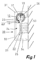
- Figure 1 shows a section through an assembly device, after which all the elements are assembled and the furniture is mounted on the wall 50. In the illustration you have to imagine the wall on the right. The cut is perpendicular to the wall.
- the core of the invention that is the carrier element 10, runs parallel to the wall and horizontally.
- the carrier element 10 is tubular, has an essentially circular cross section and has a cavity 11 on the inside.
- the carrier element 10 is slotted at the bottom; the slit 12 is filled in the illustration by another element to be described later, but recognizable.
- the cross section is essentially of the same shape over the entire length of the support element, it can optionally be closed at the tube ends of the support element 10 by plugs or in some other way.
- a stabilizing rib part 13 protrudes into the cavity 11 exactly opposite the slot 12, that is to say from above.
- the entire tubular or rod-like support element 10 can initially be aligned freely in front of this wall and tried out at what height and position it is to be mounted. If this position is approximately fixed, a further element of the invention is used, namely the wall fastening element 20.
- the wall fastening element 20 is arranged to be longitudinally displaceable in the carrier element 10. In the embodiment shown, it consists of a small square plate 21, the diagonal of which is approximately as large or slightly larger than the diameter of the carrier element 10.
- the material of the plate 21, like that of the carrier element 10, is stainless steel or another stable metal or other material.
- the top edge of the plate 21 projects through the slot 12 into the cavity 11 inside the carrier element 10.
- the plate 21 is connected to a piece of pipe 22.
- This piece of pipe is approximately as long as the plate 21 extends in the longitudinal direction, also has a circular cross section and its outer diameter is approximately adapted to the inner diameter of the carrier element 10.
- the plate 21 and the tubular piece 22 together form a rider element 23.
- the rider element 23 is held captively in the carrier element 10.
- the rider element 23 is thereby mounted in the carrier element 10 so as to be longitudinally displaceable, but at the same time holds it firmly on the wall 50.
- the tube piece 22 is interrupted in its upper part so that the stabilizing rib part 13 of the support element 10 can protrude.
- This interruption 26 of the upper half of the pipe section 22 is so narrow, however, that the inside of the carrier element 10 can still be supported on the outside of the pipe section 22 when force is exerted from above.
- this tab element 23 can now be pushed back and forth and a location in the wall area can be selected at which the tab element 23 would be optimally placed, for example for reasons of stability or because there are no lines in the wall.
- a fastening device 24, in particular a screw, projecting through it and held in it is anchored in the wall 50.
- this screw is only indicated by its screw axis for the sake of simplicity; it would protrude further to the right than shown in order to be anchored in the wall, for example in a dowel to be provided there (also not shown).
- the fastening device 24 also projects through a spacer element 25, which defines the distance of the plate 21 from the wall, so that the carrier element 10 stands freely above the plate 21 in space and does not directly adjoin the wall.
- a further wall fastening element of this type can likewise be displaced longitudinally in the carrier element 10 until it is arranged at a suitable point. It is then attached there.
- the support element is thus fixed in its height position and its distance in front of the wall.
- the carrier element 10 itself could now be pushed back and forth if this is intended with regard to its extension.
- a third or further wall fastening elements 20 could be provided. If an element of the carrier element 10 is open at the end, these wall fastening elements can each be pushed in until assembly.
- a hanging element 30 is provided for this purpose.
- the hanging element 30 is approximately C-shaped in cross section.
- the side of the hanging element 30 facing the wall is essentially open.
- the top has a section 31 which engages over the carrier element 10 from above and is adapted in this area so that it rests positively on the carrier element 10.
- the area 32 facing away from the wall 50 is perpendicular to the surface and merges downwards into a horizontally extending section 34.
- the entire construction of the hanging element 30 is also uniform over a certain length.
- the hanging element 30 is an integral part of a piece of furniture that has to be imagined in FIG. 1 on the left. It is therefore a part of a rear wall of a piece of furniture or the entire rear wall of a piece of furniture if it is a flat piece of furniture approximately at the height of the support element, such as a washstand.
- the hanging element 30 can also be part of a profile part of a piece of furniture and lasered out of it or cut out by another method.
- FIGS. 2 and 3 show the carrier element 10 in a perspective view. Above all in FIG. 3, the tubular shape of the carrier element 10 with its essentially circular cross section, the inner cavity 11, the elongated slot 12 on the underside of the tubular shape and the stabilizing rib 13, which also protrudes from above, can be clearly seen.
- the slot runs the wall fastening element 20, of which only the plate 21 and - facing away from the viewer - the spacer element 25 extending towards the rear of the wall can be seen in FIG. 3.
- FIG. 2 in a perspective representation from another direction - as it were seen from the wall - the spacer element 25 turns towards the viewer and its structure can be seen more clearly.
- a bore 27 is provided for the screw, which is also omitted here, and which anchors the wall fastening element 20 to the wall.
- ribs 28 are provided in a line alignment, which form an internal stiffening of the spacer element.
- the wall fastening element 20 with the plate 21 can be displaced relative to the carrier element 10 parallel to its axis.
- FIG. 4 illustrates the overall structure in a perspective view corresponding to FIG. 1.
- support element 10 and plate 21 with spacer element 25 in particular the hanging element 30 already suspended here on tubular support element 10 can be seen.
- the pieces of furniture, wash basin and other furnishing elements connected to the hanging element 30, which are fastened to the wall with the inventive concept, are omitted here for the sake of clarity. They would now be in front of the carrier element 10 for the viewer in FIG.
- the nose-shaped part 35 of the section 31 of the hanging element 30 which reaches behind the carrier element is in particular only 5-6 mm deep and is attached to the wall (not shown).
- the rear wall of the piece of furniture etc. is then aligned with this.
- the hanging element is integrated in the piece of furniture, etc., which means that the entire rear wall can be flush with the wall.
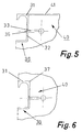
- FIGS. 5 and 6 show the hanging element 30 separately for clarification. It is shown here as a mirror image of FIG. 1, which means that the wall would be on the left side after assembly, and the piece of furniture on the right.
- the exemplary embodiment shown in FIG. 5 shows a surface area 41 of the piece of furniture 40 which ends flush with the section 31 and forms a common horizontal plane. This could, for example, be a washstand. This can be removed from the carrier element or hung on this carrier element again at another location.
- Area 32 of the hanging element 30 is provided with an opening 36 and a fastening device 33 with which the hanging element 30 becomes an integral part of the piece of furniture 40.
- FIG. 6 shows a slightly modified embodiment in which the piece of furniture does not end flush at the top with the upper flat edge of the hanging element 30, but in which the hanging element is integrated in the piece of furniture 40 both above and below.
- This can be a continuous closet, for example; Such a thing can also be exchangeably mounted on a wall with the same support element.
- This embodiment of the hanging element 30 differs by the rounded edges 37 on the section 31, which facilitate installation in a corresponding piece of furniture.
- the hanging element which preferably has the same length as the width of the piece of furniture, at different heights within the respective pieces of furniture, Different heights of furniture can be created and attached to one and the same support element (ie a fixed height of the support element above the floor).
- FIG. 7 The appearance of a fully assembled bathroom device is shown in FIG. 7 purely by way of example.
- Several pieces of furniture 40 and other objects are lined up on this carrier element; they could be moved in front of the wall 50, but they are kept stable by their own weight. Moving is possible by lifting it slightly.
- a complete removal from the device and a removal from the wall in the case of an intended new furnishing can take place easily and by the owner himself, without any greater specialist knowledge, if the piece of furniture in question is simply raised so far that the hanging element moves up and down from the carrier element 10 let down in front.
- other or additional pieces of furniture 40 can be placed between the existing ones without any problems can be added by hanging the C-shaped hanging elements in the carrier element 10.
- clamping elements in particular screws, can be provided in the upper and lower areas 60, 61 in the rear wall of the furniture or objects. By tightening the screws, the rear wall can then be braced against the wall 50, the connection between the hanging element and the support element being a rigid crease line.
Landscapes
- Health & Medical Sciences (AREA)
- Public Health (AREA)
- Supports Or Holders For Household Use (AREA)
Applications Claiming Priority (4)
| Application Number | Priority Date | Filing Date | Title |
|---|---|---|---|
| DE19619025 | 1996-05-10 | ||
| DE19619025 | 1996-05-10 | ||
| DE19628210A DE19628210A1 (de) | 1996-05-10 | 1996-07-12 | Montageeinrichtung und Verfahren zur Montage von Möbeln und Waschplatzelementen an einer Wand |
| DE19628210 | 1996-07-12 |
Publications (2)
| Publication Number | Publication Date |
|---|---|
| EP0806164A1 true EP0806164A1 (fr) | 1997-11-12 |
| EP0806164B1 EP0806164B1 (fr) | 2000-08-16 |
Family
ID=26025610
Family Applications (1)
| Application Number | Title | Priority Date | Filing Date |
|---|---|---|---|
| EP19970107441 Expired - Lifetime EP0806164B1 (fr) | 1996-05-10 | 1997-05-06 | Dispositif et procédé pour la fixation d'ameublement et des meubles de toilette à une paroie |
Country Status (1)
| Country | Link |
|---|---|
| EP (1) | EP0806164B1 (fr) |
Cited By (1)
| Publication number | Priority date | Publication date | Assignee | Title |
|---|---|---|---|---|
| US9345327B2 (en) | 2014-03-18 | 2016-05-24 | Btps, Llc | Wall-mount vanity bracket |
Families Citing this family (1)
| Publication number | Priority date | Publication date | Assignee | Title |
|---|---|---|---|---|
| DE102007010916A1 (de) | 2007-03-05 | 2008-09-11 | Alape Gmbh | Montageeinrichtung für die Montage von Waschplatzelementen an einer Wand |
Citations (3)
| Publication number | Priority date | Publication date | Assignee | Title |
|---|---|---|---|---|
| US5050832A (en) * | 1990-05-18 | 1991-09-24 | Lee/Rowan Company | Modular storage unit mounting system |
| DE4114378A1 (de) * | 1991-05-02 | 1992-11-05 | Bulthaup Gmbh & Co | Schrankaufhaengevorrichtung |
| US5392934A (en) * | 1993-05-14 | 1995-02-28 | Fox; Larry G. | Apparatus and method for adjustably supporting furnishings on a wall surface |
-
1997
- 1997-05-06 EP EP19970107441 patent/EP0806164B1/fr not_active Expired - Lifetime
Patent Citations (3)
| Publication number | Priority date | Publication date | Assignee | Title |
|---|---|---|---|---|
| US5050832A (en) * | 1990-05-18 | 1991-09-24 | Lee/Rowan Company | Modular storage unit mounting system |
| DE4114378A1 (de) * | 1991-05-02 | 1992-11-05 | Bulthaup Gmbh & Co | Schrankaufhaengevorrichtung |
| US5392934A (en) * | 1993-05-14 | 1995-02-28 | Fox; Larry G. | Apparatus and method for adjustably supporting furnishings on a wall surface |
Cited By (1)
| Publication number | Priority date | Publication date | Assignee | Title |
|---|---|---|---|---|
| US9345327B2 (en) | 2014-03-18 | 2016-05-24 | Btps, Llc | Wall-mount vanity bracket |
Also Published As
| Publication number | Publication date |
|---|---|
| EP0806164B1 (fr) | 2000-08-16 |
Similar Documents
| Publication | Publication Date | Title |
|---|---|---|
| EP2333169B1 (fr) | Dispositif sanitaire et fixation destinée à fixer un dispositif sanitaire | |
| DE202015009052U1 (de) | Montagevorrichtung | |
| EP0806164B1 (fr) | Dispositif et procédé pour la fixation d'ameublement et des meubles de toilette à une paroie | |
| EP1231328B1 (fr) | Cadre de montage pour appareils sanitaires | |
| DE3041144A1 (de) | Beschlag zum aufhaengen eines schrankes o.dgl. | |
| EP1335077A1 (fr) | Dispositif de fixation d'objets sanitaires suspendus | |
| AT502463B1 (de) | Höhenverstellbare sitzvorrichtung | |
| DE29611951U1 (de) | Traggestellrahmen | |
| DE19628210A1 (de) | Montageeinrichtung und Verfahren zur Montage von Möbeln und Waschplatzelementen an einer Wand | |
| DE19736341C2 (de) | Befestigungsvorrichtung | |
| EP3586704B1 (fr) | Séparation de douche pourvue d'une porte de douche pivotante | |
| DE7626246U1 (de) | Einbau-traggeruest fuer hohlkoerperwaende zur befestigung von wandhaengenden sanitaereinrichtungen | |
| EP2124677B1 (fr) | Système d'étagère | |
| AT501147A4 (de) | Tragrahmen | |
| EP1428941A2 (fr) | Dispositif de fixation d'un article sanitaire | |
| DE4219852A1 (de) | Vorrichtung für ein schraubenlos zusammenfügbares Regalsystem | |
| DE29803307U1 (de) | Installationsrahmen für die Vorwandmontage | |
| DE29513690U1 (de) | Befestigungsvorrichtung für die Raumausstattung | |
| DE9304857U1 (de) | Verkleidung für Sanitärbecken | |
| DE19851450A1 (de) | Installationselement | |
| AT414207B (de) | Aufhängevorrichtung für einen duschvorhang | |
| AT517845B1 (de) | Zierhalterungsvorrichtung | |
| DE29817039U1 (de) | Befestigungssystem für Wandmöbel | |
| EP2308357B1 (fr) | Baguette de garde-robe | |
| CH719225B1 (de) | Montagevorrichtung für die Befestigung von mindestens einem Sanitärartikel |
Legal Events
| Date | Code | Title | Description |
|---|---|---|---|
| PUAI | Public reference made under article 153(3) epc to a published international application that has entered the european phase |
Free format text: ORIGINAL CODE: 0009012 |
|
| AK | Designated contracting states |
Kind code of ref document: A1 Designated state(s): BE CH DE LI NL |
|
| 17P | Request for examination filed |
Effective date: 19971119 |
|
| 17Q | First examination report despatched |
Effective date: 19980415 |
|
| GRAG | Despatch of communication of intention to grant |
Free format text: ORIGINAL CODE: EPIDOS AGRA |
|
| GRAG | Despatch of communication of intention to grant |
Free format text: ORIGINAL CODE: EPIDOS AGRA |
|
| GRAH | Despatch of communication of intention to grant a patent |
Free format text: ORIGINAL CODE: EPIDOS IGRA |
|
| GRAH | Despatch of communication of intention to grant a patent |
Free format text: ORIGINAL CODE: EPIDOS IGRA |
|
| GRAA | (expected) grant |
Free format text: ORIGINAL CODE: 0009210 |
|
| AK | Designated contracting states |
Kind code of ref document: B1 Designated state(s): BE CH DE LI NL |
|
| PG25 | Lapsed in a contracting state [announced via postgrant information from national office to epo] |
Ref country code: NL Free format text: LAPSE BECAUSE OF FAILURE TO SUBMIT A TRANSLATION OF THE DESCRIPTION OR TO PAY THE FEE WITHIN THE PRESCRIBED TIME-LIMIT Effective date: 20000816 |
|
| REG | Reference to a national code |
Ref country code: CH Ref legal event code: EP |
|
| REF | Corresponds to: |
Ref document number: 59702178 Country of ref document: DE Date of ref document: 20000921 |
|
| EN | Fr: translation not filed | ||
| PG25 | Lapsed in a contracting state [announced via postgrant information from national office to epo] |
Ref country code: BE Free format text: LAPSE BECAUSE OF NON-PAYMENT OF DUE FEES Effective date: 20010531 |
|
| PG25 | Lapsed in a contracting state [announced via postgrant information from national office to epo] |
Ref country code: LI Free format text: LAPSE BECAUSE OF NON-PAYMENT OF DUE FEES Effective date: 20010605 Ref country code: CH Free format text: LAPSE BECAUSE OF NON-PAYMENT OF DUE FEES Effective date: 20010605 |
|
| PLBE | No opposition filed within time limit |
Free format text: ORIGINAL CODE: 0009261 |
|
| STAA | Information on the status of an ep patent application or granted ep patent |
Free format text: STATUS: NO OPPOSITION FILED WITHIN TIME LIMIT |
|
| 26N | No opposition filed | ||
| BERE | Be: lapsed |
Owner name: ALAPE ADOLF LAMPRECHT K.G. Effective date: 20010531 |
|
| REG | Reference to a national code |
Ref country code: CH Ref legal event code: PL |
|
| PGFP | Annual fee paid to national office [announced via postgrant information from national office to epo] |
Ref country code: DE Payment date: 20040521 Year of fee payment: 8 |
|
| PG25 | Lapsed in a contracting state [announced via postgrant information from national office to epo] |
Ref country code: DE Free format text: LAPSE BECAUSE OF NON-PAYMENT OF DUE FEES Effective date: 20051201 |