EP0806185A1 - Fixateur externe - Google Patents
Fixateur externe Download PDFInfo
- Publication number
- EP0806185A1 EP0806185A1 EP97810280A EP97810280A EP0806185A1 EP 0806185 A1 EP0806185 A1 EP 0806185A1 EP 97810280 A EP97810280 A EP 97810280A EP 97810280 A EP97810280 A EP 97810280A EP 0806185 A1 EP0806185 A1 EP 0806185A1
- Authority
- EP
- European Patent Office
- Prior art keywords
- bar
- plugs
- bone
- jaws
- vice
- Prior art date
- Legal status (The legal status is an assumption and is not a legal conclusion. Google has not performed a legal analysis and makes no representation as to the accuracy of the status listed.)
- Granted
Links
Images
Classifications
-
- A—HUMAN NECESSITIES
- A61—MEDICAL OR VETERINARY SCIENCE; HYGIENE
- A61B—DIAGNOSIS; SURGERY; IDENTIFICATION
- A61B17/00—Surgical instruments, devices or methods
- A61B17/56—Surgical instruments or methods for treatment of bones or joints; Devices specially adapted therefor
- A61B17/58—Surgical instruments or methods for treatment of bones or joints; Devices specially adapted therefor for osteosynthesis, e.g. bone plates, screws or setting implements
- A61B17/60—Surgical instruments or methods for treatment of bones or joints; Devices specially adapted therefor for osteosynthesis, e.g. bone plates, screws or setting implements for external osteosynthesis, e.g. distractors, contractors
- A61B17/64—Devices extending alongside the bones to be positioned
- A61B17/6466—Devices extending alongside the bones to be positioned with pin-clamps movable along a solid connecting rod
Definitions
- the present invention is in the field of orthopedics and relates more particularly to an external fixator intended for the consolidation of a long bone, fractured towards its end.
- a fixator comprising a single stiffening bar and not a series of bars forming a stiffening frame.
- pairs of at least two bone plugs are inserted on either side of the fracture and are indirectly fixed to the ends of a stiffening bar.
- T so-called "T" arrangement, some of the cards being inserted in the epiphysis in a plane perpendicular to the bone, the others being inserted in the central part of the bone, in a plane containing the fractured bone.
- Each group of plugs is held in a vice that can be oriented relative to the stiffening bar by means of a joint or a ball joint.
- one of the jaws of each vice comprises a cylindrical bar intended to cooperate with a joint.
- the invention also extends to a method of positioning the fixator according to the invention and of positioning the bone fragments by means of the combination of rotational movements.
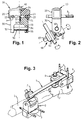
- FIG. 1 represents the vice according to the invention, seen from the front in the left part of the drawing and in section in the right part.
- Figure 3 is a perspective view of the set of the fixator according to the invention.
- the vice 10 shown in Figure 1 is conventionally constituted by an upper jaw 20 and a lower jaw 30 connected by a central clamping screw 40. These jaws 20 and 30 have a series of parallel grooves 21 and 31 for the plugs bone 3.
- the upper jaw 20 further comprises two wings 22 and 23 for relative positioning of the jaws and a central passage 24 in which the clamping screw 40 passes freely.
- the lower jaw 30 has a general shape of "U" (upside down in the drawing), whose legs 32 and 33 are intended to receive a bar 50 whose ends are inserted in a passage 34 formed in each leg, and fixed by means of a pin 35 intended to prevent any rotation of the bar.
- the lower jaw 30 also includes a central passage 36 intended to cooperate with the screw 40.
- a threaded metal sleeve 37 is interposed between the passage 36 and the screw 40.
- the jaws 20 and 30 forming the vice 10 for clamping the plugs 3, the lower jaw 30 having the bar 50 intended for the fixing of a joint 60.
- This comprises a first pair of jaws 61 clamped on a spreader bar and a second pair of jaws 62 clamped on the bar 50, these pairs of jaws can be oriented relative to a central axis constituted by the clamping screw 63 which constitutes the axis jaw rotation. Provision can be made to separate the pairs of jaws 61 and 62 by a helical spring 64, intended to hold the components in place before the screw 63 is fully tightened, as detailed in the European patent application No. 0.700.664 already cited.
- the sheets 3 are in a horizontal plane while the sheets 4 are in a vertical plane. It will be noted that the axis of the articulation 8 is substantially parallel to the plugs 4, while the axis of the articulation 7 is 45 ° from the plane containing the plugs 3.
- the method of fitting the fixator described so far is to insert pairs of plugs into the bone fragments on either side of the fracture, to tighten the plugs in the vices, to mount the joints on the vices and on a stiffening bar, before proceeding to the final adjustment of the position of the bone fragments thanks to the combination of the rotational movements of the joints or in other words the positioning of the stiffening bar relative to the sheets.
- clamps and even a stiffening bar made of composite materials transparent to X-rays will advantageously be used to easily verify the relative positioning of the bone fragments during the positioning of the fixative.
- reinforced plastics will be used, preferably based on carbon fibers.
- the bars 50 and the spacer bar 9 have the same diameter, which allows greater freedom in the positioning of the components and to limit as much as possible the size and the protruding parts of the jaws and the joints, all allowing easy access to the clamping parts.
Landscapes
- Health & Medical Sciences (AREA)
- Orthopedic Medicine & Surgery (AREA)
- Life Sciences & Earth Sciences (AREA)
- Surgery (AREA)
- Biomedical Technology (AREA)
- Engineering & Computer Science (AREA)
- Nuclear Medicine, Radiotherapy & Molecular Imaging (AREA)
- Heart & Thoracic Surgery (AREA)
- Medical Informatics (AREA)
- Molecular Biology (AREA)
- Animal Behavior & Ethology (AREA)
- General Health & Medical Sciences (AREA)
- Public Health (AREA)
- Veterinary Medicine (AREA)
- Surgical Instruments (AREA)
Abstract
Description
- La présente invention est du domaine de l'orthopédie et concerne plus particulièrement un fixateur externe destiné à la consolidation d'un os long, fracturé vers son extrémité.
- Depuis de nombreuses années, on a développé des fixateurs externes dont les composants sont mis en place après que les fiches aient été insérées dans la position optimale par rapport au fragment osseux à maintenir et au tissu l'entourant. Des articulations assurent la liaison entre les fiches et la ou les barre(s) de rigidification, pour assurer leur orientation relative. La déposante a plus particulièrement développé à cette fin l'articulation décrite dans la demande de brevet européen No 0.700.664 qui permet d'orienter soit une fiche et une barre, soit deux barres entre elles. Cette articulation comporte plusieurs paires de mâchoires formant des rainures positionnées et agencées de manière à présenter une ouverture extérieure permettant le clipsage de la pièce cylindrique par pression de cette dernière à l'encontre des moyens élastiques qui pressent les faces adjacentes des mâchoires l'une contre l'autre, pour maintenir l'articulation sur les pièces cylindriques avant le blocage de l'articulation.
- Dans certains cas, on est amené à utiliser un fixateur comportant une barre de rigidification unique et non pas une série de barres formant un cadre de rigidification. Pour ce type de fixateur, des paires d'au moins deux fiches osseuses sont insérées de part et d'autre de la fracture et sont indirectement fixées aux extrémités d'une barre de rigidification. Lorsqu'un os long est fracturé au voisinage d'une articulation, il est préférable d'insérer les fiches dans une disposition dite en "T", certaines des fiches étant insérées dans l'épiphyse dans un plan perpendiculaire à l'os, les autres étant insérées dans la partie centrale de l'os, dans un plan contenant l'os fracturé. Chaque groupe de fiches est maintenu dans un étau que l'on peut orienter par rapport à la barre de rigidification grâce à une articulation ou une rotule.
- La présente invention vise à simplifier ce type de montage et à diminuer l'encombrement et le poids de l'ensemble, plus particulièrement étudié pour les os longs, tels le radius, fracturés aux environs de leur extrémité. Elle a pour objet un fixateur comportant au moins :
- deux groupes de fiches insérées respectivement de part et d'autre de la fracture,
- deux étaux de fixation des fiches,
- deux articulations assurant l'orientation des étaux par rapport à une barre de rigidification.
- Elle est caractérisée par le fait que l'une des mâchoires de chaque étau comporte une barrette cylindrique destinée à coopérer avec une articulation.
- L'invention s'étend également à un procédé de mise en place du fixateur selon l'invention et de positionnement des fragments osseux grâce à la combinaison de mouvements de rotation.
- Le dessin annexé représente à titre d'exemple non limitatif une forme d'exécution de l'objet de la présente invention.
- La figure 1 représente l'étau selon l'invention, vu de face dans la partie gauche du dessin et en coupe dans la partie droite.
- La figure 2 représente l'étau de la figure 1 vu latéralement et représenté monté sur une articulation du type de celle décrite dans la demande de brevet européen No 0.700.664 au nom de la déposante.
- La figure 3 est une vue en perspective de l'ensemble du fixateur selon l'invention.
- L'étau 10 représenté à la figure 1 est constitué de manière conventionnelle par une mâchoire supérieure 20 et une mâchoire inférieure 30 reliées par une vis centrale de serrage 40. Ces mâchoires 20 et 30 comportent des séries de rainures parallèles 21 et 31 pour les fiches osseuses 3.
- La mâchoire supérieure 20 comporte en outre deux ailes 22 et 23 de positionnement relatif des mâchoires et un passage central 24 dans lequel la vis de serrage 40 passe librement.
- La mâchoire inférieure 30 a une forme générale de "U" (à l'envers au dessin), dont les jambages 32 et 33 sont destinés à recevoir une barrette 50 dont les extrémités sont insérées dans un passage 34 pratiqué dans chaque jambage, et fixées au moyen d'une goupille 35 destinée à empêcher toute rotation de la barrette. La mâchoire inférieure 30 comporte également un passage central 36 destiné à coopérer avec la vis 40. De préférence un manchon métallique fileté 37 est intercalé entre le passage 36 et la vis 40. Par construction la barrette 50 est parallèle au plan contenant les fiches et, comme visible au dessin, elle est perpendiculaire à l'axe des fiches osseuses.
- Dans la vue de côté de la figure 2 on retrouve les mâchoires 20 et 30 formant l'étau 10 de serrage de fiches 3, la mâchoire inférieure 30 présentant la barrette 50 destinée à la fixation d'une articulation 60. Celle-ci comporte une première paire de mâchoires 61 serrées sur une barre d'écartement et une seconde paire de mâchoires 62 serrées sur la barrette 50, ces paires de mâchoires pouvant être orientées par rapport à un axe central constitué par la vis de serrage 63 qui constitue l'axe de rotation des mâchoires. On peut prévoir de séparer les paires de mâchoires 61 et 62 par un ressort hélicoïdal 64, destiné à tenir les composants en place avant que la vis 63 soit totalement serrée, comme détaillé dans la demande de brevet européen No 0.700.664 déjà citée.
- Dans la vue générale de la figure 3 on a représenté un os long 1 fracturé relativement près de l'extrémité distale 2 du radius, région dans laquelle ont lieu plus de 20% des fractures des membres. Chaque fragment osseux 1 ou 2 reçoit respectivement au moins deux fiches 3 ou 4, disposées de préférence en "T". Ces fiches sont serrées dans deux étaux 5 et 6 coopérant avec des articulations 7 et 8 entre lesquelles est disposée une barre 9 de rigidification. Le médecin pourra réduire la fracture et remettre les fragments osseux 1 et 2 dans leur position optimale grâce à la combinaison des mouvements de rotation :
- des articulations 7 et 8 par rapport à l'axe de la barre 9,
- des paires de mâchoires de chaque articulation 7 ou 8 sur leur axe de serrage 63,
- des articulations 7 et 8 par rapport à la barrette de chaque étau 5 ou 6.
- Dans la représentation de la figure 3 les fiches 3 sont dans un plan horizontal tandis que les fiches 4 sont dans un plan vertical. On notera que l'axe de l'articulation 8 est sensiblement parallèle aux fiches 4, tandis que l'axe de l'articulation 7 est à 45° du plan contenant les fiches 3.
- Dans les fractures du poignet, on a remarqué que l'on a avantage à disposer de préférence les fiches 3 dans un plan à 45° de l'horizontale, l'axe de l'articulation 7 étant sensiblement aligné sur l'axe central de serrage de l'étau 5. Selon la région d'utilisation du fixateur selon l'invention, on peut prévoir de disposer les deux groupes de fiches dans des plans sensiblement parallèles, et non dans la disposition en "T" telle que décrite précédemment, sans sortir du cadre de la présente invention.
- Le procédé de mise en place du fixateur décrit jusqu'ici est consiste à insérer des paires de fiches dans les fragments osseux de part et d'autre de la fracture, à serrer les fiches dans les étaux, à monter les articulations sur les étaux et sur une barre de rigidification, avant de procéder au réglage final de la position des fragments osseux grâce à la combinaison des mouvements de rotation des articulations ou en d'autres termes le positionnement de la barre de rigidification par rapport aux fiches.
- Il est à noter encore que l'on utilisera avantageusement des étaux et même une barre de rigidification en matériaux composites transparents aux rayons X pour vérifier aisément le positionnement relatif des fragments osseux lors de la mise en place du fixateur. Par exemple on utilisera des matières plastiques renforcées, de préférence à base de fibres de carbone.
- De préférence, les barrettes 50 et la barre d'écartement 9 ont le même diamètre, ce qui permet une plus grande liberté dans le positionnement des composants et de limiter au maximum l'encombrement et les parties en saillie des mâchoires et des articulations, tout en autorisant un accès facile aux pièces de serrage.
Claims (7)
- Fixateur externe comportant au moins :• deux groupes de fiches (3,4) insérées respectivement de part et d'autre de la fracture,• deux étaux (5,6; 10) de fixation des fiches,• deux articulations (7,8; 60) assurant l'orientation des étaux par rapport à une barre de rigidification (9),caractérisé par le fait que l'une des mâchoires de chaque étau comporte une barrette cylindrique (50) destinée à coopérer avec une articulation.
- Fixateur selon la revendication 1, caractérisé en ce que ladite barrette (50) est parallèle au plan des fiches (3) et perpendiculaire par rapport à l'axe de celles-ci.
- Fixateur selon la revendication 2, caractérisé par le fait que chaque étau comporte une mâchoire (30) en forme de U dont les jambages (32,33) comportent deux ouvertures (34) vis-à-vis, dans lesquelles sont insérées les extrémités de la barrette (50).
- Fixateur selon la revendication 3, caractérisé par le fait que ledit jambage (32,33) comporte en outre un passage pour un moyen de blocage (35) de la barrette (50) en rotation.
- Fixateur selon la revendication 1, caractérisé par le fait que les mâchoires 20 et 30 de l'étau sont en matériaux plastiques renforcés.
- Procédé de mise en place du fixateur de la revendication 1, caractérisé par l'insertion des paires de fiches (3,4) dans les fragments osseux (1,2) de part et d'autre de la fracture, par le serrage des fiches dans les étaux (5,6), par le montage des articulations (7,8) sur les étaux et sur une barre de rigidification (9), avant de procéder au réglage final de la position des fragments osseux par le positionnement de la barre de rigidification par rapport aux fiches.
- Procédé de mise en place selon la revendication 6, caractérisé par une disposition des fiches en "T", les fiches (4) étant insérées dans un plan perpendiculaire à un os long, les fiches (3) étant insérées dans un plan passant sensiblement par l'axe de l'os fracturé.
Applications Claiming Priority (4)
| Application Number | Priority Date | Filing Date | Title |
|---|---|---|---|
| CH1206/96 | 1996-05-10 | ||
| CH120696 | 1996-05-10 | ||
| CH01206/96A CH691568A5 (fr) | 1996-05-10 | 1996-05-10 | Fixateur externe. |
| US08/843,420 US5891144A (en) | 1996-05-10 | 1997-04-15 | External fixator |
Publications (2)
| Publication Number | Publication Date |
|---|---|
| EP0806185A1 true EP0806185A1 (fr) | 1997-11-12 |
| EP0806185B1 EP0806185B1 (fr) | 2002-11-27 |
Family
ID=25686989
Family Applications (1)
| Application Number | Title | Priority Date | Filing Date |
|---|---|---|---|
| EP97810280A Expired - Lifetime EP0806185B1 (fr) | 1996-05-10 | 1997-05-05 | Fixateur externe |
Country Status (4)
| Country | Link |
|---|---|
| US (1) | US5891144A (fr) |
| EP (1) | EP0806185B1 (fr) |
| JP (1) | JP3085919B2 (fr) |
| CA (1) | CA2204449C (fr) |
Cited By (3)
| Publication number | Priority date | Publication date | Assignee | Title |
|---|---|---|---|---|
| US6409729B1 (en) | 1998-05-19 | 2002-06-25 | Synthes (Usa) | Clamp assembly for an external fixation system |
| EP1839605A1 (fr) | 2006-03-31 | 2007-10-03 | Stryker Trauma SA | Elément de fixateur externe à surface rugueuse traitée par érosion |
| US10864017B2 (en) | 2016-01-15 | 2020-12-15 | Gexfix Sa | Orthopaedic attachment device |
Families Citing this family (65)
| Publication number | Priority date | Publication date | Assignee | Title |
|---|---|---|---|---|
| US6423069B1 (en) * | 1999-03-23 | 2002-07-23 | Synthes (Usa) | Orthopedic system having detachable bone anchors |
| JP2001037767A (ja) * | 1999-08-02 | 2001-02-13 | Kyowa Tokei Kogyo Kk | 骨調整具 |
| US6277119B1 (en) | 1999-10-21 | 2001-08-21 | Electro-Biology, Inc. | External fixation system |
| US6616664B2 (en) | 1999-10-21 | 2003-09-09 | Ebi L.P. | Clamp assembly for an external fixation system |
| US6613049B2 (en) * | 2000-02-02 | 2003-09-02 | Robert A. Winquist | Adjustable bone stabilizing frame system |
| WO2001091647A1 (fr) * | 2000-05-31 | 2001-12-06 | Stratec Medical Ag | Dispositif pour le positionnement d'un instrument chirurgical |
| US6565564B2 (en) * | 2000-12-14 | 2003-05-20 | Synthes U.S.A. | Multi-pin clamp and rod attachment |
| US6482206B2 (en) | 2001-02-22 | 2002-11-19 | Biomet, Inc. | Method and apparatus for external fixation of bones |
| US6872210B2 (en) * | 2001-02-23 | 2005-03-29 | James P. Hearn | Sternum fixation device |
| US7261713B2 (en) * | 2001-10-09 | 2007-08-28 | Synthes (Usa) | Adjustable fixator |
| US6709433B1 (en) | 2001-12-20 | 2004-03-23 | Biomet, Inc. | Bridging/non-bridging external bone fixator |
| US7048735B2 (en) | 2002-02-04 | 2006-05-23 | Smith & Nephew | External fixation system |
| US7004943B2 (en) * | 2002-02-04 | 2006-02-28 | Smith & Nephew, Inc. | Devices, systems, and methods for placing and positioning fixation elements in external fixation systems |
| US7758582B2 (en) * | 2002-06-14 | 2010-07-20 | Smith & Nephew, Inc. | Device and methods for placing external fixation elements |
| US7282052B2 (en) * | 2002-09-17 | 2007-10-16 | Ebi, L.P. | Unilateral fixator |
| CA2505744C (fr) * | 2002-11-14 | 2012-05-29 | Visionmed, Llc | Procede d'utilisation d'un fixateur |
| AU2003295521A1 (en) * | 2002-11-15 | 2004-06-15 | Amei Technologies Inc. | Apparatus and method for maintaining bones in a healing position |
| US7608074B2 (en) * | 2003-01-10 | 2009-10-27 | Smith & Nephew, Inc. | External fixation apparatus and method |
| EP1522266A1 (fr) * | 2003-10-06 | 2005-04-13 | Stryker Trauma SA | Elements de fixation externe |
| CA2563547C (fr) * | 2004-04-19 | 2015-01-27 | Synthes Gmbh | Element elastique realise dans un materiau permeable aux rayons x et destine a un dispositif medical |
| EP1627609B1 (fr) * | 2004-08-20 | 2007-10-17 | Stryker Trauma SA | Elément de serrage pour accrocher ensemble plusieurs tiges |
| US20060235383A1 (en) * | 2005-03-07 | 2006-10-19 | Shane Hollawell | External fixator |
| US8758343B2 (en) | 2005-04-27 | 2014-06-24 | DePuy Synthes Products, LLC | Bone fixation apparatus |
| GB2427141B (en) * | 2005-06-13 | 2010-12-22 | Intelligent Orthopaedics Ltd | Fixator |
| US8523858B2 (en) | 2005-06-21 | 2013-09-03 | DePuy Synthes Products, LLC | Adjustable fixation clamp and method |
| US7708736B2 (en) | 2006-02-22 | 2010-05-04 | Extraortho, Inc. | Articulation apparatus for external fixation device |
| ES2638425T3 (es) * | 2006-05-29 | 2017-10-20 | Stryker European Holdings I, Llc | Elemento de sujecion y pieza de insercion para el mismo |
| ES2471948T3 (es) * | 2006-10-13 | 2014-06-27 | Stryker Trauma Sa | Prevención de reutilización de un dispositivo m�dico |
| US8277448B2 (en) * | 2007-03-07 | 2012-10-02 | Wright Medical Technology, Inc. | External fixation |
| WO2009042836A1 (fr) | 2007-09-27 | 2009-04-02 | Qfx Technologies, Incorporated | Procédé et appareil de clampage pour fixation externe et stabilisation |
| AU2009276320B2 (en) * | 2008-08-01 | 2014-08-21 | Skeletal Holdings, Llc | Internal joint stabilizer device, system, and method of use |
| US10327817B2 (en) | 2008-08-01 | 2019-06-25 | Skeletal Dynamics Llc | Internal joint stabilizer device, system and method of use |
| EP2294994B1 (fr) * | 2009-09-11 | 2018-04-04 | Stryker European Holdings I, LLC | Composant de fixation externe |
| WO2012003455A1 (fr) | 2010-07-01 | 2012-01-05 | Extraortho, Inc. | Collier de fixation externe à verrouillage multiple |
| EP2438869B1 (fr) | 2010-10-07 | 2015-04-29 | Stryker Trauma SA | Élément de couplage pour fixateur externe |
| EP3388007A3 (fr) | 2010-10-12 | 2019-02-20 | Zimmer, Inc. | Agencement de pince de fixation externe à verrou unique |
| EP2627273B1 (fr) | 2010-10-12 | 2017-03-01 | Zimmer, Inc. | Clamp chirurgical de fixation externe comportant un pivot |
| WO2012061692A1 (fr) | 2010-11-04 | 2012-05-10 | Extraortho, Inc. | Ensemble de serrage comprenant des pièces de liaison |
| WO2012078897A1 (fr) | 2010-12-09 | 2012-06-14 | Extraortho, Inc. | Verrou rotatif pour clamps de fixation externe |
| WO2012078893A1 (fr) | 2010-12-09 | 2012-06-14 | Extraortho, Inc. | Mâchoire actionnée par came pour pinces de fixation externes |
| ES2541207T3 (es) | 2010-12-14 | 2015-07-16 | Stryker Trauma Sa | Pinza de fijación con rueda selectora |
| EP2465453B1 (fr) | 2010-12-14 | 2015-04-08 | Stryker Trauma SA | Pince de fixation |
| ES2540276T3 (es) | 2010-12-14 | 2015-07-09 | Stryker Trauma Sa | Pinza de fijación |
| USD720853S1 (en) | 2010-12-14 | 2015-01-06 | Stryker Trauma Sa | Fixation clamp |
| USD683461S1 (en) | 2010-12-14 | 2013-05-28 | Stryker Trauma Sa | Hinge coupling |
| USD704840S1 (en) | 2010-12-14 | 2014-05-13 | Stryker Trauma Sa | Hinge coupling |
| CN103687558B (zh) * | 2011-05-17 | 2016-05-25 | 捷迈有限公司 | 使用触发机构和弹簧储能的外部固定夹持系统 |
| USD663030S1 (en) | 2011-06-14 | 2012-07-03 | Styker Trauma SA | Fixation clamp |
| USD682426S1 (en) | 2011-06-14 | 2013-05-14 | Stryker Trauma Sa | Fixation clamp |
| US9301782B2 (en) | 2012-09-04 | 2016-04-05 | Zimmer, Inc. | External fixation |
| US9924969B2 (en) | 2012-09-04 | 2018-03-27 | Zimmer, Inc. | External fixation |
| US9770272B2 (en) | 2012-12-12 | 2017-09-26 | Wright Medical Technology, Inc. | Orthopedic compression/distraction device |
| US9301783B2 (en) | 2013-01-23 | 2016-04-05 | Fixx Orthopedics, LLC | Orthopedic external fixation device |
| US9408635B2 (en) | 2013-03-15 | 2016-08-09 | Wright Medical Technology, Inc. | External fixation |
| WO2014140855A2 (fr) | 2013-03-15 | 2014-09-18 | Biomet C.V. | Ensemble de serrage pour système de fixation externe |
| ITMI20130407A1 (it) * | 2013-03-18 | 2014-09-19 | Orthofix Srl | Dispositivo di fissazione esterna |
| US9962188B2 (en) | 2013-10-29 | 2018-05-08 | Cardinal Health 247. Inc. | External fixation system and methods of use |
| US9962187B2 (en) * | 2014-08-11 | 2018-05-08 | Zimmer, Inc. | External fixation |
| US10166045B2 (en) | 2015-02-27 | 2019-01-01 | Fixx Orthopedics, LLC | Orthopedic external fixation device |
| EP3310280B1 (fr) | 2015-06-17 | 2024-10-23 | Zimmer, Inc. | Système de fixation d'une cheville |
| US10799226B2 (en) * | 2015-07-15 | 2020-10-13 | Warsaw Orthopedic, Inc. | Surgical adaptor and method |
| US10136919B2 (en) * | 2015-12-03 | 2018-11-27 | Globus Medical, Inc. | External fixator assembly |
| TWI572318B (zh) * | 2016-04-26 | 2017-03-01 | 長庚醫療財團法人林口長庚紀念醫院 | 克氏鋼釘固定結構 |
| KR102030140B1 (ko) * | 2019-04-30 | 2019-11-08 | (주)이노메디텍 | 골절치료용 체외고정장치의 핀 클램프 |
| CN114993636B (zh) * | 2022-04-20 | 2023-04-11 | 海南大学 | 一种用于简支梁力学性能试验的可调节固定铰支座 |
Citations (4)
| Publication number | Priority date | Publication date | Assignee | Title |
|---|---|---|---|---|
| FR2405063A1 (fr) * | 1977-10-10 | 1979-05-04 | Knoll Ag | Dispositif pour immobiliser ou soutenir des membres fractures |
| DE3614305A1 (de) * | 1986-04-29 | 1987-11-12 | Baehr Geb Green Judith M | Aeusserlich anwendbarer fixateur |
| FR2616059A1 (fr) * | 1987-06-05 | 1988-12-09 | Sorem Soc Realisa Elect Mec | Appareil pour la reduction et/ou la contention d'un os fracture |
| EP0385929A1 (fr) * | 1989-02-27 | 1990-09-05 | Jaquet Orthopedie S.A. | Fixateur externe avec amortissement contrôlable |
Family Cites Families (4)
| Publication number | Priority date | Publication date | Assignee | Title |
|---|---|---|---|---|
| CH678485A5 (fr) * | 1988-12-15 | 1991-09-30 | Jaquet Orthopedie | |
| US5207676A (en) * | 1989-02-27 | 1993-05-04 | Jaquet Orthopedie S.A. | External fixator with controllable damping |
| CH684928A5 (fr) * | 1990-12-10 | 1995-02-15 | Jaquet Orthopedie | Fixateur externe. |
| CH690293A5 (fr) * | 1994-09-06 | 2000-07-14 | Jaquet Orthopedie | Articulation pour composants d'un fixateur externe. |
-
1997
- 1997-04-15 US US08/843,420 patent/US5891144A/en not_active Expired - Lifetime
- 1997-05-05 CA CA002204449A patent/CA2204449C/fr not_active Expired - Lifetime
- 1997-05-05 EP EP97810280A patent/EP0806185B1/fr not_active Expired - Lifetime
- 1997-05-09 JP JP09119902A patent/JP3085919B2/ja not_active Expired - Lifetime
Patent Citations (4)
| Publication number | Priority date | Publication date | Assignee | Title |
|---|---|---|---|---|
| FR2405063A1 (fr) * | 1977-10-10 | 1979-05-04 | Knoll Ag | Dispositif pour immobiliser ou soutenir des membres fractures |
| DE3614305A1 (de) * | 1986-04-29 | 1987-11-12 | Baehr Geb Green Judith M | Aeusserlich anwendbarer fixateur |
| FR2616059A1 (fr) * | 1987-06-05 | 1988-12-09 | Sorem Soc Realisa Elect Mec | Appareil pour la reduction et/ou la contention d'un os fracture |
| EP0385929A1 (fr) * | 1989-02-27 | 1990-09-05 | Jaquet Orthopedie S.A. | Fixateur externe avec amortissement contrôlable |
Cited By (3)
| Publication number | Priority date | Publication date | Assignee | Title |
|---|---|---|---|---|
| US6409729B1 (en) | 1998-05-19 | 2002-06-25 | Synthes (Usa) | Clamp assembly for an external fixation system |
| EP1839605A1 (fr) | 2006-03-31 | 2007-10-03 | Stryker Trauma SA | Elément de fixateur externe à surface rugueuse traitée par érosion |
| US10864017B2 (en) | 2016-01-15 | 2020-12-15 | Gexfix Sa | Orthopaedic attachment device |
Also Published As
| Publication number | Publication date |
|---|---|
| JPH1057397A (ja) | 1998-03-03 |
| US5891144A (en) | 1999-04-06 |
| CA2204449A1 (fr) | 1997-11-10 |
| CA2204449C (fr) | 2000-10-17 |
| JP3085919B2 (ja) | 2000-09-11 |
| EP0806185B1 (fr) | 2002-11-27 |
Similar Documents
| Publication | Publication Date | Title |
|---|---|---|
| EP0806185B1 (fr) | Fixateur externe | |
| EP0700664B1 (fr) | Articulation pour composants d'un fixateur externe | |
| EP0490812B1 (fr) | Fixateur externe pour l'ostéosynthèse | |
| KR100848207B1 (ko) | 로드 및 구형 대칭 스크류 헤드를 고정하는 장치 | |
| EP0190990A1 (fr) | Elément d'arceau et fixateur externe pour ostéosynthèse et ostéoplastie | |
| EP2440144B1 (fr) | Dispositif de protection des étages adjacents d'un segment rachidien | |
| FR2725892A1 (fr) | Crochet vertebral a effet memoire de forme | |
| EP0385929B1 (fr) | Fixateur externe avec amortissement contrôlable | |
| FR2615095A1 (fr) | Instrumentation d'osteosynthese pour la correction de scolioses lombaires par voie posterieure | |
| FR2559380A1 (fr) | Dispositif exterieur de fixation axiale orthopedique | |
| FR2827758A1 (fr) | Ancillaire pour systeme d'ostheosynthese rachidienne | |
| FR2709412A1 (fr) | Vis pour fixateur lombo-sacré. | |
| WO2007036657A1 (fr) | Systeme de fixation vertebrale | |
| FR2761876A1 (fr) | Instrumentation d'osteosynthese lombaire pour la correction du spondylolisthesis par voie posterieure | |
| CH630798A5 (fr) | Fixateur externe pour osteosynthese. | |
| FR2697742A1 (fr) | Dispositif d'ostéosynthèse pour consolidation rachidienne. | |
| FR2499400A1 (fr) | Fixateur perfectionne pour fractures complexes, et notamment du type epiphysaire | |
| BRPI1004592A2 (pt) | prendedor para dispositivo fixador ortopÉdico externo | |
| FR2782911A1 (fr) | Implant rachidien avec des moyens de fixation a une vertebre et un dispositif de liaison transversale de deux tiges longitudinales | |
| FR2687561A1 (fr) | Dispositif de redressement, de fixation, de compression et d'elongation de vertebres cervicales. | |
| FR2829684A1 (fr) | Distracteur osseux externe | |
| WO1990011727A1 (fr) | Fixateur pour intervention orthopedique | |
| FR2709410A1 (fr) | Plaque-agrafe pour ostéosynthèse. | |
| CH691568A5 (fr) | Fixateur externe. | |
| FR2745708A1 (fr) | Dispositif de liaison rachidienne transverse |
Legal Events
| Date | Code | Title | Description |
|---|---|---|---|
| PUAI | Public reference made under article 153(3) epc to a published international application that has entered the european phase |
Free format text: ORIGINAL CODE: 0009012 |
|
| AK | Designated contracting states |
Kind code of ref document: A1 Designated state(s): AT BE CH DE DK ES FI FR GB GR IE IT LI NL PT SE |
|
| 17P | Request for examination filed |
Effective date: 19980204 |
|
| 17Q | First examination report despatched |
Effective date: 20001113 |
|
| GRAG | Despatch of communication of intention to grant |
Free format text: ORIGINAL CODE: EPIDOS AGRA |
|
| GRAG | Despatch of communication of intention to grant |
Free format text: ORIGINAL CODE: EPIDOS AGRA |
|
| GRAH | Despatch of communication of intention to grant a patent |
Free format text: ORIGINAL CODE: EPIDOS IGRA |
|
| GRAH | Despatch of communication of intention to grant a patent |
Free format text: ORIGINAL CODE: EPIDOS IGRA |
|
| GRAA | (expected) grant |
Free format text: ORIGINAL CODE: 0009210 |
|
| RAP1 | Party data changed (applicant data changed or rights of an application transferred) |
Owner name: STRYKER TRAUMA S.A. |
|
| AK | Designated contracting states |
Kind code of ref document: B1 Designated state(s): AT BE CH DE DK ES FI FR GB GR IE IT LI NL PT SE |
|
| PG25 | Lapsed in a contracting state [announced via postgrant information from national office to epo] |
Ref country code: NL Free format text: LAPSE BECAUSE OF FAILURE TO SUBMIT A TRANSLATION OF THE DESCRIPTION OR TO PAY THE FEE WITHIN THE PRESCRIBED TIME-LIMIT Effective date: 20021127 Ref country code: IE Free format text: LAPSE BECAUSE OF FAILURE TO SUBMIT A TRANSLATION OF THE DESCRIPTION OR TO PAY THE FEE WITHIN THE PRESCRIBED TIME-LIMIT Effective date: 20021127 Ref country code: GR Free format text: LAPSE BECAUSE OF FAILURE TO SUBMIT A TRANSLATION OF THE DESCRIPTION OR TO PAY THE FEE WITHIN THE PRESCRIBED TIME-LIMIT Effective date: 20021127 Ref country code: FI Free format text: LAPSE BECAUSE OF FAILURE TO SUBMIT A TRANSLATION OF THE DESCRIPTION OR TO PAY THE FEE WITHIN THE PRESCRIBED TIME-LIMIT Effective date: 20021127 Ref country code: AT Free format text: LAPSE BECAUSE OF FAILURE TO SUBMIT A TRANSLATION OF THE DESCRIPTION OR TO PAY THE FEE WITHIN THE PRESCRIBED TIME-LIMIT Effective date: 20021127 |
|
| REF | Corresponds to: |
Ref document number: 228337 Country of ref document: AT Date of ref document: 20021215 Kind code of ref document: T |
|
| REG | Reference to a national code |
Ref country code: GB Ref legal event code: FG4D Free format text: NOT ENGLISH |
|
| REG | Reference to a national code |
Ref country code: CH Ref legal event code: EP |
|
| REG | Reference to a national code |
Ref country code: IE Ref legal event code: FG4D Free format text: FRENCH |
|
| REF | Corresponds to: |
Ref document number: 69717343 Country of ref document: DE Date of ref document: 20030109 |
|
| GBT | Gb: translation of ep patent filed (gb section 77(6)(a)/1977) |
Effective date: 20021219 |
|
| PG25 | Lapsed in a contracting state [announced via postgrant information from national office to epo] |
Ref country code: SE Free format text: LAPSE BECAUSE OF FAILURE TO SUBMIT A TRANSLATION OF THE DESCRIPTION OR TO PAY THE FEE WITHIN THE PRESCRIBED TIME-LIMIT Effective date: 20030227 Ref country code: PT Free format text: LAPSE BECAUSE OF FAILURE TO SUBMIT A TRANSLATION OF THE DESCRIPTION OR TO PAY THE FEE WITHIN THE PRESCRIBED TIME-LIMIT Effective date: 20030227 Ref country code: DK Free format text: LAPSE BECAUSE OF FAILURE TO SUBMIT A TRANSLATION OF THE DESCRIPTION OR TO PAY THE FEE WITHIN THE PRESCRIBED TIME-LIMIT Effective date: 20030227 |
|
| NLV1 | Nl: lapsed or annulled due to failure to fulfill the requirements of art. 29p and 29m of the patents act | ||
| REG | Reference to a national code |
Ref country code: ES Ref legal event code: FG2A Ref document number: 2185892 Country of ref document: ES Kind code of ref document: T3 |
|
| PG25 | Lapsed in a contracting state [announced via postgrant information from national office to epo] |
Ref country code: BE Free format text: LAPSE BECAUSE OF NON-PAYMENT OF DUE FEES Effective date: 20030531 |
|
| REG | Reference to a national code |
Ref country code: IE Ref legal event code: FD4D Ref document number: 0806185E Country of ref document: IE |
|
| PLBE | No opposition filed within time limit |
Free format text: ORIGINAL CODE: 0009261 |
|
| STAA | Information on the status of an ep patent application or granted ep patent |
Free format text: STATUS: NO OPPOSITION FILED WITHIN TIME LIMIT |
|
| 26N | No opposition filed |
Effective date: 20030828 |
|
| BERE | Be: lapsed |
Owner name: S.A. *STRYKER TRAUMA Effective date: 20030531 |
|
| PGFP | Annual fee paid to national office [announced via postgrant information from national office to epo] |
Ref country code: CH Payment date: 20140425 Year of fee payment: 18 |
|
| REG | Reference to a national code |
Ref country code: CH Ref legal event code: PL |
|
| PG25 | Lapsed in a contracting state [announced via postgrant information from national office to epo] |
Ref country code: LI Free format text: LAPSE BECAUSE OF NON-PAYMENT OF DUE FEES Effective date: 20150531 Ref country code: CH Free format text: LAPSE BECAUSE OF NON-PAYMENT OF DUE FEES Effective date: 20150531 |
|
| REG | Reference to a national code |
Ref country code: FR Ref legal event code: PLFP Year of fee payment: 20 |
|
| REG | Reference to a national code |
Ref country code: DE Ref legal event code: R082 Ref document number: 69717343 Country of ref document: DE Representative=s name: GILLE HRABAL, DE Ref country code: DE Ref legal event code: R081 Ref document number: 69717343 Country of ref document: DE Owner name: STRYKER EUROPEAN HOLDINGS I, LLC (N.D. GES. D., US Free format text: FORMER OWNER: STRYKER TRAUMA S.A., SELZACH, CH Ref country code: DE Ref legal event code: R081 Ref document number: 69717343 Country of ref document: DE Owner name: STRYKER EUROPEAN HOLDINGS V, LLC (N.D. GES. D., US Free format text: FORMER OWNER: STRYKER TRAUMA S.A., SELZACH, CH |
|
| PGFP | Annual fee paid to national office [announced via postgrant information from national office to epo] |
Ref country code: GB Payment date: 20160504 Year of fee payment: 20 Ref country code: ES Payment date: 20160414 Year of fee payment: 20 Ref country code: DE Payment date: 20160426 Year of fee payment: 20 |
|
| PGFP | Annual fee paid to national office [announced via postgrant information from national office to epo] |
Ref country code: IT Payment date: 20160524 Year of fee payment: 20 Ref country code: FR Payment date: 20160412 Year of fee payment: 20 |
|
| REG | Reference to a national code |
Ref country code: FR Ref legal event code: TP Owner name: STRYKER EUROPEAN HOLDINGS I, LLC, US Effective date: 20161003 |
|
| REG | Reference to a national code |
Ref country code: GB Ref legal event code: 732E Free format text: REGISTERED BETWEEN 20161013 AND 20161019 |
|
| REG | Reference to a national code |
Ref country code: ES Ref legal event code: PC2A Owner name: STRYKER EUROPEAN HOLDINGS I, LLC Effective date: 20161111 |
|
| REG | Reference to a national code |
Ref country code: DE Ref legal event code: R082 Ref document number: 69717343 Country of ref document: DE Representative=s name: GILLE HRABAL, DE Ref country code: DE Ref legal event code: R081 Ref document number: 69717343 Country of ref document: DE Owner name: STRYKER EUROPEAN HOLDINGS I, LLC (N.D. GES. D., US Free format text: FORMER OWNER: STRYKER EUROPEAN HOLDINGS V, LLC (N.D. GES. D. STAATES DELAWARE), KALAMAZOO, MICH., US |
|
| REG | Reference to a national code |
Ref country code: DE Ref legal event code: R071 Ref document number: 69717343 Country of ref document: DE |
|
| REG | Reference to a national code |
Ref country code: GB Ref legal event code: PE20 Expiry date: 20170504 |
|
| PG25 | Lapsed in a contracting state [announced via postgrant information from national office to epo] |
Ref country code: GB Free format text: LAPSE BECAUSE OF EXPIRATION OF PROTECTION Effective date: 20170504 |
|
| REG | Reference to a national code |
Ref country code: ES Ref legal event code: FD2A Effective date: 20180508 |
|
| PG25 | Lapsed in a contracting state [announced via postgrant information from national office to epo] |
Ref country code: ES Free format text: LAPSE BECAUSE OF EXPIRATION OF PROTECTION Effective date: 20170506 |