EP0806187A2 - Applicateur - Google Patents
Applicateur Download PDFInfo
- Publication number
- EP0806187A2 EP0806187A2 EP97105034A EP97105034A EP0806187A2 EP 0806187 A2 EP0806187 A2 EP 0806187A2 EP 97105034 A EP97105034 A EP 97105034A EP 97105034 A EP97105034 A EP 97105034A EP 0806187 A2 EP0806187 A2 EP 0806187A2
- Authority
- EP
- European Patent Office
- Prior art keywords
- actuating
- piston rod
- applicator according
- actuating element
- tilting
- Prior art date
- Legal status (The legal status is an assumption and is not a legal conclusion. Google has not performed a legal analysis and makes no representation as to the accuracy of the status listed.)
- Granted
Links
- 230000008878 coupling Effects 0.000 claims abstract description 44
- 238000010168 coupling process Methods 0.000 claims abstract description 44
- 238000005859 coupling reaction Methods 0.000 claims abstract description 44
- 239000000463 material Substances 0.000 claims description 14
- 230000001154 acute effect Effects 0.000 claims 2
- 239000000203 mixture Substances 0.000 abstract description 2
- 230000006835 compression Effects 0.000 description 9
- 238000007906 compression Methods 0.000 description 9
- 230000009471 action Effects 0.000 description 7
- 238000003825 pressing Methods 0.000 description 5
- 230000005540 biological transmission Effects 0.000 description 4
- 210000003811 finger Anatomy 0.000 description 3
- 230000002349 favourable effect Effects 0.000 description 2
- 235000011837 pasties Nutrition 0.000 description 2
- 210000003813 thumb Anatomy 0.000 description 2
- 238000011109 contamination Methods 0.000 description 1
- 239000005548 dental material Substances 0.000 description 1
- 238000011161 development Methods 0.000 description 1
- 230000018109 developmental process Effects 0.000 description 1
- 230000014509 gene expression Effects 0.000 description 1
- 238000004519 manufacturing process Methods 0.000 description 1
- 230000007246 mechanism Effects 0.000 description 1
- 238000000034 method Methods 0.000 description 1
- 230000008569 process Effects 0.000 description 1
- 230000009467 reduction Effects 0.000 description 1
- 230000000754 repressing effect Effects 0.000 description 1
- 230000007704 transition Effects 0.000 description 1
Images

Classifications
-
- B—PERFORMING OPERATIONS; TRANSPORTING
- B05—SPRAYING OR ATOMISING IN GENERAL; APPLYING FLUENT MATERIALS TO SURFACES, IN GENERAL
- B05C—APPARATUS FOR APPLYING FLUENT MATERIALS TO SURFACES, IN GENERAL
- B05C17/00—Hand tools or apparatus using hand held tools, for applying liquids or other fluent materials to, for spreading applied liquids or other fluent materials on, or for partially removing applied liquids or other fluent materials from, surfaces
- B05C17/005—Hand tools or apparatus using hand held tools, for applying liquids or other fluent materials to, for spreading applied liquids or other fluent materials on, or for partially removing applied liquids or other fluent materials from, surfaces for discharging material from a reservoir or container located in or on the hand tool through an outlet orifice by pressure without using surface contacting members like pads or brushes
- B05C17/01—Hand tools or apparatus using hand held tools, for applying liquids or other fluent materials to, for spreading applied liquids or other fluent materials on, or for partially removing applied liquids or other fluent materials from, surfaces for discharging material from a reservoir or container located in or on the hand tool through an outlet orifice by pressure without using surface contacting members like pads or brushes with manually mechanically or electrically actuated piston or the like
-
- A—HUMAN NECESSITIES
- A61—MEDICAL OR VETERINARY SCIENCE; HYGIENE
- A61C—DENTISTRY; APPARATUS OR METHODS FOR ORAL OR DENTAL HYGIENE
- A61C5/00—Filling or capping teeth
- A61C5/60—Devices specially adapted for pressing or mixing capping or filling materials, e.g. amalgam presses
- A61C5/62—Applicators, e.g. syringes or guns
Definitions
- the invention relates to an applicator according to the preamble of claim 1.
- Such an applicator for highly viscous compositions, in particular for tooth filling material is known for example from DE-OS-36 07 384.
- This applicator has a pistol grip with a pusher, which dispenses tooth filling material with each actuation via a drive mechanism. If the cartridge with tooth filling material is empty, a piston rod can be released and pushed back via a release rod, so that a new, filled cartridge can be inserted.
- Tooth filling materials usually have to be dosed exactly, so that it is desirable that the mass given off when the trigger is actuated is constant. In particular, no further outflow of the pasty and rather highly viscous mass such as the tooth filling material should take place after the actuation, especially since this is often associated with contamination.
- DE-OS-36 07 384 it is provided to avoid the repressing that when the pusher or actuating element is actuated, the piston rod is relieved after the expulsion process via a special relief lever which is connected in one piece to the actuating lever and on a locking tilting element acts, is made.
- the invention is based on the object of creating an applicator according to the preamble of claim 1 which reliably avoids re-pressing the mass to be applied.
- the automatic return to a relief position for the viscous mass to be expressed is particularly favorable with the applicator according to the invention or the push-out device according to the invention, regardless of whether the actuating element is moved in whole or in part via its actuating path.
- the piston rod is freely movable in the rest position of the actuating element. It can therefore easily be pulled back by hand to load a new cartridge.
- the length of the coupling rod is dimensioned such that it is under pressure in the rest position of the actuating element and releases the locking tilting element.
- the length of the coupling rod is designed so that the locking canting element still engages in the rest position of the actuating element, that is to say canted against the piston rod.
- the actuating element can be moved beyond the rest position into a release position in which it acts on the piston rod so that it blocks the Tilting element brings against its spring load in a release position in which the piston rod is released.
- an actuating device is provided with which the over the coupling rod set distance between a corresponding surface of the actuating element and the locking tilting element is adjustable.
- the actuating device can be designed in any suitable manner, for example as a knurled nut which is attached to the coupling rod and can be adjusted from the outside, or as a displaceable bearing point of the locking canting element on the housing. It is also possible, with a further embodiment of the applicator according to the invention, to initiate a counter-movement of the piston rod in the reverse direction shortly before the actuating element is at rest, depending on the position of the adjusting device, or to ensure that the cartridge or cartridge with the highly viscous mass is relieved of pressure.
- the applicator according to the invention express the cartridge or cartridge with the highly viscous mass in a plurality of strokes.
- a cartridge with light-curing material is used via a corresponding adapter, it can be provided, for example, that the piston rod expresses the cartridge with approximately three to twenty strokes, preferably five to twelve and in particular approximately eight or nine strokes, so that the stroke of the piston rod with each complete movement of the actuating element and an assumed filling length of the cartridge of 1.5 cm is 0.8 to 5 mm and in particular approximately 1.9 mm.
- the number of possible strokes can be adapted to the requirements in a wide range with complete movement of the piston rod from one end to the other.
- the piston rod can also have a considerably increased movement path of, for example, also 10 cm if a correspondingly large cartridge is to be operated.
- the transmission ratio of the lever used as the actuating element can also be adapted to the requirements in a wide range. With a stroke of 4 mm, it can be provided, for example, that the free end of the actuating lever must be moved by about 4 cm, so that there is a movement reduction ratio or a force transmission ratio of 1:10 or 10: 1.
- the solution according to the invention enables a relatively compact and, above all, ergonomic design.
- the inclined rest position of the actuating lever which points in the forward direction of the piston rod and can be pivoted toward the housing in order to produce a working stroke, that is to say a movement of the piston rod in the forward direction, makes it possible, for example, for the front end of the housing or, if appropriate, the cartridge case or the adapter to grasp with two or three fingers, while the thumb points in the rearward direction of the piston rod and supports the housing at a suitable location, and then, for example, to actuate the actuating element to the desired extent with the index or middle finger.
- This gripping position enables quiet handling without a large movement of the outlet end as a result of the actuation of the actuation lever.
- the actuation in this gripping position is even more constant and shake-proof than when using an ejection device with a pistol grip, as has become known per se, although the applicator according to the invention is considerably smaller and also lighter in weight, so that fatigue-free working is possible.
- the cartridge accommodated in a cartridge case or the adapter for receiving it the cartridge is connected to the housing via a locking device such as a bayonet lock and extends it.
- a locking device such as a bayonet lock and extends it.
- the entire applicator essentially has the structure of a pen, and the remaining reserve of the cartridge or the cartridge can be easily read via a marking which is located at the rear end of the piston rod, which extends rearward out of the housing.
- the adapter can be provided with a fairly soft return spring which acts in the direction of relieving the load on the cartridge and, when the actuating element is actuated into the release position, causes the piston rod to be automatically pushed back into its starting position, so that a new cartridge can be inserted.
- this force of the return spring is preferably so low that it is not sufficient to push the piston rod back into its starting position when the actuating element is at rest, but only to ensure relief of the cartridge after each stroke.
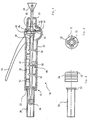
- the applicator 10 shown in FIG. 1 in a first embodiment has a housing 12 on which an actuating element designed as an actuating lever 14 is guided so as to be pivotable.
- the housing 12 also carries a sliding piston rod 16 and carries at its front end 18 a cartridge case 20 of a cartridge, not shown in detail, for holding dental material.
- the cartridge case 20 is detachably connected to the housing 12 via an adapter connection 22, in particular in the form of a bayonet catch.
- the piston rod 16 passes through the housing at its rear end 24 and ends there at a gripping handle 26.
- the gripping handle 26 allows the rod 16 to be manually retracted into an initial position in which the piston rod 16 is in the rightmost position in the drawing according to FIG. 1 extends.
- the applicator 10 has a locking tilting element 28 and an actuating tilting element 30.
- Both canting elements extend essentially annularly around the piston rod 16. In order to ensure the cant due to the inclined position, they each have an inner diameter that is somewhat larger than the outer diameter of the piston rod 16.
- the inner surface of the canting elements 28 and 30 is flat in a manner known per se and ends each with a rather sharp edge in order to ensure the desired clamping action when tilted.
- Both canting elements 28, 30 are resiliently preloaded by compression springs 32 and 34 in the rearward direction of the piston rod, that is to say in the direction of the gripping handle 26.
- the compression springs 32, 34 are each supported on their support projections 36, 38 of the housing 12 at their end remote from the tilting element 28, 30 and extend around the piston rod 16.
- the locking canting element 28 is further supported on one side in a canting element receptacle 40 on the housing 12. Due to the action of the compression spring 32, the locking tilting element 28 is tilted and thus blocks the movement of the piston rod 16 in the reverse direction. On the other hand, a - friction-loaded - movement of the piston rod in the forward direction is possible, since then the piston rod 16 takes the locking canting element 28 somewhat against the action of the compression spring 32 and reduces the canting force.
- a coupling rod 42 On the side opposite the receptacle 40, a coupling rod 42 also acts on the locking canting element 28, likewise against the action of the compression spring 32.
- the coupling rod 42 is supported at its other end via the actuating canting element 30 .
- the coupling rod 42 extends obliquely to the piston rod 16, it being understood that, instead of the embodiment shown, another force-transmitting device, for example also a sleeve, a longitudinal element or the like, is possible for transmitting the compressive force to the locking canting element 28.
- the length of the coupling rod 42 is dimensioned such that in the rest position of the actuating element 14, the coupling rod 42 presses on the locking canting element 28 such that it releases the piston rod 16.
- the piston rod 16 is thus freely movable.
- the actuation tilting element 30 extends in a similar manner Like the locking tilting element 28 around the piston rod 16. Accordingly, the actuating tilting element 30 is able to hold onto the piston rod 16 at least in one direction when it is tilted. While the locking tilting element 28 is supported in a receptacle 40 both in the forward direction and in the backward direction, the actuating tilting element lies only on one side against a support stop 44 of the housing. The support stop 44 supports the actuating tilting element 30 in the rearward direction.
- the actuating element 14 has a driver 46 which is fixedly connected to it and is intended for contact with the actuating tilting element 30.
- the actuating tilting element 30 has a contact surface facing in the rearward direction.
- the actuating element 14 is pivotally mounted on the housing 12.
- an axis of the actuating element can extend across the housing.
- the pivot axis of the pivot lever 14 extends approximately in the area of the coupling rod 42 and the actuating tilting element 30.
- the actuating element 14 also has a support point 50 for the coupling rod 42, on the opposite side of the lever 14 with respect to the pivot axis relative to the driver 46.
- the support point 50 thus moves in the reverse direction, so that the coupling rod 42 also moves in the reverse direction moves and the locking tilting element 28 locks according to the action of the compression spring 32.
- the actuation of the actuating element 14 from the rest position shown in Fig. 1 in a working position in which the lever 14 is pivoted counterclockwise and abuts the housing 12 or extends at least in the vicinity, causes that the actuating tilting element first the driver 46 canted and begins to move the piston rod 16 in the forward direction.
- the coupling rod 42 is relieved, so that the locking tilting element 28 begins to tilt.
- the locking tilting element is fully relieved, so that the piston rod 16 can only move forward, but not in the reverse direction.
- the movement of the actuating elements in the working direction is completed.
- the movement of the actuating element 14 can be initiated in the opposite direction. Due to the action of the compression spring 34, which has been pressed together by the joint advance of the actuating tilting element 30 and the piston rod 16, the actuating element 14 moves in the opposite direction with spring support.
- the coupling rod 42 does not initially act on the locking tilting element 28, so that the piston rod 16 is locked in the reverse direction and when the actuating element 14 is released, the actuating tilting element 30 slides along the piston rod 16 in the reverse direction. This takes place until the position of the actuating lever 14 is reached, in which the support point 50 activates the coupling rod 42, in particular pressurizes it.
- the position of the actuating element 14 at which the backward movement of the piston rod 16 begins can be adjusted by a suitable choice of the length of the coupling rod 42 in relation to the distance between the locking tilting element 28 and the support adapter 50.
- the backward movement clearly relieves the mass to be pressed, in order to reliably avoid re-pressing.
- the forward movement of the piston rod 16 minus the small backward movement to avoid re-pressing forms a stroke of the applicator 10 according to the invention.
- the cartridge case 20 can be seen in the state before it is inserted into the housing 12.
- the cartridge case has four adapter projections 50.
- the cartridge contains the viscous mass, in particular the tooth filling material, which can be expressed by the applicator 10 according to the invention.
- the piston rod with its punch 54 provided at the front end, presses on a piston of the cartridge, which thereby releases the tooth filling material, which in particular can be a light-curing tooth filling material.
- the housing 12 has a corrugation 56 on its outer circumference in the region of the front end, which serves to improve handling.
- the adapter connection 22 works in the manner of a bayonet lock.
- Adapter tabs 52 extend evenly around the circumference of the cartridge case 20 and are suitable for engaging in recesses 58, which are shaped accordingly, at the front end of the housing 12.
- the adapter projections are locked on the adapter connection 22, so that the cartridge case 20 is securely and rigidly locked on the housing 12.
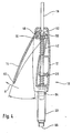
- FIG. 4 An embodiment modified from the embodiment according to FIG. 1 can be seen from FIG. 4.
- the locking tilting element 28 and the actuating tilting element 30 are arranged one behind the other on the piston rod 16.
- the coupling rod 42 extends between the locking tilting element 28 and the area of the actuating tilting element 30. In the rest position shown in FIG. 4, the coupling rod 42 is unloaded, so that the locking tilting element 28 locks on the piston rod 16. In contrast to the embodiment according to FIG. 1, the piston rod 16 cannot therefore be moved freely in the rest position. In addition, there is no movement of the piston rod 16 when the actuating element 14 is relieved into the rest position, which is shown in FIG. 4.
- the actuating element 14 can be moved further in the direction of an arrow A in the opposite direction beyond the rest position, and reaches a release position there. In this position, it acts via the support point 50 in the manner of a two-armed lever on the coupling rod 42 and via the coupling rod 42 on the locking canting element 28 in a position in which the piston rod 16 is released.
- a driver 46 for the actuating tilting element 30 is designed as a correspondingly enlarged projecting surface on the actuating element 14.
- the actuating element 14 can be pivoted on the housing stored, stub axles, which are not visible in the drawing and extend up and down from the plane of the drawing, are mounted in the housing 12.
- the lever forming the actuating element is formed with two legs, the two legs converging in the region of the free end and that both legs laterally along the housing 12 up to the pivot axis 62 extend at which they pass through the housing 12 from the outside inwards and form the support point 50 and the driver 46.
- the entire path of movement of the adapter 10 according to the invention can be seen from FIG. 4 in the area of the cartridge case 20.
- the cartridge case 20 holds the highly viscous mass, not shown, in particular the tooth filling material.
- a piston 64 is adjacent to the housing 12. The piston 64 is moved a little in the working direction by each stroke generated by the actuation of the actuating element 14 until it is adjacent to the outlet end 66 of the cartridge 20. Each time lever 14 is actuated, some tooth filling material is dispensed at exit end 66.
- the piston rod 16 can only be moved exactly up to the position at which the piston 64 has reached its end position.
- the paragraph 68 shown in FIG. 1 is provided, which in this position of the piston 64 comes straight into the area of the actuating tilting element 30. Because of the reduced diameter of the piston rod 16 following the shoulder 68, the actuating tilting element 30 then no longer engages, so that further pressing of the lever 14 does not result in an advance of the piston rod 16.
- FIG. 5 Another embodiment of the applicator according to the invention 10 can be seen from FIG. 5.
- the pivotable guidance of the actuating element 14 is ensured by guide surfaces 47 and 48 which are formed on the pivotable actuating lever 14 and the housing 12.
- the guide surfaces 47 and 48 have a common radius, so that the lever 14 can be pivoted about the pivot axis 62 without it being necessary for stub axles to pass through the housing 12.
- the lever 14 extends in the region of the guide surfaces on both sides of the piston rod 16 and forms both the driver 46 for the actuating tilting element 30 and the support point 50 for the coupling rod 42.
- the coupling rod 42 is additionally slidably supported on the housing 12, specifically by U-shaped receptacles 68 and 70. In this exemplary embodiment as well, the coupling rod 42 extends obliquely over the piston rod 16.
- the arrangement of the receptacle 68 for the coupling rod 42 and the bearing point 36 for the locking canting element 28 is interchanged.
- the coupling rod 42 then extends essentially parallel to the piston rod 16.
- FIG. 6 shows an enlarged detail of the embodiment according to FIG. 5, which shows the transition to the mounting of the coupling rod 42.
- the coupling rod 42 has an adjusting device 72.
- the effective distance between the locking canting element 28 and the pressure surface or support point 50 or the pretensioning of the coupling rod 42 can be set via the adjusting device 72, which can be designed as a knurled nut.
- This points the end of the coupling rod 42 has an external thread 74 and the knurled nut 72 has a corresponding internal thread.
- the knurled nut 72 can be actuated via an opening 76 in the housing.
- the knurled nut 72 is preferably a self-locking nut and its area is covered with a cover, not shown, so that only an adjustment is provided for the setting of the applicator.
- the lever 14 can also be pivoted into a release position by pulling it away from the housing 12. In this position, the pressure surface 50 presses on the actuating device 72 and thus the coupling rod 42 and at the same time also on the actuating tilting element 30, which is lifted off the support 44 fixed to the housing. Both tilting elements 30 and 28 release the piston rod 16 so that it can be moved freely.
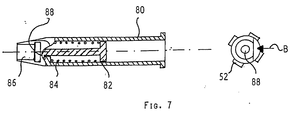
- connection of a spring-loaded adapter is provided, as can be seen in FIG. 7.
- the adapter 80 is provided for engagement on the adapter connection 22 of the housing and has a piston 82 which is spring-loaded in the rearward direction of the piston rod, not shown.
- the piston rod 16 is intended to rest against the piston 82 with its punch 54 or its front end. Due to the spring loading by the compression spring 84, the piston rod is pushed back into its starting position when the movement of the piston rod 16 is released, for example when the lever 14 is actuated into the release position, without the need for manual retraction.
- the adapter 80 is designed to receive a cartridge on its cartridge receptacle 86.
- the cartridge receptacle is open on one side, and a cartridge (not shown) with tooth filling material can be snapped into the adapter 80 made of elastic plastic by being pushed in from the direction of arrow B.
- the piston 82 has a projection 88 at its front end, via which it is held captively in the adapter 80.
- the piston rod 10 is provided with micro-toothing in the engagement area of the actuating tilting element 30.
- the micro-toothing preferably has a sawtooth profile, the depth being approximately 20-100 micrometers, preferably approximately 50 micrometers.
- micro toothing can also be provided in the area of the locking / tilting element (28) if required. Furthermore, it may be simpler for manufacturing reasons to provide the entire piston rod 16 with the micro toothing, which does not impair the function of the solution according to the invention.
Landscapes
- Health & Medical Sciences (AREA)
- Life Sciences & Earth Sciences (AREA)
- Mechanical Engineering (AREA)
- Oral & Maxillofacial Surgery (AREA)
- Dentistry (AREA)
- Epidemiology (AREA)
- Engineering & Computer Science (AREA)
- Animal Behavior & Ethology (AREA)
- General Health & Medical Sciences (AREA)
- Public Health (AREA)
- Veterinary Medicine (AREA)
- Coating Apparatus (AREA)
- Dental Tools And Instruments Or Auxiliary Dental Instruments (AREA)
- Massaging Devices (AREA)
Applications Claiming Priority (2)
| Application Number | Priority Date | Filing Date | Title |
|---|---|---|---|
| DE19618544A DE19618544C1 (de) | 1996-05-08 | 1996-05-08 | Applikator |
| DE19618544 | 1996-05-08 |
Publications (3)
| Publication Number | Publication Date |
|---|---|
| EP0806187A2 true EP0806187A2 (fr) | 1997-11-12 |
| EP0806187A3 EP0806187A3 (fr) | 1999-09-22 |
| EP0806187B1 EP0806187B1 (fr) | 2003-01-22 |
Family
ID=7793740
Family Applications (1)
| Application Number | Title | Priority Date | Filing Date |
|---|---|---|---|
| EP97105034A Expired - Lifetime EP0806187B1 (fr) | 1996-05-08 | 1997-03-25 | Applicateur |
Country Status (6)
| Country | Link |
|---|---|
| US (1) | US5871354A (fr) |
| EP (1) | EP0806187B1 (fr) |
| JP (1) | JP3059690B2 (fr) |
| AT (1) | ATE231365T1 (fr) |
| CA (1) | CA2203855C (fr) |
| DE (2) | DE19618544C1 (fr) |
Cited By (2)
| Publication number | Priority date | Publication date | Assignee | Title |
|---|---|---|---|---|
| US6095814A (en) * | 1999-01-29 | 2000-08-01 | 3M Innovative Properties Company | Dispensing cartridge with stepped chamber |
| WO2007121854A2 (fr) | 2006-04-22 | 2007-11-01 | Bayer Animal Health Gmbh | Applicateur à récipient interchangeable |
Families Citing this family (11)
| Publication number | Priority date | Publication date | Assignee | Title |
|---|---|---|---|---|
| JP4137281B2 (ja) * | 1999-04-28 | 2008-08-20 | 株式会社ジーシー | 歯科用粘性材料用ディスペンサー |
| DE20017314U1 (de) * | 2000-10-10 | 2002-02-21 | Schütz-Dental GmbH, 61191 Rosbach | Vorrichtung zur Dosierung von fliessfähigen Stoffen |
| SE524714C2 (sv) * | 2002-06-28 | 2004-09-21 | Asept Medical Ab | Beredare och applikator för bencement |
| JP4503455B2 (ja) * | 2005-02-08 | 2010-07-14 | 株式会社ジーシー | 歯科用粘性材料用ディスペンサー |
| DE102006037623B4 (de) * | 2006-08-10 | 2010-06-02 | Henkel Ag & Co. Kgaa | Kartuschenpistole |
| DE102006035476A1 (de) * | 2006-12-04 | 2008-06-05 | Hilti Ag | Auspressgerät |
| DE102007000118B4 (de) * | 2007-02-28 | 2015-05-07 | Hilti Aktiengesellschaft | Auspressgerät |
| GB0809545D0 (en) * | 2008-05-28 | 2008-07-02 | 3M Innovative Properties Co | Device for dispensing a dental composition |
| DE102015102463A1 (de) * | 2015-02-20 | 2016-08-25 | Heraeus Medical Gmbh | Austragsvorrichtung für Zementkartuschen mit Federzungen |
| EP3111880B1 (fr) | 2015-07-02 | 2019-03-27 | Ivoclar Vivadent AG | Dispositif d'injection |
| JP6567182B2 (ja) | 2016-06-01 | 2019-08-28 | 株式会社ジーシー | ディスペンサ、並びにディスペンサ及びカートリッジ |
Family Cites Families (8)
| Publication number | Priority date | Publication date | Assignee | Title |
|---|---|---|---|---|
| US4090639A (en) * | 1977-02-14 | 1978-05-23 | Smithkline Corporation | Multiple dose paste dispenser |
| AU541325B2 (en) * | 1979-04-10 | 1985-01-03 | Wellcome Foundation Limited, The | Dose dispensing of pastes |
| IT1168101B (it) * | 1981-01-15 | 1987-05-20 | Domenico Colombo | Siringa a pressione manuale perfezionata, per uso odontoiatrico |
| FR2529930A2 (fr) * | 1982-04-28 | 1984-01-13 | Begouen Jean Paul | Perfectionnements aux moyens pour eviter de facon automatique l'ecoulement subsequent des pistolets a mastic |
| JPS6168161A (ja) * | 1984-09-08 | 1986-04-08 | Semedain Kk | 粘着性材料押出装置におけるたれ防止装置 |
| GB8506010D0 (en) * | 1985-03-08 | 1985-04-11 | Ici Plc | Extrusion apparatus |
| US4840294A (en) * | 1988-02-12 | 1989-06-20 | Illinois Tool Works Inc. | Adjustable dispensing tool |
| US5192008A (en) * | 1992-01-23 | 1993-03-09 | Dai Shyun Enterprise Co., Ltd. | Pulling mechanism of an adhesive-dispensing gun |
-
1996
- 1996-05-08 DE DE19618544A patent/DE19618544C1/de not_active Expired - Fee Related
-
1997
- 1997-03-25 AT AT97105034T patent/ATE231365T1/de not_active IP Right Cessation
- 1997-03-25 DE DE59709172T patent/DE59709172D1/de not_active Expired - Lifetime
- 1997-03-25 EP EP97105034A patent/EP0806187B1/fr not_active Expired - Lifetime
- 1997-04-28 CA CA002203855A patent/CA2203855C/fr not_active Expired - Fee Related
- 1997-05-05 US US08/851,365 patent/US5871354A/en not_active Expired - Lifetime
- 1997-05-07 JP JP9134434A patent/JP3059690B2/ja not_active Expired - Fee Related
Cited By (2)
| Publication number | Priority date | Publication date | Assignee | Title |
|---|---|---|---|---|
| US6095814A (en) * | 1999-01-29 | 2000-08-01 | 3M Innovative Properties Company | Dispensing cartridge with stepped chamber |
| WO2007121854A2 (fr) | 2006-04-22 | 2007-11-01 | Bayer Animal Health Gmbh | Applicateur à récipient interchangeable |
Also Published As
| Publication number | Publication date |
|---|---|
| JPH1043206A (ja) | 1998-02-17 |
| EP0806187A3 (fr) | 1999-09-22 |
| DE19618544C1 (de) | 1997-10-23 |
| DE59709172D1 (de) | 2003-02-27 |
| EP0806187B1 (fr) | 2003-01-22 |
| US5871354A (en) | 1999-02-16 |
| JP3059690B2 (ja) | 2000-07-04 |
| CA2203855C (fr) | 2001-01-30 |
| ATE231365T1 (de) | 2003-02-15 |
| CA2203855A1 (fr) | 1997-11-08 |
Similar Documents
| Publication | Publication Date | Title |
|---|---|---|
| DE69312151T2 (de) | Pipettiervorrichtung mit einem Abwerfer für Pipettenspitzen | |
| DE69612483T2 (de) | Handbetätigbare austragevorrichtung mit kraftbegrenzungskupplung | |
| DE4341229C2 (de) | Pipettensystem | |
| EP1032316B1 (fr) | Appareil pour la pose d'agrafes | |
| EP0218877B1 (fr) | Appareil pour le remplissage de cavités dentaires | |
| DE69115623T2 (de) | Schlagwerkzeug mit Klinge | |
| EP0679439B1 (fr) | Pipette de distribution à répétition | |
| EP0589828A2 (fr) | Mécanisme d'avancement d'un appareil d'extrusion | |
| DE2406568A1 (de) | Verfahren und vorrichtung zum abgeben des fuellmaterials aus einer tube | |
| EP0806187B1 (fr) | Applicateur | |
| EP0615787A1 (fr) | Distributeur manuel pour cartouche double | |
| DE9415847U1 (de) | Repetierpipette | |
| EP0885599B1 (fr) | Applicateur | |
| DE10020591B4 (de) | Ausgabevorrichtung für viskoses Dentalmaterial | |
| DE10259777B4 (de) | Brennkraftbetriebenes Arbeitsgerät, insbesondere Setzgerät für Befestigungselemente | |
| EP2049270A1 (fr) | Pistolet à cartouche | |
| EP4052793A1 (fr) | Dispositif de mise en pipettes | |
| DE7817873U1 (de) | Pistole zur Verbindung mit Kartuschen | |
| DE102010030841A1 (de) | Auspressvorrichtung | |
| DE29720952U1 (de) | Magazin für ein chirurgisches Clipanlegegerät | |
| EP4340776B1 (fr) | Injecteur pour lentille intraoculaire | |
| DE4142603A1 (de) | Behaelter fuer ein festes kosmetikum | |
| DE2609671A1 (de) | Mechanischer druckbleitstift mit beweglichem schaftspitzenteil | |
| DE10058283A1 (de) | Kartuschensystem | |
| EP0893974A1 (fr) | Pistolet doseur utilisable avec des cartouches dentaires |
Legal Events
| Date | Code | Title | Description |
|---|---|---|---|
| PUAI | Public reference made under article 153(3) epc to a published international application that has entered the european phase |
Free format text: ORIGINAL CODE: 0009012 |
|
| AK | Designated contracting states |
Kind code of ref document: A2 Designated state(s): AT CH DE FR GB IT LI SE |
|
| PUAL | Search report despatched |
Free format text: ORIGINAL CODE: 0009013 |
|
| AK | Designated contracting states |
Kind code of ref document: A3 Designated state(s): AT CH DE FR GB IT LI SE |
|
| RIC1 | Information provided on ipc code assigned before grant |
Free format text: 6A 61C 5/06 A, 6B 05C 17/01 B, 6A 61C 9/00 B |
|
| 17P | Request for examination filed |
Effective date: 19991020 |
|
| RAP1 | Party data changed (applicant data changed or rights of an application transferred) |
Owner name: IVOCLAR VIVADENT AG |
|
| 17Q | First examination report despatched |
Effective date: 20020516 |
|
| GRAH | Despatch of communication of intention to grant a patent |
Free format text: ORIGINAL CODE: EPIDOS IGRA |
|
| GRAH | Despatch of communication of intention to grant a patent |
Free format text: ORIGINAL CODE: EPIDOS IGRA |
|
| GRAA | (expected) grant |
Free format text: ORIGINAL CODE: 0009210 |
|
| AK | Designated contracting states |
Kind code of ref document: B1 Designated state(s): AT CH DE FR GB IT LI SE |
|
| REG | Reference to a national code |
Ref country code: GB Ref legal event code: FG4D Free format text: NOT ENGLISH |
|
| REG | Reference to a national code |
Ref country code: CH Ref legal event code: NV Representative=s name: KELLER & PARTNER PATENTANWAELTE AG Ref country code: CH Ref legal event code: EP |
|
| REF | Corresponds to: |
Ref document number: 59709172 Country of ref document: DE Date of ref document: 20030227 Kind code of ref document: P |
|
| REG | Reference to a national code |
Ref country code: SE Ref legal event code: TRGR |
|
| GBT | Gb: translation of ep patent filed (gb section 77(6)(a)/1977) |
Effective date: 20030519 |
|
| ET | Fr: translation filed | ||
| PLBE | No opposition filed within time limit |
Free format text: ORIGINAL CODE: 0009261 |
|
| STAA | Information on the status of an ep patent application or granted ep patent |
Free format text: STATUS: NO OPPOSITION FILED WITHIN TIME LIMIT |
|
| 26N | No opposition filed |
Effective date: 20031023 |
|
| PGFP | Annual fee paid to national office [announced via postgrant information from national office to epo] |
Ref country code: AT Payment date: 20060316 Year of fee payment: 10 |
|
| PG25 | Lapsed in a contracting state [announced via postgrant information from national office to epo] |
Ref country code: AT Free format text: LAPSE BECAUSE OF NON-PAYMENT OF DUE FEES Effective date: 20070325 |
|
| PGFP | Annual fee paid to national office [announced via postgrant information from national office to epo] |
Ref country code: SE Payment date: 20080320 Year of fee payment: 12 |
|
| EUG | Se: european patent has lapsed | ||
| PG25 | Lapsed in a contracting state [announced via postgrant information from national office to epo] |
Ref country code: SE Free format text: LAPSE BECAUSE OF NON-PAYMENT OF DUE FEES Effective date: 20090326 |
|
| REG | Reference to a national code |
Ref country code: CH Ref legal event code: PCAR Free format text: NEW ADDRESS: EIGERSTRASSE 2 POSTFACH, 3000 BERN 14 (CH) |
|
| REG | Reference to a national code |
Ref country code: FR Ref legal event code: PLFP Year of fee payment: 20 |
|
| PGFP | Annual fee paid to national office [announced via postgrant information from national office to epo] |
Ref country code: CH Payment date: 20160322 Year of fee payment: 20 Ref country code: DE Payment date: 20160322 Year of fee payment: 20 |
|
| PGFP | Annual fee paid to national office [announced via postgrant information from national office to epo] |
Ref country code: GB Payment date: 20160322 Year of fee payment: 20 Ref country code: FR Payment date: 20160322 Year of fee payment: 20 |
|
| PGFP | Annual fee paid to national office [announced via postgrant information from national office to epo] |
Ref country code: IT Payment date: 20160318 Year of fee payment: 20 |
|
| REG | Reference to a national code |
Ref country code: DE Ref legal event code: R079 Ref document number: 59709172 Country of ref document: DE Free format text: PREVIOUS MAIN CLASS: A61C0005060000 Ipc: A61C0005600000 |
|
| REG | Reference to a national code |
Ref country code: DE Ref legal event code: R071 Ref document number: 59709172 Country of ref document: DE |
|
| REG | Reference to a national code |
Ref country code: CH Ref legal event code: PL |
|
| REG | Reference to a national code |
Ref country code: GB Ref legal event code: PE20 Expiry date: 20170324 |
|
| PG25 | Lapsed in a contracting state [announced via postgrant information from national office to epo] |
Ref country code: GB Free format text: LAPSE BECAUSE OF EXPIRATION OF PROTECTION Effective date: 20170324 |