EP0806236B1 - Procédé et appareil pour éliminer les oxydes d'azote des gaz de combustion - Google Patents
Procédé et appareil pour éliminer les oxydes d'azote des gaz de combustion Download PDFInfo
- Publication number
- EP0806236B1 EP0806236B1 EP97106610A EP97106610A EP0806236B1 EP 0806236 B1 EP0806236 B1 EP 0806236B1 EP 97106610 A EP97106610 A EP 97106610A EP 97106610 A EP97106610 A EP 97106610A EP 0806236 B1 EP0806236 B1 EP 0806236B1
- Authority
- EP
- European Patent Office
- Prior art keywords
- waste gas
- economiser
- combustion
- mentioned
- stage
- Prior art date
- Legal status (The legal status is an assumption and is not a legal conclusion. Google has not performed a legal analysis and makes no representation as to the accuracy of the status listed.)
- Expired - Lifetime
Links
Images
Classifications
-
- B—PERFORMING OPERATIONS; TRANSPORTING
- B01—PHYSICAL OR CHEMICAL PROCESSES OR APPARATUS IN GENERAL
- B01D—SEPARATION
- B01D53/00—Separation of gases or vapours; Recovering vapours of volatile solvents from gases; Chemical or biological purification of waste gases, e.g. engine exhaust gases, smoke, fumes, flue gases, aerosols
- B01D53/34—Chemical or biological purification of waste gases
- B01D53/74—General processes for purification of waste gases; Apparatus or devices specially adapted therefor
- B01D53/86—Catalytic processes
- B01D53/8621—Removing nitrogen compounds
- B01D53/8625—Nitrogen oxides
- B01D53/8631—Processes characterised by a specific device
-
- F—MECHANICAL ENGINEERING; LIGHTING; HEATING; WEAPONS; BLASTING
- F23—COMBUSTION APPARATUS; COMBUSTION PROCESSES
- F23J—REMOVAL OR TREATMENT OF COMBUSTION PRODUCTS OR COMBUSTION RESIDUES; FLUES
- F23J15/00—Arrangements of devices for treating smoke or fumes
- F23J15/006—Layout of treatment plant
-
- F—MECHANICAL ENGINEERING; LIGHTING; HEATING; WEAPONS; BLASTING
- F23—COMBUSTION APPARATUS; COMBUSTION PROCESSES
- F23J—REMOVAL OR TREATMENT OF COMBUSTION PRODUCTS OR COMBUSTION RESIDUES; FLUES
- F23J15/00—Arrangements of devices for treating smoke or fumes
- F23J15/06—Arrangements of devices for treating smoke or fumes of coolers
-
- F—MECHANICAL ENGINEERING; LIGHTING; HEATING; WEAPONS; BLASTING
- F23—COMBUSTION APPARATUS; COMBUSTION PROCESSES
- F23J—REMOVAL OR TREATMENT OF COMBUSTION PRODUCTS OR COMBUSTION RESIDUES; FLUES
- F23J2215/00—Preventing emissions
- F23J2215/10—Nitrogen; Compounds thereof
-
- F—MECHANICAL ENGINEERING; LIGHTING; HEATING; WEAPONS; BLASTING
- F23—COMBUSTION APPARATUS; COMBUSTION PROCESSES
- F23J—REMOVAL OR TREATMENT OF COMBUSTION PRODUCTS OR COMBUSTION RESIDUES; FLUES
- F23J2217/00—Intercepting solids
- F23J2217/40—Intercepting solids by cyclones
-
- F—MECHANICAL ENGINEERING; LIGHTING; HEATING; WEAPONS; BLASTING
- F23—COMBUSTION APPARATUS; COMBUSTION PROCESSES
- F23J—REMOVAL OR TREATMENT OF COMBUSTION PRODUCTS OR COMBUSTION RESIDUES; FLUES
- F23J2219/00—Treatment devices
- F23J2219/10—Catalytic reduction devices
Definitions
- the invention relates to a method for reducing nitrogen oxide from combustion exhaust gases, in particular of combustion exhaust gases from waste incineration plants and a plant for Execution of the procedure.
- the upper limit is on the one hand due to the softening and agglomeration behavior repeatedly occurring dust compositions, e.g. B. alkali-rich dust, set, on the other hand, an undesired, excessive conversion of SO 2 to SO 3 is to be prevented by the upper limit.
- this upper temperature limit is around 300 to 350 ° C.
- the lower limit is determined by the possibility of ammonium bisulfate formation in the DENOX reactor under certain operating conditions. This lower temperature limit is around 250 to 300 ° C, depending on the SO x and NH 3 content of the combustion gases.
- the DENOX reactor is seen directly in the flow direction of the combustion exhaust gas after the combustion exhaust gas emerges from the steam generator heating surfaces of the waste incineration plant arranged, the combustion exhaust gas usually occurs at a temperature below or equal to the required catalyst operating temperature or, in rare cases, it emerges at a temperature above the required catalytic converter operating temperature the incinerator.
- the combustion exhaust gas occurs below the minimum allowable Catalytic converter operating temperature, which is especially in the partial load range of the incinerator occurs, the exhaust gas temperature must be regulated. This is done through use of additional burners, e.g. B. duct burners or heat exchangers to increase the temperature of the combustion exhaust gas.
- additional burners e.g. B. duct burners or heat exchangers to increase the temperature of the combustion exhaust gas.
- the disadvantage here is that when using channel burners Additional primary energy consumption takes place or exergetic when using heat exchangers valuable steam or other is used.
- the combustion exhaust gas occurs above the maximum permissible catalytic converter operating temperature off, the exhaust gas temperature must be reduced. This is preferably done by the use of injection or evaporative coolers to lower the temperature of the combustion gases.
- the disadvantage here is a deterioration in the efficiency of the overall system the liquid evaporation in the exhaust gas flow and the increase in volume of the exhaust gas the additional steam introduced.
- a disadvantage of this known system is the primary energy consumption mentioned above Increase in temperature of the combustion exhaust gas and the associated operating costs as well the investment costs of the burners.
- Document DE OS 27 33 408 is a boiler device with a furnace, one Flue gas duct and arranged in this heat exchanger stages as well as with at least one a denitrator charged to a catalyst in one of the optimal reaction temperature of the catalyst corresponding denitrator section of the flue gas duct for denitration of the flue gas known.
- a separate bypass duct with control devices or devices is provided through which if necessary, part of the flue gas is removed before the first heat exchanger stage at which first heat exchanger stage is passed uncooled and downstream of this heat exchanger stage and upstream of the denitrator the flue gas flow in the flue gas duct again is fed.
- the disadvantage of this arrangement is the complex bypass channel, including the necessary control devices as well as the fact that to control the optimal reaction temperature the catalytic converter can only be operated on the flue gas side while the water / steam side no possibility of intervening in the temperature control is possible. It is also not advantageous that the main flue gas flow in the flue gas duct enters laterally through the bypass duct warmer flue gas partial flow is mixed, since both flows up to the entry into the denitrator have not mixed homogeneously and consequently there is sometimes no optimal reaction temperature before the denitrator.
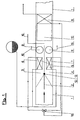
- Fig. 1 shows a schematic representation of the route of the combustion exhaust gas of a waste incineration plant after the immediate exit from a waste incineration plant, not shown inside the exhaust pipe 1, the flow direction of the exhaust gas is indicated by the direction of the arrow.
- the exhaust pipe 1 formed two lines.
- the two exhaust lines 3, 4 are each with an economizer package 6, 7 of a first economizer stage 5 and the entrance to the exhaust lines 3, 4 is formed with a gas switch 2.
- the gas switch 2 enables the flow through both exhaust gas lines 3, 4 in the central position, as shown in FIG. 1 and in the switch position (shown in broken lines in FIG. 1) the flow through the exhaust gas lines 3 or 4 through the combustion exhaust gas.
- first economist level 5 and second Economizer level 11 (in the course of the further description) is in relation to the flow direction of the combustion exhaust gas defined.
- the respective economizer packages 6, 7 of the first economizer stage 5 are preferred at least one each in the flow direction of the exhaust gas within the exhaust line 3, 4 Separators 8, 9 downstream for separating solids from the combustion exhaust gas.
- the cross sections of the two exhaust lines 3, 4, the thermal design parameters of the two economizer packages 6, 7 of the first economizer level 5 and the dedusting performance of the two separators 8, 9 are preferably of the same size and the economizer packages 6, 7 and Separators 8, 9 formed parallel to each other to different pressure losses or exhaust gas flows with different temperatures in the exhaust lines 3, 4 and in the DENOX reactor 10 to prevent.
- the exhaust lines 3, 4 are also preferred trained parallel to each other.
- the thermal design parameters and thus the size of the economizer packages 6, 7 of the first economizer stage 5 preferably designed such that the combustion exhaust gas at 110% combustion plant output, based on the nominal load, and at the end the steam generator travel time is cooled to an exhaust gas temperature which is the maximum DENOX reactor operating temperature, e.g. B. 320 ° C, corresponds (the measurement of the exhaust gas temperature and thus the operating temperature occurs directly in the flow direction of the exhaust gas in front of the DENOX reactor 10 or possibly in the DENOX reactor 10 by means 16 for temperature detection).
- the maximum DENOX reactor operating temperature e.g. B. 320 ° C
- Partial load range of the incinerator of preferably 60 - 80%, based on the nominal load the incinerator, one of the two exhaust lines 3, 4 is blocked by the gas switch 2.
- the drive 12, not shown, of the gas switch 2 is dependent on a control means 13 of the partial load range controlled.
- a small proportion of preferably 5- 50% of the total working medium is supplied.
- the measures according to the invention make it possible to remove combustion exhaust gases from a Waste incineration plant operating within a load range of approx. 50 - 110% of the nominal load is operated within a predetermined DENOX reactor operating temperature range of 250 - 350 ° C, preferably within a "temperature window" of 280 - 320 ° C, in one DENOX reactor 10 by selective catalytic reduction (SCR process) largely from To reduce nitrogen oxides without using primary energy to increase the temperature of the exhaust gas or Use of injection or evaporative coolers to lower the temperature of the exhaust gas.
- SCR process selective catalytic reduction
- the combustion exhaust gas is known by means 15 in FIG Way reducing agents, e.g. B. ammonia or an aqueous ammonia solution, for the selective abandoned catalytic reduction in DENOX reactor 10 equipped with DENOX catalysts.
- the reducing agent is preferably added in the separator 8, 9. Are not Separators 8, 9 are provided, so the reducing agent is between the first economizer stage 5 and DENOX reactor 10 added in the exhaust lines 3, 4 by means 15.
- the combustion exhaust gas only passed through an exhaust line 3, 4, so also the supply of Reducing agent in the blocked off exhaust route 4, 3.
- the combustion exhaust gas through a downstream of the DENOX reactor 10 passed second economizer stage 11 and thereby further to a desired exhaust gas temperature cooled down, for example to 230 ° C exhaust gas temperature.
- the second economizer level 11 which is connected to the first economizer level 5 on the water side, is preferably integrated into the housing of the DENOX reactor 10 and this in the exhaust gas flow direction seen immediately downstream.
- the measure is advantageously an inexpensive and compact design of the DENOX reactor 10 achieved with integrated second economizer level 11 and the overall system.
- the combustion exhaust gas can be downstream of the second economizer stage 11 in a known manner undergo further after-treatment before being discharged into the atmosphere.
Landscapes
- Engineering & Computer Science (AREA)
- Chemical & Material Sciences (AREA)
- General Engineering & Computer Science (AREA)
- Environmental & Geological Engineering (AREA)
- Mechanical Engineering (AREA)
- Health & Medical Sciences (AREA)
- Biomedical Technology (AREA)
- Analytical Chemistry (AREA)
- General Chemical & Material Sciences (AREA)
- Oil, Petroleum & Natural Gas (AREA)
- Chemical Kinetics & Catalysis (AREA)
- Chimneys And Flues (AREA)
- Treating Waste Gases (AREA)
Claims (26)
- Méthode pour la réduction d'oxyde azotique contenu dans des gaz de combustion, en particulier des gaz de combustion produits dans des usines d'incinération des ordures ménagères, lors de laquelle le gaz de fumée sortant de l'installation d'incinération par un carneau de gaz de fumée est dénitrifié à l'aide d'un agent de réduction dans un réacteur DENOX au moyen d'une méthode de réduction catalytique sélective, le gaz de fumée étant refroidi par un premier étage d'économiseur (5) à un domaine de température de service prédéfini du réacteur DENOX avant d'entrer dans le réacteur DENOX (10) et suite à la dénitrification se passant dans le réacteur DENOX (10) le refroidissement du gaz de fumée étant continué jusqu'à une température de gaz de fumée prédéfinie dans un deuxième étage d'économiseur (11) étant connecté au premier étage d'économiseur (5) du côté d'eau, le premier étage d'économiseur (5) étant formé de deux faisceaux d'économiseur (6, 7), qui sont arrangés en parallèle au côté d'eau, et chacun des faisceaux d'économiseur (6, 7) étant disposé dans une propre ligne de gaz de fumée (3, 4) et l'entrée dans les lignes de gaz de fumée (3, 4) étant équipée d'un dispositif de distribution de gaz (2), qui est réglable et sert à mettre au point la température de gaz de combustion et qui lors du passage en dessous d'une plage de charge partielle prédéfinie de l'installation de combustion est réglé de la position Ouvert en position Fermé en coupant une ligne de gaz de fumée (3, 4) et qui lors du passage en dessus de la plage de charge partielle prédéfinie est réglé de la position Fermé en position Ouvert en libérant les deux lignes de gaz de fumée (3, 4), la quantité d'eau d'alimentation du faisceau d'économiseur (6, 7) passant à travers, auquel de gaz de combustion est admis, étant réglée pour mettre au point la température de gaz de combustion lors de l'opération utilisant une ligne de gaz de fumée (3, 4) coupée .
- Méthode selon la revendication 1, caractérisée en ce que le gaz de combustion est refroidi par le premier étage d'économiseur (5) à un domaine de température de service DENOX prédéfini de 250 - 350 °C.
- Méthode selon la revendication 1, caractérisée en ce que le gaz de combustion est refroidi par le premier étage d'économiseur (5) à un domaine de température de service DENOX prédéfini de 280 - 320 °C.
- Méthode selon l'une quelconque des revendications précédentes, caractérisée en ce que lors d'une admission d'eau d'alimentation d'une même quantité aux deux faisceaux d'économiseur (6, 7), pour l'essentiel le refroidissement du gaz de combustion atteint le même niveau sous l'effet des mêmes paramètres thermiques d'engineering des deux faisceaux d'économiseur (6, 7) dans les lignes de gaz de fumée respectives (3, 4).
- Méthode selon l'une quelconque des revendications précédentes, caractérisée en ce que le gaz de combustion entre le premier étage d'économiseur (5) et le réacteur DENOX (10) est nettoyé de matières solides par des dépoussiéreurs (8, 9), le gaz de fumée étant nettoyé dans chaque ligne de gaz de fumée (3, 4) par au moins un dépoussiéreur (8, 9).
- Méthode selon l'une quelconque des revendications précédentes, caractérisée en ce que la capacité de séparation des dépoussiéreurs (8, 9) dans les lignes de gaz de fumée respectives (3, 4) atteint le même niveau.
- Méthode selon l'une quelconque des revendications précédentes, caractérisée en ce que le nettoyage du gaz de fumée de matières solides dans les lignes de gaz de fumée respectives (3, 4) est effectué moyennant une séparation par cyclone.
- Méthode selon l'une quelconque des revendications précédentes, caractérisée en ce que l'agent de réduction est ajouté au gaz de combustion par des installations (15) disposées à l'intérieur des lignes de gaz de fumée (3, 4) et / ou des dépoussiéreurs (8, 9).
- Méthode selon l'une quelconque des revendications précédentes, caractérisée en ce que regardant en direction du courant du gaz de fumée, lors du passage du gaz à travers des deux lignes de gaz de fumée (3, 4) les mêmes conditions de courant et de pression existent pour l'essentiel à la sortie du gaz de combustion des lignes de gaz de fumée (3, 4).
- Méthode selon l'une quelconque des revendications précédentes, caractérisée en ce que lors d'une coupure d'une ligne de gaz de fumée (3, 4) et de l'admission de gaz de combustion seulement à un faisceau d'économiseur (6, 7) 5 - 50 % d'eau d'alimentation, par rapport à la quantité totale, est admise à ce faisceau d'économiseur.
- Méthode selon l'une quelconque des revendications précédentes, caractérisée en ce que des gaz de combustion sont nettoyés dons la plage de charge entre 50 et 110 % de l'installation de combustion, par rapport à la charge nominale,
- Méthode selon l'une quelconque des revendications précédentes, caractérisée en ce que la plage de charge partielle, par rapport à la charge nominale de l'installation de combustion, utilisée pour le changement de marche du dispositif de distribution de gaz (2) est à 60 - 80 %.
- Méthode selon l'une quelconque des revendications précédentes, caractérisée en ce que les paramètres thermiques d'engineering du premier étage d'économiseur (5) sont conçus tellement, que le gaz de combustion, à une capacité de l'installation de combustion de 110 %, par rapport à la charge nominale, et à la fin de la durée de service du générateur de vapeur, est refroidi à une température de gaz de fumée, qui correspond à la température maximale de service du réacteur DENOX.
- Installation pour la réduction d'oxyde azotique contenu dans des gaz de combustion, en particulier des gaz de combustion produits dans des usines d'incinération des ordures ménagères comprenant
une installation de combustion avec un carneau de gaz de fumée (1) et un réacteur DENOX (10), qui est destiné à la réduction catalytique sélective, une partie du carneau de gaz de fumée (1) disposée en amont du réacteur DENOX (10) étant constituée de deux lignes de gaz de fumée (3, 4), à l'entrée desquelles un dispositif de distribution de gaz (2) est installé, qui est réglable et sert à mettre au point la température de gaz de combustion, et chacune des deux lignes de gaz de fumée étant équipée d'un faisceau d'économiseur (6, 7) formant un premier étage d'économiseur (5) et étant destiné au réglage de la température de gaz de fumée à un domaine de température de service du réacteur DENOX prédéfini, les faisceaux d'économiseur (6, 7) étant arrangés en parallèle au côté d'eau,
un deuxième étage d'économiseur (11) connecté au premier étage d'économiseur (5) au côté d'eau, qui est arrangé directement en aval du réacteur DENOX (10) en direction du courant du gaz de fumée passant à travers,
comprenant des installations (12, 13) pour le réglage et l'actionnement du dispositif de distribution de gaz (2) en position Ouvert ou Fermé pour admettre de gaz de fumée à un ou deux faisceaux d'économiseur (6, 7) dépendant d'une plage de charge partielle prédéfinie de l'installation de combustion
et la quantité d'eau d'alimentation passant à travers du faisceau d'économiseur (6, 7), auquel de gaz de combustion est admis, étant réglable pour mettre au point la température de gaz de combustion lors de l'admission d'une seule ligne de gaz de fumée (3, 4). - Installation selon la revendication 14, caractérisée en ce que le deuxième étage d'économiseur (11) est intégré dans le réacteur DENOX (10).
- Installation selon la revendication 14 ou 15, caractérisée en ce qu'en position Fermé du dispositif de distribution de gaz (2) soit la ligne de gaz de fumée (3) soit la ligne de gaz de fumée (4) est coupée.
- Installation selon l'une quelconque des revendications précédentes 14 à 16, caractérisée en ce que pour le nettoyage du gaz de fumée de matières solides chaque ligne de gaz de fumée (3, 4) est équipée au moins d'un dépoussiéreur (8, 9) en aval des faisceaux d'économiseur (6, 7) en direction du courant du gaz de fumée.
- Installation selon l'une quelconque des revendications précédentes 14 à 17, caractérisée en ce que les dépoussiéreurs (8, 9) des lignes de gaz de fumée respectives (3, 4) ont la même capacité de séparation.
- Installation selon l'une quelconque des revendications précédentes 14 à 18, caractérisée en ce que les dépoussiéreurs (8, 9) sont des dépoussiéreurs à cyclone.
- Installation selon l'une quelconque des revendications précédentes 14 à 19, caractérisée en ce que les paramètres thermiques d'engineering des faisceaux d'économiseur (6, 7) sont identiques.
- Installation selon l'une quelconque des revendications précédentes 14 à 20, caractérisée en ce que les faisceaux d'économiseur (6, 7) à l'intérieur de la ligne de gaz de fumée respective (3, 4) sont disposés en parallèle.
- Installation selon l'une quelconque des revendications précédentes 14 à 21, caractérisée en ce que les dépoussiéreurs (8, 9) à l'intérieur de la ligne de gaz de fumée respective (3, 4) sont disposés en parallèle.
- Installation selon l'une quelconque des revendications précédentes 14 à 22, caractérisée en ce que les lignes de gaz de fumée (3, 4) sont disposées en parallèle.
- Installation selon l'une quelconque des revendications précédentes 14 à 23, caractérisée en ce que les sections des lignes de gaz de fumée (3, 4) ont les mêmes dimensions.
- Installation selon l'une quelconque des revendications précédentes 14 à 24, caractérisée en ce que les lignes de gaz de fumée (3, 4) et/ou les dépoussiéreurs (8, 9) sont équipés d'installations (15) prévues pour l'alimentation d'agents de réduction.
- Installation selon l'une quelconque des revendications précédentes 14 à 25, caractérisée en ce que les paramètres thermiques d'engineering du premier étage d'économiseur (5) sont conçus tellement, que le gaz de combustion, à une capacité de l'installation de combustion de 110 %, par rapport à la charge nominale, et à la fin de la durée de service du générateur de vapeur, est refroidi à une température de gaz de fumée, qui correspond à la température maximale de service du réacteur DENOX.
Applications Claiming Priority (2)
| Application Number | Priority Date | Filing Date | Title |
|---|---|---|---|
| DE19618384 | 1996-05-08 | ||
| DE19618384A DE19618384C2 (de) | 1996-05-08 | 1996-05-08 | Verfahren zur Stickoxidminderung von Verbrennungsabgasen und Anlage zur Durchführung des Verfahrens |
Publications (2)
| Publication Number | Publication Date |
|---|---|
| EP0806236A1 EP0806236A1 (fr) | 1997-11-12 |
| EP0806236B1 true EP0806236B1 (fr) | 2003-01-02 |
Family
ID=7793638
Family Applications (1)
| Application Number | Title | Priority Date | Filing Date |
|---|---|---|---|
| EP97106610A Expired - Lifetime EP0806236B1 (fr) | 1996-05-08 | 1997-04-22 | Procédé et appareil pour éliminer les oxydes d'azote des gaz de combustion |
Country Status (4)
| Country | Link |
|---|---|
| EP (1) | EP0806236B1 (fr) |
| CZ (1) | CZ105497A3 (fr) |
| DE (2) | DE19618384C2 (fr) |
| PL (1) | PL319826A1 (fr) |
Cited By (1)
| Publication number | Priority date | Publication date | Assignee | Title |
|---|---|---|---|---|
| US8751413B2 (en) | 2011-07-26 | 2014-06-10 | General Electric Company | Fuzzy logic based system monitoring system and method |
Families Citing this family (5)
| Publication number | Priority date | Publication date | Assignee | Title |
|---|---|---|---|---|
| DE19645585C2 (de) * | 1996-08-22 | 1999-01-28 | Ralf Groschwitz | Verfahren und Vorrichtung zur Reinigung von Verbrennungsabgasen unterschiedlicher Strömungsrate und/oder Temperatur |
| DE20112489U1 (de) | 2001-07-28 | 2001-10-25 | Balcke-Dürr Energietechnik GmbH, 46049 Oberhausen | Vorrichtung zur Nachbehandlung von Reaktionsgasen |
| US8659415B2 (en) | 2011-07-15 | 2014-02-25 | General Electric Company | Alarm management |
| EP2962743A1 (fr) | 2014-07-04 | 2016-01-06 | Alstom Technology Ltd | Chaudière et procédé de commande d'émissions de NOx provenant d'une chaudière comprenant SNCR |
| PL3712498T3 (pl) * | 2019-03-19 | 2022-04-25 | Doosan Lentjes Gmbh | Sposób obsługi spalarni odpadów materiałów stałych |
Family Cites Families (6)
| Publication number | Priority date | Publication date | Assignee | Title |
|---|---|---|---|---|
| CA1092910A (fr) * | 1976-07-27 | 1981-01-06 | Ko'hei Hamabe | Chaudiere avec dispositif de denitrification |
| JPS5479160A (en) * | 1977-12-07 | 1979-06-23 | Hitachi Ltd | Denitration method for exhaust gas |
| US4737345A (en) * | 1981-04-20 | 1988-04-12 | Werner Henke | System for efficiently removing oxides of nitrogen from exhaust gas |
| DE3516831A1 (de) * | 1985-05-10 | 1986-11-13 | Ferdinand Lentjes, Dampfkessel- und Maschinenbau, 4000 Düsseldorf | Verfahren und vorrichtung zum betreiben eines regenerativ-gasvorwaermers |
| US4756890A (en) * | 1986-05-09 | 1988-07-12 | Pyropower Corporation | Reduction of NOx in flue gas |
| DE3636554A1 (de) * | 1986-10-28 | 1988-05-19 | Balcke Duerr Ag | Verfahren und vorrichtung zum entsticken von stickoxid-beladenen rauchgasen eines mit schwefelhaltigem brennstoff betriebenen dampferzeugers |
-
1996
- 1996-05-08 DE DE19618384A patent/DE19618384C2/de not_active Expired - Fee Related
-
1997
- 1997-04-04 CZ CZ971054A patent/CZ105497A3/cs unknown
- 1997-04-22 EP EP97106610A patent/EP0806236B1/fr not_active Expired - Lifetime
- 1997-04-22 DE DE59709038T patent/DE59709038D1/de not_active Expired - Fee Related
- 1997-05-06 PL PL97319826A patent/PL319826A1/xx unknown
Cited By (1)
| Publication number | Priority date | Publication date | Assignee | Title |
|---|---|---|---|---|
| US8751413B2 (en) | 2011-07-26 | 2014-06-10 | General Electric Company | Fuzzy logic based system monitoring system and method |
Also Published As
| Publication number | Publication date |
|---|---|
| PL319826A1 (en) | 1997-11-10 |
| DE19618384C2 (de) | 1999-01-21 |
| DE19618384A1 (de) | 1997-11-13 |
| EP0806236A1 (fr) | 1997-11-12 |
| CZ105497A3 (en) | 1997-11-12 |
| DE59709038D1 (de) | 2003-02-06 |
Similar Documents
| Publication | Publication Date | Title |
|---|---|---|
| EP0745807B1 (fr) | Chaudière à vapeur | |
| DE2733408C3 (de) | Rauchgaszug einer Kesselanlage | |
| DE3877513T2 (de) | Apparat zur troepfchenabscheidung durch unterkuehlung. | |
| DE3532281C2 (de) | Verfahren und anlage zur beeinflussung der abgase eines wirbelbettkessels | |
| DE3614385A1 (de) | Verfahren und vorrichtung zum reinigen von abgasen | |
| DE69604027T2 (de) | Kessel mit Denitrierungsvorrichtung | |
| EP0806236B1 (fr) | Procédé et appareil pour éliminer les oxydes d'azote des gaz de combustion | |
| EP0502443B1 (fr) | Préchauffeur à régénération et méthode d'opération dudit système | |
| EP1350552B1 (fr) | Procédé et dispositif pour éliminer l'ammoniac des gaz de fumée | |
| WO1984002175A1 (fr) | Procede et installation de rechauffage de gaz de combustion desulfures | |
| DE4310962C1 (de) | Gemeinsame Abgasanlage für mehrere Brennkraftmaschinen mit Entstickung des Abgases durch selektive katalytische Reduktion | |
| DE69522635T2 (de) | Methode eine Denitrierungsvorrichtung für einen kohlegefeuerten Kessel zu betreiben | |
| DE3407277C2 (de) | Verfahren und Vorrichtung zur Reinigung von Rauchgas | |
| DE69106965T2 (de) | Vorrichtung zur Abgasbehandlung. | |
| DE19705663A1 (de) | Einrichtung zur Reduktion von Stickoxiden in einem mit Staub beladenen Abgas | |
| DE3344712C1 (de) | Dampferzeuger | |
| DE3332663A1 (de) | Verfahren zur optimierung der reduktion von no(pfeil abwaerts)x(pfeil abwaerts) in rauchgasen aus mit fossilen brennstoffen befeuerten verbrennungsanlagen | |
| DD264274B5 (de) | Verfahren zur Verminderung der Stickoxide in einem Rauchgas sowie dementsprechende Rauchgasleitung | |
| EP0197023A2 (fr) | Procédé et dispositif de nettoyage des échangeurs gaz-gaz | |
| EP0233998B1 (fr) | Dispositif de réglage à une valeur donnée de la température des fumées | |
| DE69009125T2 (de) | Vorrichtung zur Entstickung von Abgasen bei verschiedenen Temperaturen. | |
| EP0791389B1 (fr) | Dispositif catalyseur, notamment pour une chaudière à trois passages | |
| DE102011050928B4 (de) | Abgasreinigungsanlage und abgasreinigungsverfahren | |
| AT400816B (de) | Verfahren zur abtrennung von schwefeltrioxid und stickoxiden aus rauchgasen | |
| EP0671201A2 (fr) | Procédé pour séparer le trioxyde de soufre et pour conduire un dispositif de dénitration catalytique |
Legal Events
| Date | Code | Title | Description |
|---|---|---|---|
| PUAI | Public reference made under article 153(3) epc to a published international application that has entered the european phase |
Free format text: ORIGINAL CODE: 0009012 |
|
| AK | Designated contracting states |
Kind code of ref document: A1 Designated state(s): DE ES FR IT NL SE |
|
| 17P | Request for examination filed |
Effective date: 19971121 |
|
| RAP1 | Party data changed (applicant data changed or rights of an application transferred) |
Owner name: ALSTOM ENERGY SYSTEMS GMBH |
|
| RAP1 | Party data changed (applicant data changed or rights of an application transferred) |
Owner name: ALSTOM POWER BOILER GMBH |
|
| 17Q | First examination report despatched |
Effective date: 20010702 |
|
| GRAH | Despatch of communication of intention to grant a patent |
Free format text: ORIGINAL CODE: EPIDOS IGRA |
|
| GRAH | Despatch of communication of intention to grant a patent |
Free format text: ORIGINAL CODE: EPIDOS IGRA |
|
| GRAA | (expected) grant |
Free format text: ORIGINAL CODE: 0009210 |
|
| AK | Designated contracting states |
Kind code of ref document: B1 Designated state(s): DE ES FR IT NL SE |
|
| PG25 | Lapsed in a contracting state [announced via postgrant information from national office to epo] |
Ref country code: NL Free format text: LAPSE BECAUSE OF FAILURE TO SUBMIT A TRANSLATION OF THE DESCRIPTION OR TO PAY THE FEE WITHIN THE PRESCRIBED TIME-LIMIT Effective date: 20030102 Ref country code: IT Free format text: LAPSE BECAUSE OF FAILURE TO SUBMIT A TRANSLATION OF THE DESCRIPTION OR TO PAY THE FEE WITHIN THE PRESCRIBED TIME-LIMIT;WARNING: LAPSES OF ITALIAN PATENTS WITH EFFECTIVE DATE BEFORE 2007 MAY HAVE OCCURRED AT ANY TIME BEFORE 2007. THE CORRECT EFFECTIVE DATE MAY BE DIFFERENT FROM THE ONE RECORDED. Effective date: 20030102 Ref country code: FR Free format text: LAPSE BECAUSE OF FAILURE TO SUBMIT A TRANSLATION OF THE DESCRIPTION OR TO PAY THE FEE WITHIN THE PRESCRIBED TIME-LIMIT Effective date: 20030102 |
|
| REF | Corresponds to: |
Ref document number: 59709038 Country of ref document: DE Date of ref document: 20030206 Kind code of ref document: P |
|
| PG25 | Lapsed in a contracting state [announced via postgrant information from national office to epo] |
Ref country code: SE Free format text: LAPSE BECAUSE OF FAILURE TO SUBMIT A TRANSLATION OF THE DESCRIPTION OR TO PAY THE FEE WITHIN THE PRESCRIBED TIME-LIMIT Effective date: 20030402 |
|
| PG25 | Lapsed in a contracting state [announced via postgrant information from national office to epo] |
Ref country code: ES Free format text: LAPSE BECAUSE OF FAILURE TO SUBMIT A TRANSLATION OF THE DESCRIPTION OR TO PAY THE FEE WITHIN THE PRESCRIBED TIME-LIMIT Effective date: 20030730 |
|
| PLBE | No opposition filed within time limit |
Free format text: ORIGINAL CODE: 0009261 |
|
| STAA | Information on the status of an ep patent application or granted ep patent |
Free format text: STATUS: NO OPPOSITION FILED WITHIN TIME LIMIT |
|
| EN | Fr: translation not filed | ||
| 26N | No opposition filed |
Effective date: 20031003 |
|
| PGFP | Annual fee paid to national office [announced via postgrant information from national office to epo] |
Ref country code: DE Payment date: 20040421 Year of fee payment: 8 |
|
| PG25 | Lapsed in a contracting state [announced via postgrant information from national office to epo] |
Ref country code: DE Free format text: LAPSE BECAUSE OF NON-PAYMENT OF DUE FEES Effective date: 20051101 |