EP0806245B1 - Schneckenzentrifuge mit Fliehkraft-Ventil - Google Patents
Schneckenzentrifuge mit Fliehkraft-Ventil Download PDFInfo
- Publication number
- EP0806245B1 EP0806245B1 EP97106703A EP97106703A EP0806245B1 EP 0806245 B1 EP0806245 B1 EP 0806245B1 EP 97106703 A EP97106703 A EP 97106703A EP 97106703 A EP97106703 A EP 97106703A EP 0806245 B1 EP0806245 B1 EP 0806245B1
- Authority
- EP
- European Patent Office
- Prior art keywords
- drum
- centrifuge
- centrifugal
- valve
- end wall
- Prior art date
- Legal status (The legal status is an assumption and is not a legal conclusion. Google has not performed a legal analysis and makes no representation as to the accuracy of the status listed.)
- Expired - Lifetime
Links
- 239000007787 solid Substances 0.000 claims abstract description 13
- 239000000203 mixture Substances 0.000 claims abstract description 6
- 238000000926 separation method Methods 0.000 claims abstract description 4
- 239000012530 fluid Substances 0.000 claims description 6
- 230000006835 compression Effects 0.000 claims description 4
- 238000007906 compression Methods 0.000 claims description 4
- 238000004140 cleaning Methods 0.000 claims description 3
- 238000000605 extraction Methods 0.000 claims 1
- 239000007788 liquid Substances 0.000 abstract description 42
- 238000000034 method Methods 0.000 description 6
- 230000007423 decrease Effects 0.000 description 2
- 241000237858 Gastropoda Species 0.000 description 1
- 230000001133 acceleration Effects 0.000 description 1
- 239000004744 fabric Substances 0.000 description 1
- 238000002372 labelling Methods 0.000 description 1
- 239000000463 material Substances 0.000 description 1
- 239000010801 sewage sludge Substances 0.000 description 1
Images


Classifications
-
- B—PERFORMING OPERATIONS; TRANSPORTING
- B04—CENTRIFUGAL APPARATUS OR MACHINES FOR CARRYING-OUT PHYSICAL OR CHEMICAL PROCESSES
- B04B—CENTRIFUGES
- B04B11/00—Feeding, charging, or discharging bowls
- B04B11/04—Periodical feeding or discharging; Control arrangements therefor
-
- B—PERFORMING OPERATIONS; TRANSPORTING
- B04—CENTRIFUGAL APPARATUS OR MACHINES FOR CARRYING-OUT PHYSICAL OR CHEMICAL PROCESSES
- B04B—CENTRIFUGES
- B04B1/00—Centrifuges with rotary bowls provided with solid jackets for separating predominantly liquid mixtures with or without solid particles
- B04B1/20—Centrifuges with rotary bowls provided with solid jackets for separating predominantly liquid mixtures with or without solid particles discharging solid particles from the bowl by a conveying screw coaxial with the bowl axis and rotating relatively to the bowl
-
- B—PERFORMING OPERATIONS; TRANSPORTING
- B04—CENTRIFUGAL APPARATUS OR MACHINES FOR CARRYING-OUT PHYSICAL OR CHEMICAL PROCESSES
- B04B—CENTRIFUGES
- B04B1/00—Centrifuges with rotary bowls provided with solid jackets for separating predominantly liquid mixtures with or without solid particles
- B04B1/20—Centrifuges with rotary bowls provided with solid jackets for separating predominantly liquid mixtures with or without solid particles discharging solid particles from the bowl by a conveying screw coaxial with the bowl axis and rotating relatively to the bowl
- B04B2001/2083—Configuration of liquid outlets
Definitions
- the invention relates to a centrifuge, in particular a screw centrifuge for the separation of solid-liquid mixtures with a rotatable drum jacket and one with a different one Speed rotatable screw conveyor and in the front wall of the Centrifuge drum arranged liquid discharge openings and with solids discharge openings at the other end of the centrifuge drum.
- Solid-bowl screw centrifuges have a facility for the central Feed the solid-liquid mixture to be separated into the Centrifuge drum and outlet openings for the discharge of each other separate light and heavy fabrics.
- the liquid freed from solids is in the front wall of the Centrifuge drum several liquid discharge openings distributed around the circumference arranged, and the other, mostly tapered
- the end of the drum also points around the circumference at its periphery distributed discharge openings through which the from the screw conveyor transported within the drum and from the liquid largely freed solid is discharged.
- the object of the invention is therefore to overcome these disadvantages avoid and create a screw centrifuge when starting and shutdown no more problems that occur of the one located or remaining in the centrifuge drum
- the amount of fluid stems, especially the problem of leakage of liquid at the solids discharge openings during the shutdown process.
- the invention is based on the idea of the above in screw centrifuges liquid ring described or remaining in the centrifuge, the during the start-up and shutdown process of the centrifuge leads to problems in the start-up and shutdown phase to disappear bring to.
- the screw centrifuge according to the invention is namely in the drum end wall radially outside the liquid drain openings at least one drum discharge opening arranged, preferably are radially outside of the liquid drain openings several drum discharge openings evenly distributed around the circumference arranged around the centrifuge drum to be able to completely empty any remaining liquid.
- This Drum discharge openings arranged in the drum end wall are each crossed radially by a hole in the a centrifugal valve is inserted with a spring-loaded Valve body or closure body in such a way that the closure body at high drum speed (operating speed) the drum discharge opening each closed and at low drum speed the drain opening opens.
- the centrifugal valve of the The screw centrifuge according to the invention thus works in exactly the opposite direction such as B. return valves used in plate separators, which at high speed of the separator due to high centrifugal force and product load open the discharge openings for the difficult phase, while exactly the opposite in the screw centrifuge according to the invention with high centrifugal force, the integrated centrifugal valve closes.
- the closure body of the centrifugal valve consist of a piston valve that into a radially inside the drum discharge opening the drilled end wall blind bore is insertable and in this under the influence of the force of a spring and that in centrifuge operation built-up centrifugal force can be moved back and forth like a piston and thereby clearing the crossing drum discharge opening or closes.
- the spring is preferably one in the drum end wall arranged radially outside the drum discharge opening preloaded compression spring, e.g. B.
- the drum emptying openings are under Action of the spring-loaded centrifugal valve body until it is reached a certain operating speed kept open so that starting the screw centrifuge or accelerating the rotor due to a remaining amount of liquid in the drum is not disabled.
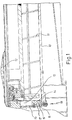
- the screw centrifuge according to the invention has a drum shell 10 with coaxially arranged therein with snail spirals 11 provided screw conveyor, in the same direction of rotation like the centrifuge drum 10, but with a different one Speed rotates.
- the solid-liquid mixture to be dewatered such as B. the sewage sludge is in the centrifuge drum introduced through the central feed pipe 12.
- FIGS. 2 to 4 there is the closure body of the centrifugal valve 18 from a piston valve 19, the after position in Fig. 2 in its bottom dead center and according to Fig. 3 in his top dead center is struck.
- the spool 19 is in a radially inside the drum discharge opening 16 to this blind hole 17 insertable in the drum end wall and in this under the action of the force of a spring 20 and that in the centrifuge mode built-up centrifugal force can be moved back and forth like a piston, having the crossing drum emptying opening 16 according to FIG. 3 releases or closes according to FIG. 2.
- the spring 20 is according to this Embodiment radially in the drum end wall 14 biased arranged outside the drum discharge opening 16 Compression spring, the tension force, which the counterforce to Centrifugal centrifugal force builds up, is matched to the opening speed, in which the valve spool 19 moves radially inward and the drum emptying opening 16 during the shutdown process the centrifuge releases. That is: when parking the Screw centrifuge reduces the speed of the centrifuge drum 10 to a standstill and the centrifugal force is also reduced.
- FIGS. 2 and 3 also show that the piston rod 21 of the piston valve 19 engaging valve spring 20 with its radial outer end in a cap-shaped screw plug 22 is supported, in the end face of the drum end wall 14 from Circumference radially to the centrifuge axis is screwed.
- the radially outer head of this cap-shaped locking screw advantageously has a through hole 23 for liquid discharge and for self-cleaning of the centrifugal valve with self-cleaning of the Coils of the coil spring 20 on.
- the piston slide 19 of the centrifugal valve 18 has both in the lower Dead center (Fig. 2) and in top dead center (Fig. 3) a safe Stop, so that both when closed as A stable valve position even when the valve is open sets.
Landscapes
- Centrifugal Separators (AREA)
Applications Claiming Priority (2)
| Application Number | Priority Date | Filing Date | Title |
|---|---|---|---|
| DE19618249 | 1996-05-07 | ||
| DE19618249A DE19618249A1 (de) | 1996-05-07 | 1996-05-07 | Schneckenzentrifuge mit Fliehkraft-Ventil |
Publications (2)
| Publication Number | Publication Date |
|---|---|
| EP0806245A1 EP0806245A1 (de) | 1997-11-12 |
| EP0806245B1 true EP0806245B1 (de) | 2001-06-06 |
Family
ID=7793552
Family Applications (1)
| Application Number | Title | Priority Date | Filing Date |
|---|---|---|---|
| EP97106703A Expired - Lifetime EP0806245B1 (de) | 1996-05-07 | 1997-04-23 | Schneckenzentrifuge mit Fliehkraft-Ventil |
Country Status (6)
| Country | Link |
|---|---|
| US (1) | US5913767A (ja) |
| EP (1) | EP0806245B1 (ja) |
| JP (1) | JPH11581A (ja) |
| AT (1) | ATE201834T1 (ja) |
| DE (2) | DE19618249A1 (ja) |
| DK (1) | DK0806245T3 (ja) |
Families Citing this family (25)
| Publication number | Priority date | Publication date | Assignee | Title |
|---|---|---|---|---|
| US4650061A (en) * | 1982-07-14 | 1987-03-17 | Weyerhaeuser Company | Crowding lug transfer conveyor system |
| DE10021983A1 (de) * | 2000-05-05 | 2001-11-08 | Baker Hughes De Gmbh | Vollmantelzentrifuge zur Trennung von Feststoff-Flüssigkeitsgemischen |
| US6790169B2 (en) * | 2000-08-31 | 2004-09-14 | Varco I/P, Inc. | Centrifuge with feed tube adapter |
| US6780147B2 (en) * | 2000-08-31 | 2004-08-24 | Varco I/P, Inc. | Centrifuge with open conveyor having an accelerating impeller and flow enhancer |
| US6605029B1 (en) | 2000-08-31 | 2003-08-12 | Tuboscope I/P, Inc. | Centrifuge with open conveyor and methods of use |
| US7018326B2 (en) * | 2000-08-31 | 2006-03-28 | Varco I/P, Inc. | Centrifuge with impellers and beach feed |
| DE50108585D1 (de) | 2000-11-14 | 2006-02-02 | Westfalia Separator Ag | Vollmantel-schneckenzentrifuge mit verteiler |
| DE10065060B4 (de) * | 2000-12-27 | 2004-07-08 | Westfalia Separator Ag | Vollmantel-Schneckenzentrifuge mit Tellereinsatz |
| DE10203652B4 (de) * | 2002-01-30 | 2006-10-19 | Westfalia Separator Ag | Vollmantel-Schneckenzentrifuge mit einem Wehr |
| US20050242003A1 (en) | 2004-04-29 | 2005-11-03 | Eric Scott | Automatic vibratory separator |
| US8172740B2 (en) | 2002-11-06 | 2012-05-08 | National Oilwell Varco L.P. | Controlled centrifuge systems |
| US20060105896A1 (en) * | 2004-04-29 | 2006-05-18 | Smith George E | Controlled centrifuge systems |
| US8312995B2 (en) | 2002-11-06 | 2012-11-20 | National Oilwell Varco, L.P. | Magnetic vibratory screen clamping |
| US7540838B2 (en) * | 2005-10-18 | 2009-06-02 | Varco I/P, Inc. | Centrifuge control in response to viscosity and density parameters of drilling fluid |
| US7540837B2 (en) * | 2005-10-18 | 2009-06-02 | Varco I/P, Inc. | Systems for centrifuge control in response to viscosity and density parameters of drilling fluids |
| US20080083566A1 (en) | 2006-10-04 | 2008-04-10 | George Alexander Burnett | Reclamation of components of wellbore cuttings material |
| US8622220B2 (en) | 2007-08-31 | 2014-01-07 | Varco I/P | Vibratory separators and screens |
| US9073104B2 (en) | 2008-08-14 | 2015-07-07 | National Oilwell Varco, L.P. | Drill cuttings treatment systems |
| US8556083B2 (en) | 2008-10-10 | 2013-10-15 | National Oilwell Varco L.P. | Shale shakers with selective series/parallel flow path conversion |
| US9079222B2 (en) | 2008-10-10 | 2015-07-14 | National Oilwell Varco, L.P. | Shale shaker |
| SE534386C2 (sv) | 2009-10-29 | 2011-08-02 | Alfa Laval Corp Ab | Centrifugalseparator samt metod för separering av fasta partiklar |
| US9643111B2 (en) | 2013-03-08 | 2017-05-09 | National Oilwell Varco, L.P. | Vector maximizing screen |
| DE102014101205B4 (de) * | 2014-01-31 | 2021-08-05 | Flottweg Se | Auslassvorrichtung einer Vollmantelschneckenzentrifuge |
| DE202022100680U1 (de) | 2022-02-07 | 2023-05-11 | Gea Westfalia Separator Group Gmbh | Separator |
| CN116459955A (zh) * | 2023-06-02 | 2023-07-21 | 江苏华大离心机制造有限公司 | 离心分离转鼓及离心分离设备 |
Family Cites Families (7)
| Publication number | Priority date | Publication date | Assignee | Title |
|---|---|---|---|---|
| GB297914A (en) * | 1927-07-26 | 1928-10-04 | Sunderland Forge & Engineering | Improvements in and relating to centrifugal separators |
| US2022815A (en) * | 1933-09-27 | 1935-12-03 | Laval Separator Co De | Centrifugal bowl for separating heavy sludge and solids from lighter liquids |
| GB574667A (en) * | 1943-07-13 | 1946-01-15 | Separator Ab | A centrifugal bowl for separating sludge-containing liquids |
| GB1066541A (en) * | 1962-12-19 | 1967-04-26 | English Electric Co Ltd | Apparatus for supplying electric current from an a.c. supply to a load at a low frequency |
| SE371110B (ja) * | 1973-03-22 | 1974-11-11 | Alfa Laval Ab | |
| AT381718B (de) * | 1982-01-20 | 1986-11-25 | Voest Alpine Ag | Rotierendes spaltsieb zum trocknen von feststoffen, z.b. braunkohlen |
| DE4130759A1 (de) * | 1991-09-16 | 1993-03-18 | Flottweg Gmbh | Zentrifuge zur kontinuierlichen trennung von stoffen unterschiedlicher dichte |
-
1996
- 1996-05-07 DE DE19618249A patent/DE19618249A1/de not_active Withdrawn
-
1997
- 1997-04-23 EP EP97106703A patent/EP0806245B1/de not_active Expired - Lifetime
- 1997-04-23 AT AT97106703T patent/ATE201834T1/de not_active IP Right Cessation
- 1997-04-23 DE DE59703712T patent/DE59703712D1/de not_active Expired - Fee Related
- 1997-04-23 DK DK97106703T patent/DK0806245T3/da active
- 1997-05-07 JP JP9132884A patent/JPH11581A/ja not_active Withdrawn
- 1997-05-07 US US08/852,272 patent/US5913767A/en not_active Expired - Fee Related
Also Published As
| Publication number | Publication date |
|---|---|
| ATE201834T1 (de) | 2001-06-15 |
| US5913767A (en) | 1999-06-22 |
| DE59703712D1 (de) | 2001-07-12 |
| DK0806245T3 (da) | 2001-09-17 |
| DE19618249A1 (de) | 1997-11-13 |
| EP0806245A1 (de) | 1997-11-12 |
| JPH11581A (ja) | 1999-01-06 |
Similar Documents
| Publication | Publication Date | Title |
|---|---|---|
| EP0806245B1 (de) | Schneckenzentrifuge mit Fliehkraft-Ventil | |
| DE3925355C2 (de) | Verfahren und Vorrichtung zum Abscheiden der Einzelkomponenten eines Materialstromes | |
| EP0027630B1 (de) | Zentrifuge zum Trennen von Feststoff-Flüssigkeitsgemischen | |
| DE69306433T2 (de) | Abscheider fester Partikel für den variablen Abzug von Flüssigkeitsströmen in einem zahnärztlichen Apparat | |
| DE69315109T2 (de) | Schneckenzentrifuge mit unterbrochenen Schneckenwendeln im konischen Austragsmantelteil | |
| DE754339C (de) | Verfahren und Vorrichtung zum Entfernen von schweren Teilchen unter Fliehkraftwirkung aus einer Aufschwemmung, insbesondere von Zellstoff, Papierstoff u. dgl. | |
| DE2601528C2 (ja) | ||
| DE60318833T2 (de) | Dekantierzentrifuge | |
| DE2103829A1 (de) | Zentrifuge | |
| DE3344432C2 (de) | Zentrifuge zur Trennung einer Suspension mit zwei getrennt abzuführenden Flüssigkeitsphasen | |
| DE3318793A1 (de) | Vorrichtung zum entfeuchten von schlamm | |
| EP0282956B1 (de) | Fasspumpe | |
| DE69712569T2 (de) | Auslaufvorrichtung und zentrifugalabscheider mit einer solchen auslaufvorrichtung | |
| DE2407653A1 (de) | Zentrifugenpatrone | |
| DE69825261T2 (de) | Zentrifuge mit Mittelachse E | |
| DE3626314A1 (de) | Vorrichtung zum trennen von suspensionen | |
| DE60124554T2 (de) | Zentrifugalabscheider | |
| EP0631820B1 (de) | Verfahren zum Betrieb von Schneckenzentrifugen | |
| DE3132740A1 (de) | Vollmantelzentrifuge mit siebteil | |
| WO1993013865A1 (de) | Vollmantelschneckenzentrifuge | |
| CH374972A (de) | Verfahren und Vorrichtung zum Trennen von Gemischen | |
| DE398102C (de) | Vorrichtung zum Trennen von Gemischen aus festen und fluessigen Bestandteilen, insbesondere von Zuckerkristallen und Mutterlauge | |
| DE2808677A1 (de) | Zentrifuge und trennverfahren | |
| DE155730C (ja) | ||
| DE3636034C1 (en) | Centrifugal drum of a centrifuge for the clarifying and separating of liquid mixtures |
Legal Events
| Date | Code | Title | Description |
|---|---|---|---|
| PUAI | Public reference made under article 153(3) epc to a published international application that has entered the european phase |
Free format text: ORIGINAL CODE: 0009012 |
|
| AK | Designated contracting states |
Kind code of ref document: A1 Designated state(s): AT BE DE DK ES FR GB NL SE |
|
| 17P | Request for examination filed |
Effective date: 19980509 |
|
| RAP1 | Party data changed (applicant data changed or rights of an application transferred) |
Owner name: BAKER HUGHES (DEUTSCHLAND) GMBH |
|
| GRAG | Despatch of communication of intention to grant |
Free format text: ORIGINAL CODE: EPIDOS AGRA |
|
| 17Q | First examination report despatched |
Effective date: 20000512 |
|
| RAP1 | Party data changed (applicant data changed or rights of an application transferred) |
Owner name: BAKER HUGHES (DEUTSCHLAND) GMBH |
|
| GRAG | Despatch of communication of intention to grant |
Free format text: ORIGINAL CODE: EPIDOS AGRA |
|
| GRAH | Despatch of communication of intention to grant a patent |
Free format text: ORIGINAL CODE: EPIDOS IGRA |
|
| GRAH | Despatch of communication of intention to grant a patent |
Free format text: ORIGINAL CODE: EPIDOS IGRA |
|
| GRAA | (expected) grant |
Free format text: ORIGINAL CODE: 0009210 |
|
| AK | Designated contracting states |
Kind code of ref document: B1 Designated state(s): AT BE DE DK ES FR GB NL SE |
|
| REF | Corresponds to: |
Ref document number: 201834 Country of ref document: AT Date of ref document: 20010615 Kind code of ref document: T |
|
| GBT | Gb: translation of ep patent filed (gb section 77(6)(a)/1977) |
Effective date: 20010606 |
|
| REF | Corresponds to: |
Ref document number: 59703712 Country of ref document: DE Date of ref document: 20010712 |
|
| ET | Fr: translation filed | ||
| REG | Reference to a national code |
Ref country code: DK Ref legal event code: T3 |
|
| PG25 | Lapsed in a contracting state [announced via postgrant information from national office to epo] |
Ref country code: ES Free format text: LAPSE BECAUSE OF FAILURE TO SUBMIT A TRANSLATION OF THE DESCRIPTION OR TO PAY THE FEE WITHIN THE PRESCRIBED TIME-LIMIT Effective date: 20011220 |
|
| REG | Reference to a national code |
Ref country code: GB Ref legal event code: IF02 |
|
| PGFP | Annual fee paid to national office [announced via postgrant information from national office to epo] |
Ref country code: NL Payment date: 20020329 Year of fee payment: 6 |
|
| PGFP | Annual fee paid to national office [announced via postgrant information from national office to epo] |
Ref country code: FR Payment date: 20020401 Year of fee payment: 6 |
|
| PGFP | Annual fee paid to national office [announced via postgrant information from national office to epo] |
Ref country code: SE Payment date: 20020403 Year of fee payment: 6 Ref country code: DK Payment date: 20020403 Year of fee payment: 6 |
|
| PLBE | No opposition filed within time limit |
Free format text: ORIGINAL CODE: 0009261 |
|
| STAA | Information on the status of an ep patent application or granted ep patent |
Free format text: STATUS: NO OPPOSITION FILED WITHIN TIME LIMIT |
|
| PGFP | Annual fee paid to national office [announced via postgrant information from national office to epo] |
Ref country code: GB Payment date: 20020417 Year of fee payment: 6 |
|
| PG25 | Lapsed in a contracting state [announced via postgrant information from national office to epo] |
Ref country code: AT Free format text: LAPSE BECAUSE OF NON-PAYMENT OF DUE FEES Effective date: 20020423 |
|
| PG25 | Lapsed in a contracting state [announced via postgrant information from national office to epo] |
Ref country code: BE Free format text: LAPSE BECAUSE OF NON-PAYMENT OF DUE FEES Effective date: 20020430 |
|
| 26N | No opposition filed | ||
| PG25 | Lapsed in a contracting state [announced via postgrant information from national office to epo] |
Ref country code: GB Free format text: LAPSE BECAUSE OF NON-PAYMENT OF DUE FEES Effective date: 20030423 |
|
| PG25 | Lapsed in a contracting state [announced via postgrant information from national office to epo] |
Ref country code: SE Free format text: LAPSE BECAUSE OF NON-PAYMENT OF DUE FEES Effective date: 20030424 |
|
| PG25 | Lapsed in a contracting state [announced via postgrant information from national office to epo] |
Ref country code: DK Free format text: LAPSE BECAUSE OF NON-PAYMENT OF DUE FEES Effective date: 20030430 |
|
| PGFP | Annual fee paid to national office [announced via postgrant information from national office to epo] |
Ref country code: DE Payment date: 20030430 Year of fee payment: 7 |
|
| PG25 | Lapsed in a contracting state [announced via postgrant information from national office to epo] |
Ref country code: NL Free format text: LAPSE BECAUSE OF NON-PAYMENT OF DUE FEES Effective date: 20031101 |
|
| NLV4 | Nl: lapsed or anulled due to non-payment of the annual fee |
Effective date: 20031101 |
|
| EUG | Se: european patent has lapsed | ||
| REG | Reference to a national code |
Ref country code: DK Ref legal event code: EBP |
|
| GBPC | Gb: european patent ceased through non-payment of renewal fee |
Effective date: 20030423 |
|
| PG25 | Lapsed in a contracting state [announced via postgrant information from national office to epo] |
Ref country code: FR Free format text: LAPSE BECAUSE OF NON-PAYMENT OF DUE FEES Effective date: 20031231 |
|
| REG | Reference to a national code |
Ref country code: FR Ref legal event code: ST |
|
| PG25 | Lapsed in a contracting state [announced via postgrant information from national office to epo] |
Ref country code: DE Free format text: LAPSE BECAUSE OF NON-PAYMENT OF DUE FEES Effective date: 20041103 |