EP0806256A2 - Procédé de contrÔle du coulement de matériau pendant l'emboutissage des pièces de tÔle et dispositif pour la mise en oeuvre du procédé - Google Patents
Procédé de contrÔle du coulement de matériau pendant l'emboutissage des pièces de tÔle et dispositif pour la mise en oeuvre du procédé Download PDFInfo
- Publication number
- EP0806256A2 EP0806256A2 EP97107440A EP97107440A EP0806256A2 EP 0806256 A2 EP0806256 A2 EP 0806256A2 EP 97107440 A EP97107440 A EP 97107440A EP 97107440 A EP97107440 A EP 97107440A EP 0806256 A2 EP0806256 A2 EP 0806256A2
- Authority
- EP
- European Patent Office
- Prior art keywords
- hold
- force
- frictional force
- control loop
- sheet metal
- Prior art date
- Legal status (The legal status is an assumption and is not a legal conclusion. Google has not performed a legal analysis and makes no representation as to the accuracy of the status listed.)
- Granted
Links
- 238000000034 method Methods 0.000 title claims abstract description 26
- 239000002184 metal Substances 0.000 title claims description 19
- 239000000463 material Substances 0.000 title claims description 17
- 230000001276 controlling effect Effects 0.000 claims description 6
- 230000001105 regulatory effect Effects 0.000 claims description 6
- 238000000418 atomic force spectrum Methods 0.000 claims description 4
- 238000005457 optimization Methods 0.000 claims 1
- 239000000314 lubricant Substances 0.000 description 5
- 238000005259 measurement Methods 0.000 description 2
- 230000037303 wrinkles Effects 0.000 description 2
- 206010038743 Restlessness Diseases 0.000 description 1
- 239000011324 bead Substances 0.000 description 1
- 238000009530 blood pressure measurement Methods 0.000 description 1
- 238000006243 chemical reaction Methods 0.000 description 1
- 238000010276 construction Methods 0.000 description 1
- 230000001419 dependent effect Effects 0.000 description 1
- 238000006073 displacement reaction Methods 0.000 description 1
- 230000000694 effects Effects 0.000 description 1
- 238000005516 engineering process Methods 0.000 description 1
- 230000001788 irregular Effects 0.000 description 1
- 230000011218 segmentation Effects 0.000 description 1
Images
Classifications
-
- B—PERFORMING OPERATIONS; TRANSPORTING
- B21—MECHANICAL METAL-WORKING WITHOUT ESSENTIALLY REMOVING MATERIAL; PUNCHING METAL
- B21D—WORKING OR PROCESSING OF SHEET METAL OR METAL TUBES, RODS OR PROFILES WITHOUT ESSENTIALLY REMOVING MATERIAL; PUNCHING METAL
- B21D24/00—Special deep-drawing arrangements in, or in connection with, presses
- B21D24/04—Blank holders; Mounting means therefor
- B21D24/08—Pneumatically or hydraulically loaded blank holders
-
- B—PERFORMING OPERATIONS; TRANSPORTING
- B21—MECHANICAL METAL-WORKING WITHOUT ESSENTIALLY REMOVING MATERIAL; PUNCHING METAL
- B21D—WORKING OR PROCESSING OF SHEET METAL OR METAL TUBES, RODS OR PROFILES WITHOUT ESSENTIALLY REMOVING MATERIAL; PUNCHING METAL
- B21D24/00—Special deep-drawing arrangements in, or in connection with, presses
- B21D24/10—Devices controlling or operating blank holders independently, or in conjunction with dies
- B21D24/14—Devices controlling or operating blank holders independently, or in conjunction with dies pneumatically or hydraulically
Definitions
- the invention relates to a method for material flow control when drawing sheet metal parts according to the preamble of claim 1 and a device for performing the method according to the preamble of claim 10.
- the drawing device can also be realized by means of hydraulic or pneumatic cylinders arranged in the drawing tool.
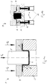
- FIG. 1a shows a double-acting press for drawing regular sheet metal parts.
- the pressing device 1 shows a workpiece 2 (sheet metal) which is clamped between a drawing ring 3 and a hold-down device 4 and is acted upon by a drawing punch 5.
- the punch force is denoted by F S , the hold-down force by F N.
- the workpiece 2 is held on the drawing flange 6 and on the drawing edge 7 in the Drawn part wall 8 (frame) formed.
- the material flow is also influenced by the friction acting between hold-down device 4 and sheet metal 2 or between sheet metal 2 and drawing ring 3.
- FIG. 1b shows the basic structure of a known single-acting press device 9 as a single-acting press with a hydraulic pulling device 10 with hydraulic cylinders 11 and the pulling ring 3, the holding-down device 4 and the pulling die 5 described for FIG. 1a.
- a holding-down force sensor is indicated by reference number 13. This press can also be used to pull irregular sheet metal parts.
- the hydraulic pulling devices 10 consisting of hydraulic cylinders 11 that can be individually controlled via servo valves (not shown in detail), can introduce the hold-down forces F N directly into the hold-down device 4 via the piston rods 12 (see FIG. 1b) or indirectly via sleeves (see, for example, DE 41 12 656 A1).
- hold-down pressure profiles defined before the drawing process are specified via the drawing path in a control loop which realizes the desired holding-down force during the drawing process.
- the disadvantage of these systems is that the predefined hold-down pressure profiles for controlling the material flow are based on constant frictional relationships between hold-down device 4 and plate 2 or between the drawing ring and plate.
- Control loops represent a significant improvement and use forming parameters such as the flange edge inlet, the punch force or the pleat height of the current drawing process as a control variable.
- the punch force F S contains the forces of friction between sheet metal 2 and hold-down device 4 and the friction between drawing ring 3 and hold-down device 4. However, it also includes all other frictional forces and the forming forces, so that they are only of limited use as a control variable for controlling the material flow is. The experience gained with this confirms the criticism of the use of these variables as reference variables for material flow control.
- the invention has for its object to improve the known drawing methods and drawing presses and in particular to enable a more precise recording of the drawing parameters and the associated process flows.
- the frictional force between sheet metal and hold-down device or sheet and drawing ring should be taken into account as a controlled variable.
- FIGS 1a, 1b show the known prior art
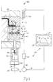
- FIG. 2 shows a schematic illustration of a drawing device according to the invention with a control device, the same parts being identified with the same reference numerals as possible with respect to FIGS. 1a, 1b, as far as possible.
- a control circuit 21 is used for material flow control, which, using the hold-down force F N as manipulated variable 22 of the hold-down force F N, allows the friction acting on the surface 23 of the hold-down device and / or the drawing ring 3 to regulate according to a predetermined command variable 24 (friction force F R over the drawing path s) (FIG. 2).
- the friction force F R is therefore measured via a friction force sensor 25, 25 ′, 25 ′′, which is preferably designed as a three-component piezo force measuring element 26, ie based on a piezoelectric effect.
- Such sensors 25 ', 25'' can in particular also be installed at predetermined locations on the hold-down device 4 and / or also on the drawing ring 3 (see dashed lines in FIG. 2).
- the control loop shown in FIG. 2 reacts automatically to the changes in the tribological system 40, ie it controls automatically the changes in the friction force measured with the friction force sensor 25, which are caused, for example, by changes in the amount of lubricant and the type of lubricant, the sheet surface, etc.
- a press or tool device 20 is required which allows the hold-down force 30 to be changed during the drawing process. This is possible when using hydraulic die cushions in the table of single-acting presses, as is also shown in principle in FIG. 1b.
- a preferably segmented hold-down device 4 with upper segment 27 and lower segment 28 are each acted upon by their own hydraulic cylinder 11 arranged in the press 20 or possibly also in the tool, wherein each cylinder 11 can be actuated via its own servo valve 29.
- the servo valve 29 controls the oil flow and thus determines the pressure acting in the cylinder 11 and thus the hold-down force 30 prevailing at the segment 27. This can be determined both by a pressure measurement in the cylinder 11 or by a hold-down force sensor 25, 26 arranged in the force flow.
- the segment is therefore supported by three-component piezo force measuring elements 26. These allow the measurement of a frictional force 25 'and the hold-down force 30 acting on the segment 27. If necessary, only one frictional force sensor can also be introduced into the hold-down device of the drawing tool. A segmentation of the hold-down device can possibly be omitted if the design is correspondingly "soft" and elastic.
- the friction force sensor in corner areas in which folds are to be suppressed can be coupled with a fold height sensor known from the literature, so that it is always ensured that the hold-down force is at least so great that folds in the flange are reliably avoided.
- a computer 31 with an analog / digital interface is used as the control unit.
- the desired curve 32 of the frictional force can be stored as a guide variable 24 via the tappet path.
- the assigned value of the frictional force can be read out from this control unit 31. This is given to controller 35 as setpoint 36.
- controller 35 With the help of the friction force sensor 25 and the downstream amplifier 37, the associated actual value of the friction force can be given to the second input of the controller 35. If the controller determines a difference between setpoint 36 and actual value 38, it generates an actuating signal 39 which is fed to an actuator (servo valve 29) of the hydraulic circuit of the segment. The signal influences the control element in such a way that the actual value of the frictional force changes so that the difference between actual value 38 and setpoint 36 is minimized.
- the control loop according to the invention accordingly reacts independently to changes in the friction between the hold-down device and the sheet metal and between the drawing ring and sheet metal, caused by changes in the type or amount of lubricant on the sheet metal, changes in the sheet metal surface and by tool lock or the like (tribological properties).
Landscapes
- Engineering & Computer Science (AREA)
- Mechanical Engineering (AREA)
- Shaping Metal By Deep-Drawing, Or The Like (AREA)
- Forging (AREA)
Applications Claiming Priority (2)
| Application Number | Priority Date | Filing Date | Title |
|---|---|---|---|
| DE19617965 | 1996-05-06 | ||
| DE19617965 | 1996-05-06 |
Publications (3)
| Publication Number | Publication Date |
|---|---|
| EP0806256A2 true EP0806256A2 (fr) | 1997-11-12 |
| EP0806256A3 EP0806256A3 (fr) | 1998-01-21 |
| EP0806256B1 EP0806256B1 (fr) | 1999-11-10 |
Family
ID=7793355
Family Applications (1)
| Application Number | Title | Priority Date | Filing Date |
|---|---|---|---|
| EP97107440A Expired - Lifetime EP0806256B1 (fr) | 1996-05-06 | 1997-05-06 | Procédé de contrÔle du coulement de matériau pendant l'emboutissage des pièces de tÔle et dispositif pour la mise en oeuvre du procédé |
Country Status (2)
| Country | Link |
|---|---|
| EP (1) | EP0806256B1 (fr) |
| DE (2) | DE19718841A1 (fr) |
Cited By (4)
| Publication number | Priority date | Publication date | Assignee | Title |
|---|---|---|---|---|
| EP0974410A3 (fr) * | 1998-07-17 | 2003-04-23 | EP Technology AB | Dispositif à contrôle hydraulique pour élément de tenue à contrepression |
| WO2004009263A1 (fr) * | 2002-07-20 | 2004-01-29 | Nothelfer Gmbh | Procede de gestion du flux de matieres lors d'un processus d'emboutissage de toles et outil d'emboutissage |
| NL1021738C2 (nl) * | 2002-10-24 | 2004-04-27 | Tno | Werkwijze en inrichting voor het reduceren van plooivorming bij dieptrekken. |
| US10786842B2 (en) | 2018-09-12 | 2020-09-29 | Fca Us Llc | Draw-in control for sheet drawing |
Families Citing this family (4)
| Publication number | Priority date | Publication date | Assignee | Title |
|---|---|---|---|---|
| DE10210573A1 (de) * | 2002-03-11 | 2003-10-02 | Dieffenbacher Gmbh Maschf | Hydroelastische Tiefzieheinrichtung |
| DE10329898B4 (de) * | 2003-07-03 | 2006-09-28 | Thyssenkrupp Steel Ag | Verfahren und Vorrichtung zum Umformen von Blechplatinen |
| DE10331939B4 (de) * | 2003-07-15 | 2014-09-18 | Bayerische Motoren Werke Aktiengesellschaft | Blechumformwerkzeug |
| DE102004059141A1 (de) * | 2004-12-08 | 2006-06-14 | Wieber, Christian, Dipl.-Ing.(FH), Batu Caves | Hydraulische Presse |
Family Cites Families (1)
| Publication number | Priority date | Publication date | Assignee | Title |
|---|---|---|---|---|
| DE4338828C2 (de) * | 1993-11-13 | 1996-01-25 | Daimler Benz Ag | Verfahren zum Betreiben von Ziehpressen sowie hierzu geeignete Ziehpresse |
-
1997
- 1997-05-06 DE DE19718841A patent/DE19718841A1/de not_active Withdrawn
- 1997-05-06 EP EP97107440A patent/EP0806256B1/fr not_active Expired - Lifetime
- 1997-05-06 DE DE59700677T patent/DE59700677D1/de not_active Expired - Lifetime
Cited By (6)
| Publication number | Priority date | Publication date | Assignee | Title |
|---|---|---|---|---|
| EP0974410A3 (fr) * | 1998-07-17 | 2003-04-23 | EP Technology AB | Dispositif à contrôle hydraulique pour élément de tenue à contrepression |
| WO2004009263A1 (fr) * | 2002-07-20 | 2004-01-29 | Nothelfer Gmbh | Procede de gestion du flux de matieres lors d'un processus d'emboutissage de toles et outil d'emboutissage |
| US7086265B2 (en) | 2002-07-20 | 2006-08-08 | Nothelfer Gmbh | Method for controlling the material flow during the deep-drawings of sheet metal, and deep-drawing tool |
| NL1021738C2 (nl) * | 2002-10-24 | 2004-04-27 | Tno | Werkwijze en inrichting voor het reduceren van plooivorming bij dieptrekken. |
| WO2004037460A1 (fr) * | 2002-10-24 | 2004-05-06 | Nederlandse Organisatie Voor Toegepast-Natuurwe Tenschappelijk Onderzoek Tno | Procede et appareil pour reduire la formation de plis dans une operation d'emboutissage profond |
| US10786842B2 (en) | 2018-09-12 | 2020-09-29 | Fca Us Llc | Draw-in control for sheet drawing |
Also Published As
| Publication number | Publication date |
|---|---|
| EP0806256A3 (fr) | 1998-01-21 |
| DE59700677D1 (de) | 1999-12-16 |
| EP0806256B1 (fr) | 1999-11-10 |
| DE19718841A1 (de) | 1997-11-13 |
Similar Documents
| Publication | Publication Date | Title |
|---|---|---|
| DE3840395C2 (de) | Steuerung einer Blechbearbeitungspresse | |
| DE69102744T2 (de) | Vorrichtung zur Kraftregulierung der Niederhalter einer Presse. | |
| EP2105280B1 (fr) | Procédé d'utilisation d'un outil de soudure par ultrasons doté d'un entraînement fluidique | |
| DE3600364C2 (fr) | ||
| DE4242442C2 (de) | Verfahren zum Einstellen der Klemmkraft des Niederhalters von Ziehpressen | |
| DE69321360T2 (de) | Durchbruchpuffer fur pressen und steuerverfahren dafur | |
| DE102004012294B4 (de) | Hochgeschwindigkeitsantriebsverfahren und -system für Druckzylinder | |
| EP0585589B1 (fr) | Procédé pour l'optimisation de processus d'emboutissage automatique et itératif aux presses | |
| DE3744177C2 (fr) | ||
| EP0205054A2 (fr) | Dispositif de commande de la pression de travail sur des machines de rodage, de honage ou de polissage | |
| EP0806256B1 (fr) | Procédé de contrÔle du coulement de matériau pendant l'emboutissage des pièces de tÔle et dispositif pour la mise en oeuvre du procédé | |
| DE19954310B4 (de) | Verfahren zum schnellen Regeln von Ziehvorgängen in Pressen und hierzu geeignete Ziehpresse | |
| DE102017114596A1 (de) | Verfahren und Einrichtung zur Regelung des Tiefziehprozesses während des Pressenhubes | |
| DE102006031438B4 (de) | Vorrichtung zum Umformen von Platinen | |
| DE69703964T2 (de) | Verbesserung zu dem niederhaltedruckregulierungssystem in pressen | |
| DE4338828C2 (de) | Verfahren zum Betreiben von Ziehpressen sowie hierzu geeignete Ziehpresse | |
| DE102018217337A1 (de) | Bewegungsvorrichtung, Reifenhandhabungsvorrichtung und Verfahren zum Betrieb eines fluidischen Aktors | |
| EP2001615B1 (fr) | Procédé et dispositif de pliage de pièces métalliques plates | |
| EP0673695B1 (fr) | Procédé et arrangement de réglage pour interrompre et continuer l'emboutissage à presses à deux étages, en particulier à presses hydrauliques | |
| EP1625901A1 (fr) | Presse avec dispositif de détection de la position de référence mutuelle des parties d' outils d' un outil de presse | |
| DE4343336B4 (de) | Hydraulische Tiefzieheinrichtung | |
| EP0417753B1 (fr) | Presse mécanique ou hydraulique avec dispositif d'étirage ou d'emboutissage pour presse à plusieurs étapes | |
| EP0284903B1 (fr) | Presse à piston | |
| EP0703018A1 (fr) | Presse mécanique ou hydraulique | |
| DE3136753C2 (de) | Tiefzieheinrichtung für Platine |
Legal Events
| Date | Code | Title | Description |
|---|---|---|---|
| PUAI | Public reference made under article 153(3) epc to a published international application that has entered the european phase |
Free format text: ORIGINAL CODE: 0009012 |
|
| AK | Designated contracting states |
Kind code of ref document: A2 Designated state(s): DE FR IT |
|
| PUAL | Search report despatched |
Free format text: ORIGINAL CODE: 0009013 |
|
| AK | Designated contracting states |
Kind code of ref document: A3 Designated state(s): DE FR IT |
|
| 17P | Request for examination filed |
Effective date: 19980605 |
|
| GRAG | Despatch of communication of intention to grant |
Free format text: ORIGINAL CODE: EPIDOS AGRA |
|
| GRAG | Despatch of communication of intention to grant |
Free format text: ORIGINAL CODE: EPIDOS AGRA |
|
| GRAH | Despatch of communication of intention to grant a patent |
Free format text: ORIGINAL CODE: EPIDOS IGRA |
|
| 17Q | First examination report despatched |
Effective date: 19990210 |
|
| GRAH | Despatch of communication of intention to grant a patent |
Free format text: ORIGINAL CODE: EPIDOS IGRA |
|
| GRAA | (expected) grant |
Free format text: ORIGINAL CODE: 0009210 |
|
| AK | Designated contracting states |
Kind code of ref document: B1 Designated state(s): DE FR IT |
|
| REF | Corresponds to: |
Ref document number: 59700677 Country of ref document: DE Date of ref document: 19991216 |
|
| ET | Fr: translation filed | ||
| ITF | It: translation for a ep patent filed | ||
| PLBE | No opposition filed within time limit |
Free format text: ORIGINAL CODE: 0009261 |
|
| STAA | Information on the status of an ep patent application or granted ep patent |
Free format text: STATUS: NO OPPOSITION FILED WITHIN TIME LIMIT |
|
| 26N | No opposition filed | ||
| PGFP | Annual fee paid to national office [announced via postgrant information from national office to epo] |
Ref country code: IT Payment date: 20090527 Year of fee payment: 13 |
|
| REG | Reference to a national code |
Ref country code: FR Ref legal event code: ST Effective date: 20100129 |
|
| PG25 | Lapsed in a contracting state [announced via postgrant information from national office to epo] |
Ref country code: FR Free format text: LAPSE BECAUSE OF NON-PAYMENT OF DUE FEES Effective date: 20090602 |
|
| PGFP | Annual fee paid to national office [announced via postgrant information from national office to epo] |
Ref country code: FR Payment date: 20080519 Year of fee payment: 12 |
|
| REG | Reference to a national code |
Ref country code: FR Ref legal event code: D3 |
|
| PG25 | Lapsed in a contracting state [announced via postgrant information from national office to epo] |
Ref country code: IT Free format text: LAPSE BECAUSE OF NON-PAYMENT OF DUE FEES Effective date: 20100506 |
|
| PGFP | Annual fee paid to national office [announced via postgrant information from national office to epo] |
Ref country code: DE Payment date: 20120522 Year of fee payment: 16 |
|
| PG25 | Lapsed in a contracting state [announced via postgrant information from national office to epo] |
Ref country code: DE Free format text: LAPSE BECAUSE OF NON-PAYMENT OF DUE FEES Effective date: 20131203 |
|
| REG | Reference to a national code |
Ref country code: DE Ref legal event code: R119 Ref document number: 59700677 Country of ref document: DE Effective date: 20131203 |