EP0806290A2 - Vorrichtung zum Formen von Behältern aus wärmeschweissbarem Material - Google Patents
Vorrichtung zum Formen von Behältern aus wärmeschweissbarem Material Download PDFInfo
- Publication number
- EP0806290A2 EP0806290A2 EP97500084A EP97500084A EP0806290A2 EP 0806290 A2 EP0806290 A2 EP 0806290A2 EP 97500084 A EP97500084 A EP 97500084A EP 97500084 A EP97500084 A EP 97500084A EP 0806290 A2 EP0806290 A2 EP 0806290A2
- Authority
- EP
- European Patent Office
- Prior art keywords
- machine
- former
- previous
- boxes
- box
- Prior art date
- Legal status (The legal status is an assumption and is not a legal conclusion. Google has not performed a legal analysis and makes no representation as to the accuracy of the status listed.)
- Granted
Links
Images



Classifications
-
- B—PERFORMING OPERATIONS; TRANSPORTING
- B31—MAKING ARTICLES OF PAPER, CARDBOARD OR MATERIAL WORKED IN A MANNER ANALOGOUS TO PAPER; WORKING PAPER, CARDBOARD OR MATERIAL WORKED IN A MANNER ANALOGOUS TO PAPER
- B31B—MAKING CONTAINERS OF PAPER, CARDBOARD OR MATERIAL WORKED IN A MANNER ANALOGOUS TO PAPER
- B31B50/00—Making rigid or semi-rigid containers, e.g. boxes or cartons
-
- B—PERFORMING OPERATIONS; TRANSPORTING
- B31—MAKING ARTICLES OF PAPER, CARDBOARD OR MATERIAL WORKED IN A MANNER ANALOGOUS TO PAPER; WORKING PAPER, CARDBOARD OR MATERIAL WORKED IN A MANNER ANALOGOUS TO PAPER
- B31B—MAKING CONTAINERS OF PAPER, CARDBOARD OR MATERIAL WORKED IN A MANNER ANALOGOUS TO PAPER
- B31B50/00—Making rigid or semi-rigid containers, e.g. boxes or cartons
- B31B50/59—Shaping sheet material under pressure
- B31B50/592—Shaping sheet material under pressure using punches or dies
-
- B—PERFORMING OPERATIONS; TRANSPORTING
- B31—MAKING ARTICLES OF PAPER, CARDBOARD OR MATERIAL WORKED IN A MANNER ANALOGOUS TO PAPER; WORKING PAPER, CARDBOARD OR MATERIAL WORKED IN A MANNER ANALOGOUS TO PAPER
- B31B—MAKING CONTAINERS OF PAPER, CARDBOARD OR MATERIAL WORKED IN A MANNER ANALOGOUS TO PAPER
- B31B50/00—Making rigid or semi-rigid containers, e.g. boxes or cartons
- B31B50/26—Folding sheets, blanks or webs
- B31B50/44—Folding sheets, blanks or webs by plungers moving through folding dies
-
- B—PERFORMING OPERATIONS; TRANSPORTING
- B31—MAKING ARTICLES OF PAPER, CARDBOARD OR MATERIAL WORKED IN A MANNER ANALOGOUS TO PAPER; WORKING PAPER, CARDBOARD OR MATERIAL WORKED IN A MANNER ANALOGOUS TO PAPER
- B31B—MAKING CONTAINERS OF PAPER, CARDBOARD OR MATERIAL WORKED IN A MANNER ANALOGOUS TO PAPER
- B31B50/00—Making rigid or semi-rigid containers, e.g. boxes or cartons
- B31B50/26—Folding sheets, blanks or webs
- B31B50/44—Folding sheets, blanks or webs by plungers moving through folding dies
- B31B50/46—Folding sheets, blanks or webs by plungers moving through folding dies and interconnecting side walls
-
- B—PERFORMING OPERATIONS; TRANSPORTING
- B31—MAKING ARTICLES OF PAPER, CARDBOARD OR MATERIAL WORKED IN A MANNER ANALOGOUS TO PAPER; WORKING PAPER, CARDBOARD OR MATERIAL WORKED IN A MANNER ANALOGOUS TO PAPER
- B31B—MAKING CONTAINERS OF PAPER, CARDBOARD OR MATERIAL WORKED IN A MANNER ANALOGOUS TO PAPER
- B31B50/00—Making rigid or semi-rigid containers, e.g. boxes or cartons
- B31B50/60—Uniting opposed surfaces or edges; Taping
Definitions
- This invention refers, as its title indicates, to a machine for shaping boxes from sheets or plates of heat-weldable material, whose configuration exactly corresponds to the development of the box or, in other words, with the unfolded box.
- This machnine includes means for supply of the unfolded boxes, means of transport picking up the unfolded boxes from the supply unit, then locating them in a heating unit; means for immobilizing the unfolded boxes in the heating unit, a box former, a treader-former which introduces the unfolded box in the former, hence obtaining the folding of its sides with respect to the base; means of pressing which determines the heat-welding of the opposite ends of the adjoining sides of the shaped box, previously heated in the heating unit and means to remove the shaped boxes by the machine.
- the machine described in this invention includes means of supply of the unfolded boxes; means of transport picking up the boxes from the supply unit, and then locating them in a heating unit; means of immobilizing the unfolded boxes in one heating unit to prevent their immobilization during the heating phase, a box former, a reader-former introducing the unfolded box in the former, obtaining the folding of the sides with respect to the base, means of pressing which determines the heat-welding of the opposite ends of the adjoining sides of the shaped box and means to remove the shaped box by the machine.
- the means of supplying the unfolded boxes consists of a lifting platform, over which the unfolded boxes are piled; above said means of supply, the mentioned transport means are arranged, consisting of a horizontal motorized displacement carriage over which is assembled a pneumatic cylinder which vertically displaces an arm equipped with a pneumatically activated suction pad to hold the unfolded boxes from the supplier to the heating unit.
- This heating unit includes coplanary plates, over which the transporter places the unfolded boxes, the latter being supported on the plates by means of which will be their sides, such that the box base arranged in said unit does not lean over any surface.
- Some displaceable heaters are arranged in this heating unit which heat the opposite ends of the adjoining sides of the boxes by means of the projection over the same of hot air; this heaters are equipped with nozzles defining a flat square-shaped outlet, through which the hot air emerges, permitting that each one of them simultaneous heat the opposite ends of two of the adjoining sides of the box to be shaped.
- This heating will later allow the heat-welding of the ends of the adjoining sides of the box to be performed as it is made of heat-weldable material.
- one machine includes means of immobilization consisting of some treaders, activated by pneumatic cylinders assembled over an upper fixed bridge and which vertically pressed the sides of the unfolded box against the coplanary plates included in the heating unit.
- the former includes some side walls having a cap between them of dimensions slightly higher than the size of the box to be shaped, said shaper being arranged at the lower area of the heating unit.
- the shaper walls have in their lower part some windows through which emerge, towards the central gap, some concealable stops defining, as a whole, a coplanary surface, perpendicular to the walls of the shaper.
- the side walls of the shaper are extended at their upper end in some diverging ramps destined to collaborate in the folding of the sides of the box with respect to its base.
- the treader-former includes two side walls joined together by a lower base of less length than the former and by two upper crossbars, fixed at their ends, the set defining the treader-former a width equal to the inside width of the box to be shaped.
- This treader-former includes between the side walls two ending wedges, arranged perpendicularly to the former and fixed to them with the possibility of rotation; said bending wedges being activated by two pneumatic cylinders arranged inside the treader-former and which arranges them in an open or closed position.
- the invention considers that the bending wedges have at their free end two chamfers set against each other which define a right-angled rim.
- This treader-former is fixed to a pneumatic cylinder obliging it to describe alternative vertical motions, passing from the upper area of the heating unit to the interior of the former and viceversa; the base of the treader-former is aligned vertically with the inner gap of the former, such that on vertically descending, the base of the treader-former presses the base of the box, still unfolded, and introduces it in the former, the ramps defined in its sides, determining the folding of the box, until it reaches a position perpendicular to its base, said perpendicular position being achieved when the box is totally introduced inside the former.
- This limit position is determined by the contact of the base of the box against The concealable stops which during this operation are in a protruding position.
- the bending wedges are open and press to of the lower edges of the box against the concealable stops arranged on two of the opposite sides of the former, obliging the sides of the box to define a right angle with the base.
- the invention contemplates that the machine includes in the corners of the former means of pressing, consisting of tightening clamps which, on gripping the opposite ends of the opposite sides of the adjoining sides of the shaped box, determine their heat-welding thanks to the heating previously made.
- the gripping clamps are provided with gripping devices having a length equal or slightly greater than the height of the boxes to be shaped, said gripping devices being able to have flat profiles or profiles with alternating recesses and salients.
- the invention considers the possibility that the former have an internal conduit for cooling liquid to pass, said conduit defining in the gripping device an inlet and an outlet for connection thereof to the corresponding outside cooling circuit.
- the opening and closing of the clamps is determined by some pneumatic cylinders which act over them.
- the means of removing the boxes, once shaped and heat-welded consist of a motorized conveyor belt, arranged beneath the former, the finished boxes falling over it due to the concealment of the concealable stops of the former.
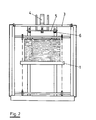
- the machine object of this invention presents means of supply of the unfolded boxes, consisting of a lifting platform (1), over which the unfolded boxes are piled (2).
- some means of transport of the unfolded boxes (2) are arranged consisting of a motorized carriage (3), permitting displacement in a horizontal direction, and over which, is installed a pneumatic cylinder (4) causing the vertical displacement of an arm (5) equipped a suction pad (6) activated pneumatically, and which hold the unfolded boxes (2) during their transport.
- the carriage (3) picks up the boxes one by one from the platform (1) and transports them to the heating unit placing them on coplanary plates (7) where they are supported with what will be the sides of the box.
- this heating unit includes some heaters (8) that may be placed mear or far away from the opposite ends of the adjoining sides of the box by the action by some lower cylinders (9).
- the mission of these heaters (8) is to project hot air over the opposite ends of the adjoining sides of the unfolded boxes, being equipped with nozzles (10) defining a flat right angled outlet, which permits them to simultaneously heat said opposite ends of the adjoining sides of the box to be shaped.
- the machine includes means of immobilizing them, consisting of some treaders (11) which are activated by pneumatic cylinders (12) installed over a fixed upper bridge (13).
- the treaders (11) vertically press the sides of the unfolded box against the coplanary plates (7) include in the heating unit.
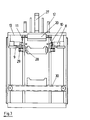
- the box former is arranged, shown in the figure as (14) and including side walls (15) which define a gap between them having dimensions slightly higher than that of the box to be shaped.
- the walls (15) of the shaper define in their lower area some windows (16) through which emerges, towards the central gap, some concealable stops (17).
- the set of concealable stops (7) defines a coplanary surface, perpendicular to the walls (15) of the shaper.
- the concealable stops (17) are assembled with the possibility of rotation over the back sides of the walls (15), the concealable stops (15) being activated, installed over each one of the walls (15), by a pneumatic cylinder (18) determining their arrangement in a hidden or protruding position with respect to the corresponding walls (15).
- the side walls (15) of the shaper (14) are extended at their upper end in some diverging ramps (19) destined to collaborate in the folding of the unfolded boxes (2) when they are displaced towards the interior of the former by a treader-former, shown as a whole as (20) in figure 3.
- the treader-former 20 consists of two side walls 21) which are joined to each other by a lower base (22) of less length that the former and by two upper cross bars (23), fixed at their ends, the treader-former having a width equal to the inside width of the box to be shaped.
- the treader-former (20) includes between the side walls 21) two bending wedges (24) arranged perpendicular to the former and fixed to them with the possibility of rotation by means of the respective axles (25).
- the bending wedges may be arranged in an open or closed position due to the action of two pneumatic cylinders (26) over them and have at their free end two chamfers set against each other which define a right angle.
- the treader-former (20) is fed to a pneumatic cylinder (27) fitted over the upper fixed bridge (13).
- the pneumatic cylinder (27) transmit to the treader-former an alternative vertical motion, displacing it from the upper area of the heating unit to the inside of the former and viceversa.
- the base of the treader-former (20) is aligned vertically with the interior gap of the former (14), and in its vertical descent acts over the base of the box (2) arranged in the heating unit and over which the heaters (8) have previously acted, projecting hot air over the opposite ends of the adjoining sides of the box to be shaped; in this descent, the treader-former (20) induces the introduction of the box inside the former (14), bending its sides with respect to the base, first of all by the action of the ramps (19) over them and secondly, by the action of the sides (15) of the former over said sides.
- the treader-former (20) provokes the descent of the box to be shaped until it makes contact with the concealable stops (17) when the bending wedges (24) open to activate with their ends, against the edges defined by the base of the box and two of its sides, this moment corresponding with that representing in figure 6.
- the machine For the sides of the shaped box to be kept in a position perpendicular to the base thereof, the machine includes in the corners of the former (14), some means of pressing, consisting of tightening clamps (28) which are activated by pneumatic cylinders (29); these clamps (28) press the opposite ends of the adjoining sides of the box which are still hot, determining their heat-welding, by which the box is definitely shaped.
- the bending wedges (24) pass to the closing position and the treader-former set is displaced towards the upper area, by the action of the cylinder (27); simultaneously the concealable stops (17) are concealed in the walls (15) and the finished box falls under its own weight towards means for removal, consisting of motorized transport means (30), responsible for removing the boxes from the machines.
Landscapes
- Making Paper Articles (AREA)
- Lining Or Joining Of Plastics Or The Like (AREA)
- Laminated Bodies (AREA)
Priority Applications (1)
| Application Number | Priority Date | Filing Date | Title |
|---|---|---|---|
| EP01119324A EP1175996B1 (de) | 1996-05-09 | 1997-05-08 | Vorrichtung zum Formen von Behältern aus wärmeschweissbarem Material |
Applications Claiming Priority (2)
| Application Number | Priority Date | Filing Date | Title |
|---|---|---|---|
| ES9601041 | 1996-05-09 | ||
| ES009601041A ES2131442B1 (es) | 1996-05-09 | 1996-05-09 | Maquina para conformar cajas de material termosoldable. |
Related Child Applications (1)
| Application Number | Title | Priority Date | Filing Date |
|---|---|---|---|
| EP01119324A Division EP1175996B1 (de) | 1996-05-09 | 1997-05-08 | Vorrichtung zum Formen von Behältern aus wärmeschweissbarem Material |
Publications (3)
| Publication Number | Publication Date |
|---|---|
| EP0806290A2 true EP0806290A2 (de) | 1997-11-12 |
| EP0806290A3 EP0806290A3 (de) | 1999-05-12 |
| EP0806290B1 EP0806290B1 (de) | 2002-08-14 |
Family
ID=8294760
Family Applications (2)
| Application Number | Title | Priority Date | Filing Date |
|---|---|---|---|
| EP97500084A Expired - Lifetime EP0806290B1 (de) | 1996-05-09 | 1997-05-08 | Vorrichtung zum Formen von Behältern aus wärmeschweissbarem Material |
| EP01119324A Expired - Lifetime EP1175996B1 (de) | 1996-05-09 | 1997-05-08 | Vorrichtung zum Formen von Behältern aus wärmeschweissbarem Material |
Family Applications After (1)
| Application Number | Title | Priority Date | Filing Date |
|---|---|---|---|
| EP01119324A Expired - Lifetime EP1175996B1 (de) | 1996-05-09 | 1997-05-08 | Vorrichtung zum Formen von Behältern aus wärmeschweissbarem Material |
Country Status (4)
| Country | Link |
|---|---|
| EP (2) | EP0806290B1 (de) |
| AT (1) | ATE222177T1 (de) |
| DE (1) | DE69714641D1 (de) |
| ES (1) | ES2131442B1 (de) |
Cited By (3)
| Publication number | Priority date | Publication date | Assignee | Title |
|---|---|---|---|---|
| CN105290799A (zh) * | 2015-11-27 | 2016-02-03 | 东莞市欣桂实业有限公司 | 一种自动点胶折合成型设备及其生产工艺 |
| CN110126345A (zh) * | 2019-05-16 | 2019-08-16 | 中山市美易达包装有限公司 | 一种高效智能纸盒折叠装置 |
| CN118596543A (zh) * | 2024-05-07 | 2024-09-06 | 浙江天能电池(江苏)有限公司 | 一种蓄电池表面加热装置 |
Families Citing this family (3)
| Publication number | Priority date | Publication date | Assignee | Title |
|---|---|---|---|---|
| ES2177470B1 (es) * | 2001-05-18 | 2004-09-01 | Tecnicart Aplicacions Tecniques Del Cartro, S.L. | Maquina para la fabricacion de cajas de carton. |
| ITMI20052218A1 (it) * | 2005-11-18 | 2007-05-19 | Bini Meccanica S R L | Apparecchiatura per la formatura di vassoi borsati a partire da fogli fustellati |
| ES2523902B1 (es) * | 2013-05-31 | 2015-09-08 | Telesforo González Olmos | Máquina formadora de cajas y/o tapas de material laminar |
Family Cites Families (6)
| Publication number | Priority date | Publication date | Assignee | Title |
|---|---|---|---|---|
| GB900118A (en) * | 1958-08-11 | 1962-07-04 | John Cleland & Son Ltd | Improvements in or relating to apparatus for forming cartons |
| US3602108A (en) * | 1969-08-14 | 1971-08-31 | Container Corp | Apparatus for forming container body |
| US4936815A (en) * | 1988-04-18 | 1990-06-26 | Liberty Diversified Industries | Tray forming machine |
| NO900059L (no) * | 1990-01-05 | 1991-07-08 | Norsk Hydro As | Utstyr for folding og sammenfoeyning av kasser som dannes av flate eller hovedsakelig flate kasseemner. |
| ES2024243A6 (es) * | 1990-05-10 | 1992-02-16 | Embalaje Iberoamericana | Perfeccionamientos en maquinas conformadoras de contenedores. |
| ES2066669B1 (es) * | 1992-07-16 | 1995-10-16 | Boix Maquinaria Sa | Mejoras introducidas en moldes para la formacion de cajas de carton. |
-
1996
- 1996-05-09 ES ES009601041A patent/ES2131442B1/es not_active Expired - Fee Related
-
1997
- 1997-05-08 AT AT97500084T patent/ATE222177T1/de not_active IP Right Cessation
- 1997-05-08 EP EP97500084A patent/EP0806290B1/de not_active Expired - Lifetime
- 1997-05-08 EP EP01119324A patent/EP1175996B1/de not_active Expired - Lifetime
- 1997-05-08 DE DE69714641T patent/DE69714641D1/de not_active Expired - Lifetime
Cited By (3)
| Publication number | Priority date | Publication date | Assignee | Title |
|---|---|---|---|---|
| CN105290799A (zh) * | 2015-11-27 | 2016-02-03 | 东莞市欣桂实业有限公司 | 一种自动点胶折合成型设备及其生产工艺 |
| CN110126345A (zh) * | 2019-05-16 | 2019-08-16 | 中山市美易达包装有限公司 | 一种高效智能纸盒折叠装置 |
| CN118596543A (zh) * | 2024-05-07 | 2024-09-06 | 浙江天能电池(江苏)有限公司 | 一种蓄电池表面加热装置 |
Also Published As
| Publication number | Publication date |
|---|---|
| EP1175996A2 (de) | 2002-01-30 |
| EP1175996A3 (de) | 2002-06-12 |
| DE69714641D1 (de) | 2002-09-19 |
| ES2131442B1 (es) | 2000-01-16 |
| EP0806290B1 (de) | 2002-08-14 |
| ATE222177T1 (de) | 2002-08-15 |
| EP0806290A3 (de) | 1999-05-12 |
| EP1175996B1 (de) | 2003-08-13 |
| ES2131442A1 (es) | 1999-07-16 |
Similar Documents
| Publication | Publication Date | Title |
|---|---|---|
| US4757666A (en) | Apparatus for folding and closing a blank of wrapping material around an article to be packaged | |
| US6324818B1 (en) | Vacuum filling machine for bags | |
| CN113665874B (zh) | 一种袋装产品自动包装系统及包装方法 | |
| EP0806290B1 (de) | Vorrichtung zum Formen von Behältern aus wärmeschweissbarem Material | |
| JPH1170600A (ja) | 箱状容器の底部に熱収縮性プラスチックフィルムを自動的に糊付けする方法と装置 | |
| CN107640377B (zh) | 一种样品布自动化包装线 | |
| CN111377078B (zh) | 一种图书包装机 | |
| JP7842468B2 (ja) | 段ボール箱の成形印刷機械 | |
| KR102313204B1 (ko) | 제함기의 포장박스 밴딩장치 | |
| EP1188542B1 (de) | Maschine und Verfahren zum Herstellen von Behältern aus, von einer Wickelrolle kommenden, bahnförmigen Material | |
| KR100231004B1 (ko) | 포장박스 자동공급장치 | |
| US5890344A (en) | Flexible product folding and transferring apparatus and process | |
| US5147270A (en) | Equipment for folding and joining boxes made from flat or basically flat materials | |
| JPS62260629A (ja) | 平坦な管状包装容器空包の盛上げ装置 | |
| US6575219B1 (en) | Method and device for interlocking stackwise plastic bags, especially bags for automatic machines, by welding | |
| CN218967371U (zh) | 一种熟食食品全自动包装热封装置 | |
| CN224130596U (zh) | 一种纸盒封口机 | |
| JPH0718564Y2 (ja) | 容器成形充填装置 | |
| KR100215250B1 (ko) | 제품운반용 골판지 용기의 자동성형장치 | |
| CN121871895A (zh) | 一种卡式炉套袋装盒产线 | |
| JP2805363B2 (ja) | 小物集合体の真空包装装置 | |
| JPH09240623A (ja) | カートンの組立装置 | |
| CA1174157A (en) | Machine for manufacturing, filling and sealing packages | |
| NL8702044A (nl) | Dozenuitvouwmachine. | |
| JPH05178329A (ja) | 充填罐のダンボール箱詰方法及びその装置 |
Legal Events
| Date | Code | Title | Description |
|---|---|---|---|
| PUAI | Public reference made under article 153(3) epc to a published international application that has entered the european phase |
Free format text: ORIGINAL CODE: 0009012 |
|
| AK | Designated contracting states |
Kind code of ref document: A2 Designated state(s): AT BE CH DE DK FI FR GB GR IE IT LI LU MC NL PT SE |
|
| PUAL | Search report despatched |
Free format text: ORIGINAL CODE: 0009013 |
|
| AK | Designated contracting states |
Kind code of ref document: A3 Designated state(s): AT BE CH DE DK FI FR GB GR IE IT LI LU MC NL PT SE |
|
| 17P | Request for examination filed |
Effective date: 19991112 |
|
| 17Q | First examination report despatched |
Effective date: 20001113 |
|
| GRAG | Despatch of communication of intention to grant |
Free format text: ORIGINAL CODE: EPIDOS AGRA |
|
| GRAG | Despatch of communication of intention to grant |
Free format text: ORIGINAL CODE: EPIDOS AGRA |
|
| GRAH | Despatch of communication of intention to grant a patent |
Free format text: ORIGINAL CODE: EPIDOS IGRA |
|
| GRAH | Despatch of communication of intention to grant a patent |
Free format text: ORIGINAL CODE: EPIDOS IGRA |
|
| GRAA | (expected) grant |
Free format text: ORIGINAL CODE: 0009210 |
|
| AK | Designated contracting states |
Kind code of ref document: B1 Designated state(s): AT BE CH DE DK FI FR GB GR IE IT LI LU MC NL PT SE |
|
| PG25 | Lapsed in a contracting state [announced via postgrant information from national office to epo] |
Ref country code: NL Free format text: LAPSE BECAUSE OF FAILURE TO SUBMIT A TRANSLATION OF THE DESCRIPTION OR TO PAY THE FEE WITHIN THE PRESCRIBED TIME-LIMIT Effective date: 20020814 Ref country code: LI Free format text: LAPSE BECAUSE OF FAILURE TO SUBMIT A TRANSLATION OF THE DESCRIPTION OR TO PAY THE FEE WITHIN THE PRESCRIBED TIME-LIMIT Effective date: 20020814 Ref country code: IT Free format text: LAPSE BECAUSE OF FAILURE TO SUBMIT A TRANSLATION OF THE DESCRIPTION OR TO PAY THE FEE WITHIN THE PRESCRIBED TIME-LIMIT;WARNING: LAPSES OF ITALIAN PATENTS WITH EFFECTIVE DATE BEFORE 2007 MAY HAVE OCCURRED AT ANY TIME BEFORE 2007. THE CORRECT EFFECTIVE DATE MAY BE DIFFERENT FROM THE ONE RECORDED. Effective date: 20020814 Ref country code: GR Free format text: LAPSE BECAUSE OF FAILURE TO SUBMIT A TRANSLATION OF THE DESCRIPTION OR TO PAY THE FEE WITHIN THE PRESCRIBED TIME-LIMIT Effective date: 20020814 Ref country code: FI Free format text: LAPSE BECAUSE OF FAILURE TO SUBMIT A TRANSLATION OF THE DESCRIPTION OR TO PAY THE FEE WITHIN THE PRESCRIBED TIME-LIMIT Effective date: 20020814 Ref country code: CH Free format text: LAPSE BECAUSE OF FAILURE TO SUBMIT A TRANSLATION OF THE DESCRIPTION OR TO PAY THE FEE WITHIN THE PRESCRIBED TIME-LIMIT Effective date: 20020814 Ref country code: BE Free format text: LAPSE BECAUSE OF FAILURE TO SUBMIT A TRANSLATION OF THE DESCRIPTION OR TO PAY THE FEE WITHIN THE PRESCRIBED TIME-LIMIT Effective date: 20020814 Ref country code: AT Free format text: LAPSE BECAUSE OF FAILURE TO SUBMIT A TRANSLATION OF THE DESCRIPTION OR TO PAY THE FEE WITHIN THE PRESCRIBED TIME-LIMIT Effective date: 20020814 |
|
| REF | Corresponds to: |
Ref document number: 222177 Country of ref document: AT Date of ref document: 20020815 Kind code of ref document: T |
|
| REG | Reference to a national code |
Ref country code: GB Ref legal event code: FG4D |
|
| REG | Reference to a national code |
Ref country code: CH Ref legal event code: EP |
|
| REG | Reference to a national code |
Ref country code: IE Ref legal event code: FG4D |
|
| REF | Corresponds to: |
Ref document number: 69714641 Country of ref document: DE Date of ref document: 20020919 |
|
| PG25 | Lapsed in a contracting state [announced via postgrant information from national office to epo] |
Ref country code: SE Free format text: LAPSE BECAUSE OF FAILURE TO SUBMIT A TRANSLATION OF THE DESCRIPTION OR TO PAY THE FEE WITHIN THE PRESCRIBED TIME-LIMIT Effective date: 20021114 Ref country code: DK Free format text: LAPSE BECAUSE OF FAILURE TO SUBMIT A TRANSLATION OF THE DESCRIPTION OR TO PAY THE FEE WITHIN THE PRESCRIBED TIME-LIMIT Effective date: 20021114 |
|
| PG25 | Lapsed in a contracting state [announced via postgrant information from national office to epo] |
Ref country code: DE Free format text: LAPSE BECAUSE OF FAILURE TO SUBMIT A TRANSLATION OF THE DESCRIPTION OR TO PAY THE FEE WITHIN THE PRESCRIBED TIME-LIMIT Effective date: 20021115 |
|
| PG25 | Lapsed in a contracting state [announced via postgrant information from national office to epo] |
Ref country code: PT Free format text: LAPSE BECAUSE OF FAILURE TO SUBMIT A TRANSLATION OF THE DESCRIPTION OR TO PAY THE FEE WITHIN THE PRESCRIBED TIME-LIMIT Effective date: 20021129 |
|
| NLV1 | Nl: lapsed or annulled due to failure to fulfill the requirements of art. 29p and 29m of the patents act | ||
| ET | Fr: translation filed | ||
| REG | Reference to a national code |
Ref country code: CH Ref legal event code: PL |
|
| PG25 | Lapsed in a contracting state [announced via postgrant information from national office to epo] |
Ref country code: LU Free format text: LAPSE BECAUSE OF NON-PAYMENT OF DUE FEES Effective date: 20030508 Ref country code: IE Free format text: LAPSE BECAUSE OF NON-PAYMENT OF DUE FEES Effective date: 20030508 Ref country code: GB Free format text: LAPSE BECAUSE OF NON-PAYMENT OF DUE FEES Effective date: 20030508 |
|
| PG25 | Lapsed in a contracting state [announced via postgrant information from national office to epo] |
Ref country code: MC Free format text: LAPSE BECAUSE OF NON-PAYMENT OF DUE FEES Effective date: 20030531 |
|
| PLBE | No opposition filed within time limit |
Free format text: ORIGINAL CODE: 0009261 |
|
| STAA | Information on the status of an ep patent application or granted ep patent |
Free format text: STATUS: NO OPPOSITION FILED WITHIN TIME LIMIT |
|
| 26N | No opposition filed |
Effective date: 20030515 |
|
| GBPC | Gb: european patent ceased through non-payment of renewal fee |
Effective date: 20030508 |
|
| REG | Reference to a national code |
Ref country code: IE Ref legal event code: MM4A |
|
| PGFP | Annual fee paid to national office [announced via postgrant information from national office to epo] |
Ref country code: FR Payment date: 20040527 Year of fee payment: 8 |
|
| PG25 | Lapsed in a contracting state [announced via postgrant information from national office to epo] |
Ref country code: FR Free format text: LAPSE BECAUSE OF NON-PAYMENT OF DUE FEES Effective date: 20060131 |
|
| REG | Reference to a national code |
Ref country code: FR Ref legal event code: ST Effective date: 20060131 |