EP0806292A2 - Vorrichtung zur Entnahme und zum Einlegen von halbsteifen Kartonbehältern - Google Patents
Vorrichtung zur Entnahme und zum Einlegen von halbsteifen Kartonbehältern Download PDFInfo
- Publication number
- EP0806292A2 EP0806292A2 EP97107559A EP97107559A EP0806292A2 EP 0806292 A2 EP0806292 A2 EP 0806292A2 EP 97107559 A EP97107559 A EP 97107559A EP 97107559 A EP97107559 A EP 97107559A EP 0806292 A2 EP0806292 A2 EP 0806292A2
- Authority
- EP
- European Patent Office
- Prior art keywords
- axis
- arms
- cartons
- flexing
- fitted
- Prior art date
- Legal status (The legal status is an assumption and is not a legal conclusion. Google has not performed a legal analysis and makes no representation as to the accuracy of the status listed.)
- Withdrawn
Links
Images



Classifications
-
- B—PERFORMING OPERATIONS; TRANSPORTING
- B31—MAKING ARTICLES OF PAPER, CARDBOARD OR MATERIAL WORKED IN A MANNER ANALOGOUS TO PAPER; WORKING PAPER, CARDBOARD OR MATERIAL WORKED IN A MANNER ANALOGOUS TO PAPER
- B31B—MAKING CONTAINERS OF PAPER, CARDBOARD OR MATERIAL WORKED IN A MANNER ANALOGOUS TO PAPER
- B31B50/00—Making rigid or semi-rigid containers, e.g. boxes or cartons
- B31B50/74—Auxiliary operations
- B31B50/76—Opening and distending flattened articles
- B31B50/80—Pneumatically
- B31B50/804—Pneumatically using two or more suction devices on a rotating element
-
- B—PERFORMING OPERATIONS; TRANSPORTING
- B65—CONVEYING; PACKING; STORING; HANDLING THIN OR FILAMENTARY MATERIAL
- B65B—MACHINES, APPARATUS OR DEVICES FOR, OR METHODS OF, PACKAGING ARTICLES OR MATERIALS; UNPACKING
- B65B43/00—Forming, feeding, opening or setting-up containers or receptacles in association with packaging
- B65B43/12—Feeding flexible bags or carton blanks in flat or collapsed state; Feeding flat bags connected to form a series or chain
- B65B43/14—Feeding individual bags or carton blanks from piles or magazines
- B65B43/16—Feeding individual bags or carton blanks from piles or magazines by grippers
- B65B43/18—Feeding individual bags or carton blanks from piles or magazines by grippers by suction-operated grippers
- B65B43/185—Feeding individual bags or carton blanks from piles or magazines by grippers by suction-operated grippers specially adapted for carton blanks
-
- B—PERFORMING OPERATIONS; TRANSPORTING
- B65—CONVEYING; PACKING; STORING; HANDLING THIN OR FILAMENTARY MATERIAL
- B65B—MACHINES, APPARATUS OR DEVICES FOR, OR METHODS OF, PACKAGING ARTICLES OR MATERIALS; UNPACKING
- B65B43/00—Forming, feeding, opening or setting-up containers or receptacles in association with packaging
- B65B43/26—Opening or distending bags; Opening, erecting, or setting-up boxes, cartons, or carton blanks
- B65B43/30—Opening or distending bags; Opening, erecting, or setting-up boxes, cartons, or carton blanks by grippers engaging opposed walls, e.g. suction-operated
- B65B43/305—Opening or distending bags; Opening, erecting, or setting-up boxes, cartons, or carton blanks by grippers engaging opposed walls, e.g. suction-operated specially adapted for boxes, cartons or carton blanks
-
- B—PERFORMING OPERATIONS; TRANSPORTING
- B31—MAKING ARTICLES OF PAPER, CARDBOARD OR MATERIAL WORKED IN A MANNER ANALOGOUS TO PAPER; WORKING PAPER, CARDBOARD OR MATERIAL WORKED IN A MANNER ANALOGOUS TO PAPER
- B31B—MAKING CONTAINERS OF PAPER, CARDBOARD OR MATERIAL WORKED IN A MANNER ANALOGOUS TO PAPER
- B31B2100/00—Rigid or semi-rigid containers made by folding single-piece sheets, blanks or webs
-
- B—PERFORMING OPERATIONS; TRANSPORTING
- B31—MAKING ARTICLES OF PAPER, CARDBOARD OR MATERIAL WORKED IN A MANNER ANALOGOUS TO PAPER; WORKING PAPER, CARDBOARD OR MATERIAL WORKED IN A MANNER ANALOGOUS TO PAPER
- B31B—MAKING CONTAINERS OF PAPER, CARDBOARD OR MATERIAL WORKED IN A MANNER ANALOGOUS TO PAPER
- B31B2120/00—Construction of rigid or semi-rigid containers
- B31B2120/30—Construction of rigid or semi-rigid containers collapsible; temporarily collapsed during manufacturing
-
- B—PERFORMING OPERATIONS; TRANSPORTING
- B65—CONVEYING; PACKING; STORING; HANDLING THIN OR FILAMENTARY MATERIAL
- B65B—MACHINES, APPARATUS OR DEVICES FOR, OR METHODS OF, PACKAGING ARTICLES OR MATERIALS; UNPACKING
- B65B5/00—Packaging individual articles in containers or receptacles, e.g. bags, sacks, boxes, cartons, cans, jars
- B65B5/04—Packaging single articles
Definitions
- the present invention relates to a device for withdrawing and depositing semirigid cartons.
- Products are known to be packed inside semirigid, substantially parallelepiped, rectangular-based cartons comprising a tubular body substantially defined by a parallelepipedon, which is closed by end tabs on the free edges of the tubular body.
- Such cartons are normally formed from a substantially rectangular blank made of cardboard or similar material, and comprising a number of preformed bend lines defining a number of panels. To save space, the finished cartons are stored substantially flat, so that the rectangular base is substantially flat and rhomboidal in shape; and, before the cartons can be filled with the products, the tubular bodies must be restored to their parallelepiped shape by an operation which, here and hereinafter, for the sake of simplicity, will be referred to as "opening the cartons.”
- devices for withdrawing the flat cartons from a stack by means of a number of pneumatic gripping heads, opening the cartons along an arc by means of a respective tool - here and hereinafter referred to as a flexing tool - and feeding the open cartons by gravity into respective pockets on an endless conveyor by which the cartons are fed to a work station and filled with given products.
- each carton tends to return to its original shape, or, even if the desired shape is maintained, may shift, so that, by the time it reaches the work station, it may not be of the right shape or in the best position to receive the product.
- a device for withdrawing and depositing semirigid cartons each said carton comprising a substantially parallelepiped tubular body; and said device being characterized by comprising a store in which said cartons are housed with the respective tubular bodies substantially flat; a release station for releasing said cartons, located beneath said store, and in turn comprising a conveyor having a number of equally spaced pockets; and a withdrawing assembly located to the side of said store and rotating about a horizontal axis; said withdrawing assembly comprising a number of pneumatic gripping members arranged about said horizontal axis and for successively withdrawing said flat cartons; said withdrawing assembly also comprising a number of pneumatic flexing tools, each cooperating with a respective gripping member to impart a parallelepiped shape to said tubular bodies; and said gripping members and flexing tools cooperating with each other to grip said flat cartons from said store, successively feed each carton on to an adjustable chute, and deposit the carton inside one of said pockets at said release station.
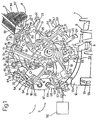
- Number 1 in the accompanying drawings indicates a device for withdrawing and depositing semirigid cartons 2, each of which comprises a substantially parallelepiped tubular body 3 (only two shown in Figure 1) and is made of cardboard or similar material. More specifically, each of the faces defining each body 3 is defined by two preformed bend lines, each of which defines a hinge between the respective adjacent faces to enable the two faces to rotate with respect to each other. As such, the cross section of body 3 may selectively assume a flat rhomboidal shape of substantially zero height to occupy as little space as possible, or a rectangular shape to receive a product in known manner.
- tubular body 3 of carton 2 are connected to lateral tabs 103 and central tabs 104. More specifically, the lateral tabs are four in number and connected to the short edges of the two openings of tubular body 3; and the central tabs are two in number and connected to a first long edge of one opening and to a second long edge of the other opening; the first and second edges forming part of opposite faces of tubular body 3.
- Device 1 comprises a First In - First out (FIFO) store 4 housing a stack of cartons 2 with bodies 3 flat and oriented in a substantially horizontal longitudinal direction 5 ( Figure 2), and from which cartons 2 are withdrawn from the bottom; a release station 6 for releasing cartons 2, located beneath store 4, and in turn comprising an endless conveyor 7 with a number of equally spaced pockets 8; a shaft 9 located between store 4 and station 6, and having a horizontal longitudinal axis 10 parallel to direction 5; and a withdrawing assembly 11 fitted to shaft 9.
- Assembly 11 provides for withdrawing cartons 2 from the bottom of store 4, imparting a rectangular cross section to cartons 2, feeding each carton 2 on to a chute 12 in station 6, and subsequently releasing carton 2 inside a respective pocket 8 on conveyor 7.
- chute 12 is defined by two shaped panels 12a, the base of each of which is fitted at the end with a threaded pin engaging a slot 12c in a support 12b to adjust the position of chute 12 according to the size of bodies 3.
- a known product conveyor 101 is provided parallel to conveyor 7, and comprises a succession of boxes 102, each defined by a U-shaped portion facing upwards so that an open end faces conveyor 7, and each so positioned and moved as to be substantially parallel to and facing a respective pocket 8.
- a known product loading device (not shown) provides for depositing inside each box 102 a product 105, which is later inserted in known manner inside a respective open carton 2 inside respective pocket 8.
- Assembly 11 comprises a given number of radial arms 13 (five in the example shown), each of which is connected in freely rotating, axially-fixed manner to shaft 9 by a respective fork 14 (Figure 2) so formed as to permit the other arms 13 to rotate about shaft 9.
- Each arm 13 comprises an elongated C-shaped support 15 in turn comprising a base 16 integral with fork 14 and from which extends radially a flat, substantially radial plate 17.
- plate 17 terminates with a flat plate 18 perpendicular to plate 17; and plates 17 and 18 are connected to each other and to base 16 by a further flat plate 19 to the rear of and perpendicular to plates 17 and 18.
- support 15 houses a gripping member 22, which, by means of rods 20, slides radially, is angularly fixed, and is fitted integrally with an elongated, rod-shaped pneumatic gripping head 23 parallel to axis 10 and comprising a pair of aligned suction cups 24.
- assembly 11 also comprises an annular body 25 coaxial with and fitted in axially-fixed manner to shaft 9 as described in detail later on.
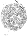
- Annular body 25 rotates continuously anticlockwise (in Figures 1 and 3), and comprises an inner cylindrical edge coaxial with shaft 9 and having a given number of toothed portions 26 equally spaced about axis 10.
- each arm 13 comprises a pin 27 parallel to axis 10 and having an end 28 extending on the opposite side of plate 19 to plate 18.
- Each end 28 is fitted in angularly-fixed manner with a sector gear 29 meshing with a respective portion 26, so that each oscillation of sector gear 29 on portion 26 corresponds to a substantially identical oscillation of respective arm 13.
- assembly 11 comprises an actuating device 30, in turn comprising a flange 31 fitted to shaft 9 to the rear of annular body 25.
- flange 31 comprises a flat annular groove 32 defined by an inner edge 33 and an outer edge 34 facing each other, parallel to axis 10, and having a step so as to define a cam 35 and a cam 36 adjacent to each other and separated by said step.
- device 30 comprises a pin 37 parallel to pin 27, having one free end housed inside a hole in the body of sector gear 29, and fitted on the other free end with a pair of eccentric tappet rollers 38 and 39 respectively engaging cam 35 and cam 36.
- roller 38 is tangent to cam 35 at edge 34
- roller 39 is tangent to cam 36 at edge 33.
- the whole comprising cams 35 and 36 and respective rollers 38 and 39 therefore defines a slack takeup device 40 wherein roller 38 keeps roller 39 contacting respective edge 33, and roller 39 keeps roller 38 contacting edge 34 to eliminate any in-service oscillation of pin 37.
- Groove 32 comprises a number of active portions arranged in series and for determining oscillation of respective sector gear 29 with respect to a respective idle position, and so selectively delaying or anticipating rotation of arm 13 about axis 10 with respect to annular body 25, as explained in more detail later on.
- the "active portion” of a cam or annular groove is intended to mean a portion of the cam or groove which so activates the respective tappet connected to the cam or groove as to vary the distance between the tappet and the axis of rotation of the cam or the longitudinal axis about which the groove extends (axis 10 in the case of assembly 11).
- an “inactive portion” is intended to mean a substantially circular portion for maintaining the corresponding tappet in a fixed position.
- assembly 11 also comprises a further actuating device 41 comprising, for each gripping member 22, a pin 42 parallel to pin 27, having a respective free end housed inside a hole in the body of member 22 beneath suction cups 24, and fitted on the other free end, facing annular body 25, with a tappet roller 44 engaging one of a number of grooves 45, each of which is formed, on the arm 13 side, on the face of a radial portion 46 of annular body 25 extending about the same arc as one of toothed portions 26.
- Each groove 45 is so shaped as to move gripping member 22 between a position at a minimum distance and a position at a maximum distance from axis 10, as explained in detail later on.
- assembly 11 also comprises a wheel 47 coaxial with axis 10, of a larger outside diameter than annular body 25, fitted in angularly free manner to shaft 9, and in turn supporting annular body 25 via the interposition of a sleeve 48, which has an inside diameter larger than the outside diameter of flange 31, extends about the same portion of shaft 9 to which flange 31 is fitted, and therefore houses flange 31.
- Wheel 47 is rotated anticlockwise (in Figure 3) by an electric motor 49 (shown schematically in Figure 2) to which it is connected in angularly fixed manner by a sleeve 50 coaxial with and connected in angularly free manner to shaft 9.
- wheel 47 comprises a number of cavities 51, each comprising two parallel lateral walls 52 extending perpendicularly from a bottom wall 53 located tangentially with respect to a cylindrical surface coaxial with axis 10 and of a radius equal to the distance between wall 53 and axis 10. Cavities 51 are equally spaced about axis 10, are equal in number to portions 26, and are delayed with respect to portions 26 in the rotation direction of annular body 25.
- a pair of filtering members 54 ( Figure 1) of a known pneumatic circuit extends from each wall 53, and each member 54 houses a known pellet filter (not shown), which is easily accessible and easily changed by unscrewing a cylindrical cap on top.
- Wheel 47 also comprises a number of cylindrical longitudinal seats 55, which are equally spaced about axis 10, have respective central axes 55a located about a circumference with its center at axis 10 and of a radius approximately equal to but no less than the distance between plates 18 and axis 10, and precede toothed portions 26 in the anticlockwise rotation direction in Figure 3.
- each seat 55 houses a pin 56 (only one shown in Figure 2) terminating on the arm 13 side with a rod 57 parallel to axis 10, so as to define a flexing tool 58 (only one shown in Figure 2) fitted with a pair of suction cups 59 substantially identical to suction cups 24, and for cooperating with one of the downward-facing faces of carton 2, as explained in detail later on.
- Pin 56 also comprises an end portion 60 projecting from seat 55 on the opposite side to rod 57, and fitted integrally with a pinion 61.
- wheel 47 also comprises an angularly free pin 62 delayed with respect to pinion 61, projecting from the rear of wheel 47, and fitted integrally with a sector gear 63 meshing with pinion 61 for the purpose described later on.
- Assembly 11 also comprises a further actuating device 64 in turn comprising a flange 65, which is connected in angularly free manner to sleeve 50, is angularly fixed in known manner (not shown) with respect to shaft 9, and has an annular groove 66 facing wheel 47.
- each sector gear 63 comprises a pin 67 parallel to axis 10 and engaging annular groove 66, which, as described in detail later on, comprises a series of active portions for rotating (with reference to Figure 2) sector gear 63 anticlockwise, pinion 61 clockwise, and, more importantly, flexing tool 58 clockwise.
- groove 66 is defined by an inner edge 68 and an edge 69 facing each other, parallel to axis 10, and having a step so as to define a cam 70 and a cam 71 adjacent to each other and separated by said step.
- device 64 On the other free end of each pin 67, device 64 comprises a pair of eccentric tappet rollers 73 and 74 respectively engaging cam 70 and cam 71.
- roller 73 is tangent to cam 70 at edge 69
- roller 74 is tangent to cam 71 at edge 68, so that the whole comprising cams 70 and 71 and respective rollers 73 and 74 defines a slack takeup device 75 wherein roller 73 keeps roller 74 contacting respective edge 68, and roller 74 keeps roller 73 contacting edge 69 to eliminate any in-service oscillation of pin 67.
- Groove 66 comprises a number of active portions in series with one another and for oscillating respective sector gear 63 with respect to a respective idle position, and so selectively delaying or anticipating rotation of flexing tools 58 about respective axes 45, as explained in detail later on.
- each arm 13 corresponds with a gripping head 23 and a flexing tool 58, which therefore rotate together at constant angular speed about axis 10; at store 4 and station 6, each arm 13 is moved by device 30 to and from a respective idle position in which arm 13 is at rest with respect to annular body 25; at store 4 and station 6, each gripping head 23 is moved by device 41 between said maximum and minimum distance positions from axis 10; and each flexing tool 58 is oscillated with respect to the respective idle position at store 4 and station 6.
- rollers 38 and 39 engage an inactive portion 76 of respective groove 32, so that pin 37 keeps the corresponding sector gear 29 at rest with respect to respective portion 26; roller 44 of respective gripping member 22 engages an inactive portion 77 ( Figure 3) of groove 45, so that gripping member 22 and head 23 are maintained in the respective minimum distance position from axis 10; and pin 67 of corresponding sector gear 59 engages an inactive portion 78 ( Figure 3) of groove 66, so that flexing tool 58 is stationary in a respective idle position.
- roller 44 engages an active portion 80 ( Figure 3) of respective groove 45, which increases the distance between roller 44 and axis 10 until, during the pause in the movement of arm 13, head 23 is set to the respective maximum distance position in which respective suction cups 24 contact and integrally engage by suction one of the two downward-facing faces of body 3.
- rollers 73 and 74 travel along an active portion 81 ( Figure 3) of groove 66, which, by means of pin 67, causes suction cups 59 of flexing tool 58 to contact and integrally engage by suction the other downward-facing face of body 3.
- tubular body 3 maintains its parallelepiped shape in the absence of external force, even when, on nearing station 6, an active portion 82 of groove 66 ( Figure 3) causes pin 67 to restore flexing tool 58 to its original position, so that suction cups 59 of flexing tool 58, by now no longer needed, release the respective face of carton 2.
- head 23 At the end of active portion 83, head 23 is positioned facing a pocket 8, and pin 37 encounters a portion 84 ( Figure 3) of groove 32 substantially equivalent to portion 79, so that arm 13 slows down until it is eventually moving substantially at rest with respect to, and over, pocket 8.
- This type of release is imposed by member 22 being unable to move down into pocket 8 to deposit carton 2 on to the bottom of the pocket, but is in no way disadvantageous, in that the carton falls only a short distance, at slow speed (the carton is made of cardboard or similar, is empty, and falls solely by force of gravity), and along an ideal trajectory imposed by the walls of pocket 8.
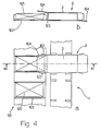
- each pocket 8 on the conveyor is associated with a corresponding box 102 on product conveyor 101; and, as shown in Figure 4, carton 2 is so deposited that, in the final position inside pocket 8, a central tab 104 of carton 2 is positioned over box 102 and the product 105 inside the box, and the lateral tabs 103, facing box 102, of carton 2 are positioned outside the box.
- Depositing the carton in this way provides for troublefree insertion of product 105 inside carton 2, which is normally effected by means of a known loading device (not shown) which pushes product 105 from box 102 into tubular body 3 of carton 2.
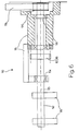
- Device 110 comprises a pair of flexing members 111 integral with a shaft 112 of axis 113 substantially parallel to the rotation axis of device 1.
- Shaft 112 is supported on bearings 114 in turn supported on a structure 115, and is integral with a first gear 116 meshing with a second gear 117.
- Second gear 117 is supported on bearings 118 in turn supported on structure 115, and is driven by a pulley 120 in turn driven by a belt 119 driven by a known drive device (not shown).
- Flexing member 111 substantially comprises a cylindrical sector, and therefore has a pressure surface 121 substantially defined by a lateral surface portion of a cylinder.
- flexing members 111 are fitted to shaft 112 in such a manner as to be changed easily according to the type of carton 2.
- the effectiveness of flexing member 111 obviously increases in proportion to its angle and diameter; the first being due to the fact that, for a given rotation speed, the greater the angle, the longer carton 2 is subjected to the action of member 111; and the second being due to the fact that, for a given distance between carton 2 and rotation axis 113, the greater the diameter, the greater the deformation imposed by member 111.
- shaft 112 is rotated at a multiple angular speed synchronized with the angular speed of device 1. More specifically, the angular speed of shaft 112 equals the angular speed of device 1 multiplied by the number of radial arms 13 provided (five in the example shown) so as to enable the flexing cycle to be repeated for each carton 2 traveling past device 110.
- the angular speed of shaft 112 is so timed that pressure surface 121 interacts with the outer face of carton 2 (i.e. the face parallel to and opposite the one retained by suction cups 24) as carton 2 travels within the operating region of device 110; which region corresponds with that in which the action of flexing device 110 ceases and suction cups 59 release carton 2, which at that point tends to return to its original shape.
- Device 110 is particularly useful, in fact, by further flexing the carton precisely as it tends to return to its original closed configuration; and numerous tests have shown that a second flexing operation provides for safely maintaining the desired shape of carton 2.
- Flexing member 111 is rotated in the opposite direction to device 1, so that the surface speed of carton 2 is equal in direction to the surface speed of members 111, and carton 2 is flexed gently with no risk of damage.
- Device 1 may therefore be used to considerable advantage for preparing cartons 2 to receive the products, and for depositing cartons 2 inside respective pockets 8 with respective tubular bodies 3 ready to receive the products from a machine downstream from device 1.
Landscapes
- Engineering & Computer Science (AREA)
- Mechanical Engineering (AREA)
- Supplying Of Containers To The Packaging Station (AREA)
- Making Paper Articles (AREA)
- Yarns And Mechanical Finishing Of Yarns Or Ropes (AREA)
- Pressure Welding/Diffusion-Bonding (AREA)
Applications Claiming Priority (2)
| Application Number | Priority Date | Filing Date | Title |
|---|---|---|---|
| IT96BO000252A IT1285690B1 (it) | 1996-05-08 | 1996-05-08 | Dispositivo di prelievo e posa di astucci semirigidi |
| ITBO960252 | 1996-05-08 |
Publications (2)
| Publication Number | Publication Date |
|---|---|
| EP0806292A2 true EP0806292A2 (de) | 1997-11-12 |
| EP0806292A3 EP0806292A3 (de) | 1999-03-31 |
Family
ID=11341388
Family Applications (1)
| Application Number | Title | Priority Date | Filing Date |
|---|---|---|---|
| EP97107559A Withdrawn EP0806292A3 (de) | 1996-05-08 | 1997-05-07 | Vorrichtung zur Entnahme und zum Einlegen von halbsteifen Kartonbehältern |
Country Status (3)
| Country | Link |
|---|---|
| EP (1) | EP0806292A3 (de) |
| JP (1) | JPH1053220A (de) |
| IT (1) | IT1285690B1 (de) |
Cited By (3)
| Publication number | Priority date | Publication date | Assignee | Title |
|---|---|---|---|---|
| WO2011047810A1 (de) * | 2009-10-20 | 2011-04-28 | Iwk Verpackungstechnik Gmbh | Übergabevorrichtung zur übergabe einer faltschachtel |
| ITBO20110263A1 (it) * | 2011-05-11 | 2012-11-12 | O A M Societa Per Azioni | Apparato di confezionamento, particolarmente del tipo di astucciatrici e simili. |
| CN107600544A (zh) * | 2017-09-30 | 2018-01-19 | 辽宁春光制药装备股份有限公司 | 装盒机高速取盒装置 |
Family Cites Families (6)
| Publication number | Priority date | Publication date | Assignee | Title |
|---|---|---|---|---|
| JPS53140777A (en) * | 1977-03-18 | 1978-12-08 | Martelli G | Apparatus for taking out semiirigid sheettshaped element and send it to conveyer |
| IT1133252B (it) * | 1980-03-18 | 1986-07-09 | Massimo Marchesini | Macchina automatica per il confezionamento continuo di prodotti |
| IT1213662B (it) * | 1987-07-30 | 1989-12-29 | Ima Spa | Apparecchiatura per alimentare sbozzati di materiale per l'imballaggio e particolarmente per l'alimentazione e l'erezione in astucci di confezionamento di sbozzati tubolari ripiegati appiattiti nelle macchine confezionatrici di confezioni blisters |
| DE3941867A1 (de) * | 1989-12-19 | 1991-06-20 | Bosch Gmbh Robert | Vorrichtung zum ueberfuehren flacher gegenstaende, insbesondere faltschachteln |
| US5176612A (en) * | 1991-12-13 | 1993-01-05 | The Mead Corporation | High speed erecting mechanism for sleeve type carton |
| IT1274052B (it) * | 1994-10-07 | 1997-07-14 | Azionaria Costruzioni Automati | Metodo per l'espansione di astucci e per la loro alimentazione ad una linea di riempimento. |
-
1996
- 1996-05-08 IT IT96BO000252A patent/IT1285690B1/it active IP Right Grant
-
1997
- 1997-05-07 EP EP97107559A patent/EP0806292A3/de not_active Withdrawn
- 1997-05-08 JP JP9118411A patent/JPH1053220A/ja active Pending
Cited By (5)
| Publication number | Priority date | Publication date | Assignee | Title |
|---|---|---|---|---|
| WO2011047810A1 (de) * | 2009-10-20 | 2011-04-28 | Iwk Verpackungstechnik Gmbh | Übergabevorrichtung zur übergabe einer faltschachtel |
| US8919533B2 (en) | 2009-10-20 | 2014-12-30 | Iwk Verpackungstechnik Gmbh | Transfer device for the transfer of a folding box |
| ITBO20110263A1 (it) * | 2011-05-11 | 2012-11-12 | O A M Societa Per Azioni | Apparato di confezionamento, particolarmente del tipo di astucciatrici e simili. |
| EP2522578A3 (de) * | 2011-05-11 | 2012-12-12 | O.A.M. - Societa' per Azioni | Verpackungsvorrichtung, insbesondere Kartoniermaschine und dergleichen |
| CN107600544A (zh) * | 2017-09-30 | 2018-01-19 | 辽宁春光制药装备股份有限公司 | 装盒机高速取盒装置 |
Also Published As
| Publication number | Publication date |
|---|---|
| ITBO960252A0 (it) | 1996-05-08 |
| EP0806292A3 (de) | 1999-03-31 |
| ITBO960252A1 (it) | 1997-11-08 |
| JPH1053220A (ja) | 1998-02-24 |
| IT1285690B1 (it) | 1998-06-18 |
Similar Documents
| Publication | Publication Date | Title |
|---|---|---|
| EP0425226B1 (de) | Schnittstelle zum Übergang von kontinuierlicher zu schrittweiser Zufuhr | |
| US6527102B2 (en) | Installation for forming batches of articles | |
| EP0705684A1 (de) | Verfahren zum Aufrichten und Zuführen zu einer Abfüllinie von Faltschachteln | |
| RU2136553C1 (ru) | Способ транспортировки объектов через устройство (варианты), упаковочное устройство (варианты) и способ упаковки материалов в картонные пакеты (варианты) | |
| US2734657A (en) | Drese | |
| EP0414774B1 (de) | Gerät zur fortbewegung | |
| US3191357A (en) | Apparatus for packaging confections | |
| EP0030304A1 (de) | Drehvorrichtung zur Bildung von gleichgrossen Gruppen von Gegenständen insbes. Fliesen | |
| EP1707491B1 (de) | Vorrichtung zum Greifen und Aufmachen von Schachteln für die Verpackung von Produkten | |
| US5511364A (en) | Apparatus for packing products in preformed bags | |
| CA1042030A (en) | Method and apparatus for transferring cans | |
| US7220094B2 (en) | Transfer device for cylindrical stacks of products arranged on an edge | |
| US4902192A (en) | Article control assembly for article transfer device | |
| EP0806292A2 (de) | Vorrichtung zur Entnahme und zum Einlegen von halbsteifen Kartonbehältern | |
| US5431038A (en) | Apparatus for feeding a workpiece to a tool | |
| EP0806291A2 (de) | Apparat zur Übergabe von halbstarren Kartonbehältern | |
| EP1719703B1 (de) | Vorrichtung zum Verpacken von Gegenständen in Schachteln | |
| WO1998052825A1 (en) | Feeder mechanism and hopper for collapsed carton blanks | |
| JP3901730B2 (ja) | 物品選択・送り出し方法及び装置 | |
| US3611675A (en) | Apparatus for wrapping articles | |
| US4685554A (en) | Ejection method and apparatus | |
| HUP0100477A2 (hu) | Berendezés adagólószerkezetekkel és tárakkal két különböző típusú kartondobozhoz | |
| EP0926071A1 (de) | Einheit zum Glätten von umwickelten Schokoladeprodukten | |
| CA2595494C (en) | Article selection and delivery method and apparatus | |
| WO2023026310A1 (en) | Apparatus and method for making flexible shaped portions on tubular elements |
Legal Events
| Date | Code | Title | Description |
|---|---|---|---|
| PUAI | Public reference made under article 153(3) epc to a published international application that has entered the european phase |
Free format text: ORIGINAL CODE: 0009012 |
|
| AK | Designated contracting states |
Kind code of ref document: A2 Designated state(s): DE ES FR GB |
|
| PUAL | Search report despatched |
Free format text: ORIGINAL CODE: 0009013 |
|
| AK | Designated contracting states |
Kind code of ref document: A3 Designated state(s): DE ES FR GB |
|
| STAA | Information on the status of an ep patent application or granted ep patent |
Free format text: STATUS: THE APPLICATION IS DEEMED TO BE WITHDRAWN |
|
| 18D | Application deemed to be withdrawn |
Effective date: 19991002 |