EP0806314B1 - Transmission hybride avec régulation de mode de conduite parmi des embrayages - Google Patents
Transmission hybride avec régulation de mode de conduite parmi des embrayages Download PDFInfo
- Publication number
- EP0806314B1 EP0806314B1 EP96303257A EP96303257A EP0806314B1 EP 0806314 B1 EP0806314 B1 EP 0806314B1 EP 96303257 A EP96303257 A EP 96303257A EP 96303257 A EP96303257 A EP 96303257A EP 0806314 B1 EP0806314 B1 EP 0806314B1
- Authority
- EP
- European Patent Office
- Prior art keywords
- electrical machine
- engine
- transmission shaft
- gear
- speed
- Prior art date
- Legal status (The legal status is an assumption and is not a legal conclusion. Google has not performed a legal analysis and makes no representation as to the accuracy of the status listed.)
- Expired - Lifetime
Links
Images


Classifications
-
- B—PERFORMING OPERATIONS; TRANSPORTING
- B60—VEHICLES IN GENERAL
- B60K—ARRANGEMENT OR MOUNTING OF PROPULSION UNITS OR OF TRANSMISSIONS IN VEHICLES; ARRANGEMENT OR MOUNTING OF PLURAL DIVERSE PRIME-MOVERS IN VEHICLES; AUXILIARY DRIVES FOR VEHICLES; INSTRUMENTATION OR DASHBOARDS FOR VEHICLES; ARRANGEMENTS IN CONNECTION WITH COOLING, AIR INTAKE, GAS EXHAUST OR FUEL SUPPLY OF PROPULSION UNITS IN VEHICLES
- B60K6/00—Arrangement or mounting of plural diverse prime-movers for mutual or common propulsion, e.g. hybrid propulsion systems comprising electric motors and internal combustion engines
- B60K6/20—Arrangement or mounting of plural diverse prime-movers for mutual or common propulsion, e.g. hybrid propulsion systems comprising electric motors and internal combustion engines the prime-movers consisting of electric motors and internal combustion engines, e.g. HEVs
- B60K6/22—Arrangement or mounting of plural diverse prime-movers for mutual or common propulsion, e.g. hybrid propulsion systems comprising electric motors and internal combustion engines the prime-movers consisting of electric motors and internal combustion engines, e.g. HEVs characterised by apparatus, components or means specially adapted for HEVs
- B60K6/38—Arrangement or mounting of plural diverse prime-movers for mutual or common propulsion, e.g. hybrid propulsion systems comprising electric motors and internal combustion engines the prime-movers consisting of electric motors and internal combustion engines, e.g. HEVs characterised by apparatus, components or means specially adapted for HEVs characterised by the driveline clutches
- B60K6/383—One-way clutches or freewheel devices
-
- B—PERFORMING OPERATIONS; TRANSPORTING
- B60—VEHICLES IN GENERAL
- B60K—ARRANGEMENT OR MOUNTING OF PROPULSION UNITS OR OF TRANSMISSIONS IN VEHICLES; ARRANGEMENT OR MOUNTING OF PLURAL DIVERSE PRIME-MOVERS IN VEHICLES; AUXILIARY DRIVES FOR VEHICLES; INSTRUMENTATION OR DASHBOARDS FOR VEHICLES; ARRANGEMENTS IN CONNECTION WITH COOLING, AIR INTAKE, GAS EXHAUST OR FUEL SUPPLY OF PROPULSION UNITS IN VEHICLES
- B60K6/00—Arrangement or mounting of plural diverse prime-movers for mutual or common propulsion, e.g. hybrid propulsion systems comprising electric motors and internal combustion engines
- B60K6/20—Arrangement or mounting of plural diverse prime-movers for mutual or common propulsion, e.g. hybrid propulsion systems comprising electric motors and internal combustion engines the prime-movers consisting of electric motors and internal combustion engines, e.g. HEVs
- B60K6/42—Arrangement or mounting of plural diverse prime-movers for mutual or common propulsion, e.g. hybrid propulsion systems comprising electric motors and internal combustion engines the prime-movers consisting of electric motors and internal combustion engines, e.g. HEVs characterised by the architecture of the hybrid electric vehicle
- B60K6/48—Parallel type
-
- B—PERFORMING OPERATIONS; TRANSPORTING
- B60—VEHICLES IN GENERAL
- B60L—PROPULSION OF ELECTRICALLY-PROPELLED VEHICLES; SUPPLYING ELECTRIC POWER FOR AUXILIARY EQUIPMENT OF ELECTRICALLY-PROPELLED VEHICLES; ELECTRODYNAMIC BRAKE SYSTEMS FOR VEHICLES IN GENERAL; MAGNETIC SUSPENSION OR LEVITATION FOR VEHICLES; MONITORING OPERATING VARIABLES OF ELECTRICALLY-PROPELLED VEHICLES; ELECTRIC SAFETY DEVICES FOR ELECTRICALLY-PROPELLED VEHICLES
- B60L50/00—Electric propulsion with power supplied within the vehicle
- B60L50/10—Electric propulsion with power supplied within the vehicle using propulsion power supplied by engine-driven generators, e.g. generators driven by combustion engines
- B60L50/15—Electric propulsion with power supplied within the vehicle using propulsion power supplied by engine-driven generators, e.g. generators driven by combustion engines with additional electric power supply
-
- B—PERFORMING OPERATIONS; TRANSPORTING
- B60—VEHICLES IN GENERAL
- B60W—CONJOINT CONTROL OF VEHICLE SUB-UNITS OF DIFFERENT TYPE OR DIFFERENT FUNCTION; CONTROL SYSTEMS SPECIALLY ADAPTED FOR HYBRID VEHICLES; ROAD VEHICLE DRIVE CONTROL SYSTEMS FOR PURPOSES NOT RELATED TO THE CONTROL OF A PARTICULAR SUB-UNIT
- B60W10/00—Conjoint control of vehicle sub-units of different type or different function
- B60W10/02—Conjoint control of vehicle sub-units of different type or different function including control of driveline clutches
-
- B—PERFORMING OPERATIONS; TRANSPORTING
- B60—VEHICLES IN GENERAL
- B60W—CONJOINT CONTROL OF VEHICLE SUB-UNITS OF DIFFERENT TYPE OR DIFFERENT FUNCTION; CONTROL SYSTEMS SPECIALLY ADAPTED FOR HYBRID VEHICLES; ROAD VEHICLE DRIVE CONTROL SYSTEMS FOR PURPOSES NOT RELATED TO THE CONTROL OF A PARTICULAR SUB-UNIT
- B60W10/00—Conjoint control of vehicle sub-units of different type or different function
- B60W10/04—Conjoint control of vehicle sub-units of different type or different function including control of propulsion units
- B60W10/08—Conjoint control of vehicle sub-units of different type or different function including control of propulsion units including control of electric propulsion units, e.g. motors or generators
-
- B—PERFORMING OPERATIONS; TRANSPORTING
- B60—VEHICLES IN GENERAL
- B60K—ARRANGEMENT OR MOUNTING OF PROPULSION UNITS OR OF TRANSMISSIONS IN VEHICLES; ARRANGEMENT OR MOUNTING OF PLURAL DIVERSE PRIME-MOVERS IN VEHICLES; AUXILIARY DRIVES FOR VEHICLES; INSTRUMENTATION OR DASHBOARDS FOR VEHICLES; ARRANGEMENTS IN CONNECTION WITH COOLING, AIR INTAKE, GAS EXHAUST OR FUEL SUPPLY OF PROPULSION UNITS IN VEHICLES
- B60K6/00—Arrangement or mounting of plural diverse prime-movers for mutual or common propulsion, e.g. hybrid propulsion systems comprising electric motors and internal combustion engines
- B60K6/20—Arrangement or mounting of plural diverse prime-movers for mutual or common propulsion, e.g. hybrid propulsion systems comprising electric motors and internal combustion engines the prime-movers consisting of electric motors and internal combustion engines, e.g. HEVs
- B60K6/22—Arrangement or mounting of plural diverse prime-movers for mutual or common propulsion, e.g. hybrid propulsion systems comprising electric motors and internal combustion engines the prime-movers consisting of electric motors and internal combustion engines, e.g. HEVs characterised by apparatus, components or means specially adapted for HEVs
- B60K6/26—Arrangement or mounting of plural diverse prime-movers for mutual or common propulsion, e.g. hybrid propulsion systems comprising electric motors and internal combustion engines the prime-movers consisting of electric motors and internal combustion engines, e.g. HEVs characterised by apparatus, components or means specially adapted for HEVs characterised by the motors or the generators
- B60K2006/268—Electric drive motor starts the engine, i.e. used as starter motor
-
- Y—GENERAL TAGGING OF NEW TECHNOLOGICAL DEVELOPMENTS; GENERAL TAGGING OF CROSS-SECTIONAL TECHNOLOGIES SPANNING OVER SEVERAL SECTIONS OF THE IPC; TECHNICAL SUBJECTS COVERED BY FORMER USPC CROSS-REFERENCE ART COLLECTIONS [XRACs] AND DIGESTS
- Y02—TECHNOLOGIES OR APPLICATIONS FOR MITIGATION OR ADAPTATION AGAINST CLIMATE CHANGE
- Y02T—CLIMATE CHANGE MITIGATION TECHNOLOGIES RELATED TO TRANSPORTATION
- Y02T10/00—Road transport of goods or passengers
- Y02T10/60—Other road transportation technologies with climate change mitigation effect
- Y02T10/62—Hybrid vehicles
-
- Y—GENERAL TAGGING OF NEW TECHNOLOGICAL DEVELOPMENTS; GENERAL TAGGING OF CROSS-SECTIONAL TECHNOLOGIES SPANNING OVER SEVERAL SECTIONS OF THE IPC; TECHNICAL SUBJECTS COVERED BY FORMER USPC CROSS-REFERENCE ART COLLECTIONS [XRACs] AND DIGESTS
- Y02—TECHNOLOGIES OR APPLICATIONS FOR MITIGATION OR ADAPTATION AGAINST CLIMATE CHANGE
- Y02T—CLIMATE CHANGE MITIGATION TECHNOLOGIES RELATED TO TRANSPORTATION
- Y02T10/00—Road transport of goods or passengers
- Y02T10/60—Other road transportation technologies with climate change mitigation effect
- Y02T10/70—Energy storage systems for electromobility, e.g. batteries
-
- Y—GENERAL TAGGING OF NEW TECHNOLOGICAL DEVELOPMENTS; GENERAL TAGGING OF CROSS-SECTIONAL TECHNOLOGIES SPANNING OVER SEVERAL SECTIONS OF THE IPC; TECHNICAL SUBJECTS COVERED BY FORMER USPC CROSS-REFERENCE ART COLLECTIONS [XRACs] AND DIGESTS
- Y02—TECHNOLOGIES OR APPLICATIONS FOR MITIGATION OR ADAPTATION AGAINST CLIMATE CHANGE
- Y02T—CLIMATE CHANGE MITIGATION TECHNOLOGIES RELATED TO TRANSPORTATION
- Y02T10/00—Road transport of goods or passengers
- Y02T10/60—Other road transportation technologies with climate change mitigation effect
- Y02T10/7072—Electromobility specific charging systems or methods for batteries, ultracapacitors, supercapacitors or double-layer capacitors
-
- Y—GENERAL TAGGING OF NEW TECHNOLOGICAL DEVELOPMENTS; GENERAL TAGGING OF CROSS-SECTIONAL TECHNOLOGIES SPANNING OVER SEVERAL SECTIONS OF THE IPC; TECHNICAL SUBJECTS COVERED BY FORMER USPC CROSS-REFERENCE ART COLLECTIONS [XRACs] AND DIGESTS
- Y10—TECHNICAL SUBJECTS COVERED BY FORMER USPC
- Y10S—TECHNICAL SUBJECTS COVERED BY FORMER USPC CROSS-REFERENCE ART COLLECTIONS [XRACs] AND DIGESTS
- Y10S903/00—Hybrid electric vehicles, HEVS
- Y10S903/902—Prime movers comprising electrical and internal combustion motors
- Y10S903/903—Prime movers comprising electrical and internal combustion motors having energy storing means, e.g. battery, capacitor
- Y10S903/904—Component specially adapted for hev
- Y10S903/912—Drive line clutch
- Y10S903/913—One way
-
- Y—GENERAL TAGGING OF NEW TECHNOLOGICAL DEVELOPMENTS; GENERAL TAGGING OF CROSS-SECTIONAL TECHNOLOGIES SPANNING OVER SEVERAL SECTIONS OF THE IPC; TECHNICAL SUBJECTS COVERED BY FORMER USPC CROSS-REFERENCE ART COLLECTIONS [XRACs] AND DIGESTS
- Y10—TECHNICAL SUBJECTS COVERED BY FORMER USPC
- Y10S—TECHNICAL SUBJECTS COVERED BY FORMER USPC CROSS-REFERENCE ART COLLECTIONS [XRACs] AND DIGESTS
- Y10S903/00—Hybrid electric vehicles, HEVS
- Y10S903/902—Prime movers comprising electrical and internal combustion motors
- Y10S903/903—Prime movers comprising electrical and internal combustion motors having energy storing means, e.g. battery, capacitor
- Y10S903/946—Characterized by control of driveline clutch
Definitions
- US-A-5 427 196 describes a known multiple function combined power system, according to the preamble of claim 1.
- This invention relates to a multiple function combined power system which is used in driving machinery such as vehicles, ships, flying machines or other mechanical structures, or other industrial or processing equipment, in rotation driving application, and in which the rotational output shaft of an internal combustion engine is coupled with an electrical machine through transmission gears, belts, or chains which constitute a particular transmission device installed between the electrical machine, engine and the output shaft.
- the electrical machine is a series excited or auxiliary compound excited electrical machine with the electrical characteristic that its rotational speed increases with a decreasing load, or an AC or DC brush or brushless machine able to perform current control, including constant current control to provide a load-following value-added torque function, and is coupled with the engine output shaft through a particular transmission device operated in two system modes following the driving direction of the electrical machine, by means of a one-way clutch and an eccentric clutch in cooperation with control of the rotation directions of the electrical machine to cause (1) the electrical machine to start the engine, (2) the electrical machine to be used as a generator during engine operation, (3) the electrical machine and the engine to drive the load at the same time during the engine operation, (4) the electrical machine to drive the load, and (5) when the load is standing still, the engine to drive the electrical machine in a generator mode to charge the battery or other electrical loads.
- Figure 1 is a side view of a first preferred embodiment invention.
- Figure 2 is a side view of a second preferred embodiment of the invention.
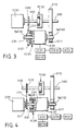
- Figure 3 is a side view of a third preferred embodiment of the invention.
- Figure 4 is side view of a fourth preferred embodiment of the invention.
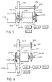
- Figure 5 is a side view of a fifth preferred embodiment of the invention.
- Figure 6 is a side view of a sixth preferred embodiment of the invention.
- Figure 7 is a side view of a seventh preferred embodiment of the invention.
- Figure 8 is a side view of an eighth preferred embodiment of the invention.
- Figure 1 shows the first preferred embodiment of the invention, including:
- FIG. 2 shows the second preferred embodiment of the multiple function combined power system of the invention, and includes the following elements:
- FIG. 3 shows the third preferred embodiment of the multiple function combined power system of the invention which includes the following elements:
- FIG. 4 shows the fourth preferred embodiment of the multiple function combined power system of the invention, including the following elements:
- FIG. 5 shows a fifth preferred embodiment of the multiple function combined power system of the invention, including the following elements:
- FIG. 6 shows the sixth preferred embodiment of the multiple function combined power system of the invention, including the following elements:
- Figure 7 shows the seventh preferred embodiment of the multiple function combined power system of the invention, including the following elements:
- FIG. 8 shows the eighth preferred embodiment of the multiple function combined power system of the invention, including the following elements:
- this design adopts a particular transmission structure coupled with the engine and the electrical machine, and thereby enables selection between having the motor start the engine or produce an independent driving output through the positive and reverse rotations of the electrical machine.
- the claimed structure is easy to operate is most practically effective for vehicles in the heavy stop and go traffic of cities.
Landscapes
- Engineering & Computer Science (AREA)
- Chemical & Material Sciences (AREA)
- Combustion & Propulsion (AREA)
- Transportation (AREA)
- Mechanical Engineering (AREA)
- Power Engineering (AREA)
- Electric Propulsion And Braking For Vehicles (AREA)
- Hybrid Electric Vehicles (AREA)
- Arrangement Of Transmissions (AREA)
- Transmission Devices (AREA)
Claims (13)
- Système d'entraínement combiné à fonctions multiples, comprenant :dans lequel l'interface manuelle de commande (M101), le contrôleur central (CCU101) et le contrôleur d'entraínement (D101) comportent des moyens pour réaliser les fonctions suivantes :un moteur à combustion interne (IC101) comportant un arbre de transmission (S102) de moteur et un arbre de transmission (S103) de sortie ;une machine électrique (E101) ;un dispositif de transmission (SWC101, SWC102) couplé à la machine électrique ;une interface manuelle de commande (M101) prévue pour permettre l'entrée manuelle des instructions de commande par un porteur d'informations approprié pour commander la machine électrique en tant que moteur ou générateur ;un contrôleur central (CCU101) prévu pour effectuer des calculs numériques de priorité sur des signaux à partir des signaux de l'interface manuelle de contrôle ou sur des signaux de rétroaction, pour générer des instructions de contrôle et commander la machine électrique en tant que moteur ou générateur ;un contrôleur d'entraínement (D101) prévu pour recevoir les instructions de commande du contrôleur central pour commander la machine électrique en tant que générateur et contrôler son niveau de puissance électrique, et pour commander la machine électrique en tant que moteur et contrôler son sens et sa vitesse de rotation ;caractérisé en ce que le premier et le second dispositif de transmission (SWC101, SWC102) unidirectionnelle sont couplés à la machine électrique, et en ce qu'au moins un parmi un premier et un second embrayage sensibles à la vitesse (FC102, FC101) est connecté pour entraíner l'arbre de transmission (S102) du moteur à combustion vers l'arbre de transmission (S103) de sortie, et prévu pour engager et réaliser la transmission au-dessus de la vitesse nominale tout en libérant et en coupant la transmission en dessous de la vitesse nominale.(1) la machine électrique (E101) est commandée par le contrôleur d'entraínement pour fonctionner en tant que moteur tournant soit dans le sens positif, soit dans le sens inverse, ou pour fonctionner en tant que générateur de charge d'une batterie (BAT101) ou alimenter d'autres charges ;(2) la machine électrique (E101) est entraínée en rotation dans le sens positif et inverse pour réaliser les opérations suivantes du système : le moteur est entraíné en rotation dans le sens positif pour démarrer le moteur à combustion, et le moteur à combustion est utilisé pour entraíner des charges après son démarrage alors que le moteur électrique est maintenu dans un état d'attente ;(3) les charges étant entraínées par le moteur à combustion (IC101), si la machine électrique (E101) est commandée en tant que générateur par l'interface manuelle de contrôle par le contrôleur central et par le contrôleur d'entraínement, alors le moteur à combustion entraíne simultanément les charges et le générateur pour charger la batterie (BAT101) ou alimenter les autres charges en énergie ;(4) tandis que les charges sont entraínées par le moteur à combustion, si la machine électrique (E101) fonctionne en moteur, alors ce moteur est alimenté en énergie par la batterie (BAT101) et entraíne les charges avec le moteur à combustion (IC101) ;(5) si la machine électrique (E101) fonctionne en tant que moteur et est entraínée en rotation dans le sens inverse, les dispositifs de transmission (SWC101, SWC102) agissent de façon que le sens de rotation des charges soit le même que s'ils étaient entraínés par le moteur à combustion (IC101), et les charges sont simplement entraínées par la machine électrique (E101) fonctionnant en moteur tandis que le moteur à combustion est dans un état stationnaire et au repos ;(6) tandis que les charges sont entraínées par le moteur à combustion, de l'énergie est récupérée en commandant la machine électrique (E101) en générateur pour charger la batterie (BAT101) ou alimenter en énergie les autres charges, ou en utilisant l'amortissement par friction du moteur à combustion lui-même pour une fonction de freinage ;(7) tandis que la machine électrique (E101) est commandée en moteur pour entraíner les charges, une récupération d'énergie est réalisée en utilisant la machine électrique (E101) en générateur pour charger la batterie (BAT101) ou alimenter d'autres charges en énergie ;(8) la machine électrique (E101) est entraínée par le moteur à combustion en générateur de courant alternatif pour charger la batterie (BAT101) ou alimenter d'autres charges en énergie ;
- Système selon la revendication 1,
caractérisé en ce que la machine électrique comporte un arbre de transmission (S101) de machine électrique monté en utilisant les dispositifs de transmission unidirectionnelle à chaque extrémité en sens opposé et en ce que le second embrayage sensible à la vitesse (FC101) est connecté pour transmettre l'énergie de la machine électrique à l'arbre de transmission de la machine électrique et prévu pour engager et réaliser la transmission au-dessus de la vitesse nominale tout en relâchant et coupant la transmission en dessous de la vitesse nominale. - Système selon la revendication 2,
caractérisé en ce que :la machine électrique comporte en outre un premier, un second et un troisième engrenage, le premier engrenage s'engageant dans le second engrenage qui est combiné avec l'arbre de transmission du moteur à combustion ;le second embrayage sensible à la vitesse est monté entre le premier engrenage et l'arbre de transmission de machine électrique et comporte un disque de friction présentant une face d'entraínement prévue pour engager le premier engrenage et une face entraínée prévue pour engager l'arbre de transmission de la machine électrique lorsque la vitesse nominale est dépassée ; etle système comprend en outre des moyens pour entraíner l'arbre de transmission du moteur à combustion et l'arbre de transmission de sortie dans le même sens de rotation. - Système selon la revendication 3,
caractérisé en ce que le premier embrayage sensible à la vitesse comprend un disque de friction présentant une face d'entraínement associée à l'arbre de transmission du moteur à combustion et une face entraínée associée à l'arbre de transmission de sortie. - Système selon la revendication 3 ou 4, caractérisé en ce que :l'arbre de transmission de la machine électrique entraíne le troisième engrenage par le second dispositif de transmission unidirectionnelle pour s'engager dans un quatrième engrenage sur l'arbre de transmission de sortie pour entraíner ainsi l'arbre de transmission de sortie ;le premier dispositif de transmission unidirectionnelle est couplé entre une roue à chaíne et l'arbre de transmission de la machine électrique ;le premier embrayage sensible à la vitesse est monté entre la roue à chaíne et l'arbre de transmission du moteur à combustion, et comporte un disque de friction présentant une face d'entraínement combinée avec la roue à chaíne et une face entraínée combinée avec l'arbre de transmission de la machine électrique ;une seconde roue à chaíne est combinée avec l'arbre de transmission du moteur à combustion et est entraínée mutuellement avec la première roue à chaíne par une chaíne ; etle second embrayage sensible à la vitesse est monté entre l'arbre de transmission du moteur à combustion et l'arbre de transmission de sortie, et le second embrayage sensible à la vitesse comporte un disque de friction présentant une face d'entraínement combinée avec l'arbre de transmission du moteur à combustion et une face entraínée combinée avec l'arbre de transmission de sortie.
- Système selon la revendication 2,
caractérisé en ce que :l'arbre de transmission de la machine électrique est disposé pour entraíner un premier engrenage dans deux sens de rotation différents à travers le premier dispositif de transmission unidirectionnelle qui est couplé à une face d'entraínement du second embrayage sensible à la vitesse de façon à être combiné avec l'arbre de transmission du moteur à combustion lorsqu'une face entraínée du second embrayage sensible à la vitesse est combinée avec l'arbre de transmission de la machine électrique, le second embrayage sensible à la vitesse présentant un disque de friction sur l'arbre de transmission du moteur à combustion prévu pour s'engager avec une roue à chaíne montée sur l'arbre de transmission du moteur à combustion ;le premier dispositif de transmission unidirectionnelle est monté entre l'arbre de transmission du moteur à combustion et l'arbre de transmission de sortie et présente un disque de friction comportant une face d'entraínement combinée avec l'arbre de transmission du moteur à combustion et une face entraínée combinée avec l'arbre de transmission de sortie ;un second engrenage est monté sur l'arbre de transmission de sortie pour s'engager dans le premier engrenage ; etle second dispositif de transmission unidirectionnelle est monté entre le premier engrenage et l'arbre de transmission de machine électrique lorsque son sens de rotation est différent de celui du premier dispositif de transmission. - Système selon la revendication 1,
caractérisé en ce que :la machine électrique comprend un arbre rotatif conformé en tube creux prévu pour renfermer le second dispositif de transmission unidirectionnelle, le second dispositif de transmission unidirectionnelle étant combiné avec l'arbre de transmission du moteur à combustion, ledit arbre rotatif étant ajusté à son tour à l'intérieur du premier dispositif de transmission unidirectionnelle et combiné avec un premier engrenage de transmission, le premier engrenage de transmission s'engageant dans un second engrenage de transmission ;le premier et le second dispositif de transmission unidirectionnelle étant prévu pour présenter des sens de rotation différents ;l'arbre de transmission du moteur à combustion est couplé à un engrenage à chaíne par le second embrayage sensible à la vitesse lorsqu'une face d'entraínement d'un disque de friction s'engage avec l'arbre de transmission du moteur à combustion et une face entraínée du disque de friction s'engage dans l'engrenage à chaíne ;un arbre de sortie est monté avec un second engrenage à chaíne qui s'engage dans le second engrenage de transmission par le second engrenage à chaíne au premier engrenage à chaíne au moyen d'une chaíne ; etl'arbre de sortie et le second engrenage à chaíne sont montés de façon à transmettre la puissance au premier engrenage de transmission. - Système selon la revendication 2,
caractérisé en ce que :la machine électrique comprend un arbre de sortie combiné avec une roue à chaíne par le second dispositif de transmission unidirectionnelle et est introduit à l'intérieur du premier dispositif de transmission unidirectionnelle pour entraíner un premier engrenage dans une seule direction ;le second embrayage sensible à la vitesse est monté entre l'arbre de sortie et le premier engrenage et comprend un disque de friction présentant une face d'entraínement combinée avec le premier engrenage et une face entraínée combinée avec l'arbre rotatif ; etl'arbre de transmission du moteur à combustion est monté avec un second engrenage pour s'engager dans le premier engrenage et une seconde roue à chaíne pour se coupler avec la première roue à chaíne par une chaíne. - Système selon la revendication 2,
caractérisé en ce que :la machine électrique comprend un arbre rotatif présentant une première et une seconde extrémité ;une première extrémité du second embrayage sensible à la vitesse est combinée avec une sortie de boíte de vitesse, et une seconde extrémité du second embrayage sensible à la vitesse est combinée avec la première extrémité de l'arbre de transmission de la machine électrique ;les charges sont entraínées par un arbre de sortie de la boíte de vitesse ;la seconde extrémité de l'arbre de transmission de la machine électrique est combinée avec l'arbre de transmission du moteur à combustion par le premier dispositif de transmission unidirectionnelle ;le premier embrayage sensible à la vitesse est monté entre l'arbre de transmission du moteur à combustion et l'arbre de transmission de la machine électrique et comprend un disque de friction comportant une face d'entraínement combinée avec l'arbre de transmission du moteur à combustion ; etla boíte de vitesse est prévue pour maintenir le même sens de rotation quel que soit le sens de rotation à son entrée. - Système selon la revendication 1,
caractérisé en ce que :la machine électrique comprend un arbre rotatif présentant une première et une seconde extrémité, la première extrémité de l'arbre rotatif de la machine électrique étant combinée avec une boíte de vitesse de sortie ;la charge est entraínée par un arbre de sortie de la boíte de vitesse ;la seconde extrémité de l'arbre rotatif de la machine électrique est combinée avec l'arbre de transmission du moteur à combustion par le premier dispositif de transmission unidirectionnelle ;l'embrayage sensible à la vitesse est monté entre l'arbre de transmission du moteur à combustion et comprend un disque de friction présentant une face d'entraínement combinée avec l'arbre de transmission du moteur à combustion et une face entraínée combinée avec l'arbre rotatif de machine électrique ; etla boíte de vitesse est prévue pour maintenir le même sens directionnel quel que soit le sens de rotation à son entrée. - Système selon la revendication 1,
caractérisé en ce que le premier embrayage sensible à la vitesse est monté entre la machine électrique et le moteur à combustion, en ce qu'un second embrayage sensible à la vitesse est monté entre la machine électrique et une charge, et en ce que le second embrayage sensible à la vitesse présente une vitesse nominale plus élevée que le premier embrayage sensible à la vitesse de façon que le moteur à combustion puisse être commandé à faible vitesse tandis que le second embrayage sensible à la vitesse est maintenu dans un état relâché pour permettre à une batterie d'être chargée par la machine électrique tandis que le système est stationnaire au repos. - Système selon la revendication 11,
caractérisé en ce que la vitesse nominale du premier embrayage sensible à la vitesse est plus élevée qu'une vitesse de rotation de la machine électrique sans charge lorsque la machine électrique est dans une fonction indépendante d'entraínement d'une charge pour empêcher la machine électrique d'entraíner le moteur à combustion au cours de son entraínement en charge. - Système selon la revendication 1,
caractérisé en ce qu'au moins un des dispositifs de transmission unidirectionnelle est un mécanisme à roue à cliquet.
Priority Applications (5)
| Application Number | Priority Date | Filing Date | Title |
|---|---|---|---|
| US08/317,587 US5549524A (en) | 1994-10-03 | 1994-10-03 | Multiple functioned combined power system |
| DE69616279T DE69616279T2 (de) | 1994-10-03 | 1996-05-09 | Hybridantriebssystem mit Kupplungen zur Steuerung des Fahrmodus |
| EP96303257A EP0806314B1 (fr) | 1994-10-03 | 1996-05-09 | Transmission hybride avec régulation de mode de conduite parmi des embrayages |
| AU52194/96A AU722966B2 (en) | 1994-10-03 | 1996-05-10 | Multiple functioned combined power system |
| BR9601737A BR9601737A (pt) | 1994-10-03 | 1996-05-24 | Sistema de energia combinado com múltiplas funções |
Applications Claiming Priority (4)
| Application Number | Priority Date | Filing Date | Title |
|---|---|---|---|
| US08/317,587 US5549524A (en) | 1994-10-03 | 1994-10-03 | Multiple functioned combined power system |
| EP96303257A EP0806314B1 (fr) | 1994-10-03 | 1996-05-09 | Transmission hybride avec régulation de mode de conduite parmi des embrayages |
| AU52194/96A AU722966B2 (en) | 1994-10-03 | 1996-05-10 | Multiple functioned combined power system |
| BR9601737A BR9601737A (pt) | 1994-10-03 | 1996-05-24 | Sistema de energia combinado com múltiplas funções |
Publications (2)
| Publication Number | Publication Date |
|---|---|
| EP0806314A1 EP0806314A1 (fr) | 1997-11-12 |
| EP0806314B1 true EP0806314B1 (fr) | 2001-10-24 |
Family
ID=50344758
Family Applications (1)
| Application Number | Title | Priority Date | Filing Date |
|---|---|---|---|
| EP96303257A Expired - Lifetime EP0806314B1 (fr) | 1994-10-03 | 1996-05-09 | Transmission hybride avec régulation de mode de conduite parmi des embrayages |
Country Status (5)
| Country | Link |
|---|---|
| US (1) | US5549524A (fr) |
| EP (1) | EP0806314B1 (fr) |
| AU (1) | AU722966B2 (fr) |
| BR (1) | BR9601737A (fr) |
| DE (1) | DE69616279T2 (fr) |
Families Citing this family (30)
| Publication number | Priority date | Publication date | Assignee | Title |
|---|---|---|---|---|
| JPH0937410A (ja) * | 1995-07-24 | 1997-02-07 | Toyota Motor Corp | 車両用駆動制御装置 |
| DE19545922A1 (de) * | 1995-12-08 | 1997-09-18 | Magnet Motor Gmbh | Motorfahrzeug |
| DE19636523C2 (de) * | 1996-09-09 | 1999-07-22 | Isad Electronic Sys Gmbh & Co | Kraftfahrzeug mit Latentwärmespeicher und Verfahren zum Aufladen des Latentwärmespeichers |
| FR2755406B1 (fr) * | 1996-11-07 | 1999-01-08 | Espera | Vehicule automobile hybride |
| JP3649312B2 (ja) * | 1997-09-13 | 2005-05-18 | 本田技研工業株式会社 | ハイブリッド車の駆動力伝達装置 |
| EP1038346A2 (fr) * | 1997-10-21 | 2000-09-27 | Stridsberg Innovation Ab | Groupe motopropulseur hybride |
| US6554088B2 (en) | 1998-09-14 | 2003-04-29 | Paice Corporation | Hybrid vehicles |
| FR2783762B1 (fr) * | 1998-09-29 | 2000-11-24 | Renault | Dispositif de motorisation pour vehicule hybride |
| DE10002206A1 (de) * | 2000-01-19 | 2001-08-02 | Voith Turbo Kg | Antriebssystem, insbesondere Hybridantrieb |
| DE10052231A1 (de) | 2000-10-21 | 2002-05-02 | Daimler Chrysler Ag | Fahrzeug |
| US6500089B2 (en) * | 2000-10-31 | 2002-12-31 | Ford Global Technologies, Inc. | Method and arrangement in a hybrid vehicle for maximizing efficiency by operating the engine at sub-optimum conditions |
| US6843751B2 (en) * | 2001-10-19 | 2005-01-18 | Tai-Her Yang | Dynamo-electric drive unit controlled compound power system |
| US6778414B2 (en) * | 2002-12-20 | 2004-08-17 | The Boeing Company | Distributed system and methodology of electrical power regulation, conditioning and distribution on an aircraft |
| EP2272702B1 (fr) * | 2003-02-20 | 2013-09-25 | Tai-Her Yang | Système de propulsion hybride avec unités dynamo-électriques |
| US7017697B2 (en) * | 2003-03-25 | 2006-03-28 | Tai-Her Yang | Engine driven motorcycle power reverse system |
| US7459816B2 (en) * | 2004-08-11 | 2008-12-02 | Tai-Her Yang | Bidirectional coupling device with variable transmission characteristics |
| US7858904B2 (en) * | 2005-01-20 | 2010-12-28 | Illinois Tool Works Inc. | System and method of controlling auxiliary/weld power outputs of a welding-type apparatus |
| DE102005003077B4 (de) * | 2005-01-22 | 2011-06-16 | Audi Ag | Antriebseinheit für ein Kraftfahrzeug |
| GB2429500A (en) * | 2005-08-23 | 2007-02-28 | Rolls Royce Plc | Motor/generator having a gear arrangement with two parallel overrunning clutches |
| US20090278361A1 (en) * | 2005-10-12 | 2009-11-12 | Shinko Electric Co., Ltd. | Electric power generation device |
| US8087483B2 (en) * | 2009-05-26 | 2012-01-03 | GM Global Technology Operations LLC | Hybrid powertrain with torque-multiplying engine starting mechanism and method of controlling a hybrid powertrain |
| CN102821996B (zh) * | 2010-03-01 | 2017-04-12 | 博格华纳公司 | 具有两个断点的用于插入式混合动力车辆的单速传动系 |
| CN102259584B (zh) * | 2010-05-31 | 2014-07-02 | 比亚迪股份有限公司 | 混合动力驱动系统及包含该驱动系统的车辆 |
| CN102490599B (zh) * | 2011-12-26 | 2014-12-03 | 北京理工华创电动车技术有限公司 | 纯电动汽车用双动力耦合驱动系统 |
| CN103423057A (zh) * | 2013-08-13 | 2013-12-04 | 浙江大学 | 一种采用双传动链的小型汽油发动机启动器 |
| WO2015125407A1 (fr) * | 2014-02-20 | 2015-08-27 | パナソニックIpマネジメント株式会社 | Système hybride de véhicule |
| CN104196683B (zh) * | 2014-08-20 | 2017-04-12 | 吴速 | 一种风电互补的风能综合利用系统及其控制方法 |
| US10760650B2 (en) * | 2015-09-24 | 2020-09-01 | Cummins Inc. | Gear mechanism providing passive ratio switching |
| US10472084B2 (en) | 2016-03-21 | 2019-11-12 | Honeywell International Inc. | Motor-generator for high efficiency auxiliary power system |
| CN107294351A (zh) * | 2017-08-18 | 2017-10-24 | 迪百仕电机科技(苏州)有限公司 | 一种循环节能电机 |
Family Cites Families (9)
| Publication number | Priority date | Publication date | Assignee | Title |
|---|---|---|---|---|
| FR359242A (fr) * | 1904-11-11 | 1906-03-19 | Ralph Otho Hood | Voiture automobile mixte, électrique et à pétrole |
| US2564393A (en) * | 1945-04-16 | 1951-08-14 | John F Clancy | Differential transmission |
| US2571284A (en) * | 1946-07-06 | 1951-10-16 | Chrysler Corp | Power transmission |
| US3566717A (en) * | 1969-03-17 | 1971-03-02 | Trw Inc | Power train using multiple power sources |
| US4319140A (en) * | 1980-07-28 | 1982-03-09 | Paschke Ralph W | Demand operated power management drive system |
| JP2857535B2 (ja) * | 1992-05-19 | 1999-02-17 | 株式会社エクォス・リサーチ | ハイブリッド型車両 |
| US5427196A (en) * | 1992-07-08 | 1995-06-27 | Kabushikikaisha Equos Research | Electric motor drive system |
| GB2275309B (en) * | 1993-02-22 | 1997-10-29 | Yang Tai Her | Differential coupling and compounding system |
| US5285111A (en) * | 1993-04-27 | 1994-02-08 | General Motors Corporation | Integrated hybrid transmission with inertia assisted launch |
-
1994
- 1994-10-03 US US08/317,587 patent/US5549524A/en not_active Expired - Lifetime
-
1996
- 1996-05-09 DE DE69616279T patent/DE69616279T2/de not_active Expired - Lifetime
- 1996-05-09 EP EP96303257A patent/EP0806314B1/fr not_active Expired - Lifetime
- 1996-05-10 AU AU52194/96A patent/AU722966B2/en not_active Ceased
- 1996-05-24 BR BR9601737A patent/BR9601737A/pt not_active IP Right Cessation
Also Published As
| Publication number | Publication date |
|---|---|
| DE69616279D1 (de) | 2001-11-29 |
| DE69616279T2 (de) | 2002-04-18 |
| BR9601737A (pt) | 1998-03-31 |
| AU722966B2 (en) | 2000-08-17 |
| US5549524A (en) | 1996-08-27 |
| EP0806314A1 (fr) | 1997-11-12 |
| AU5219496A (en) | 1997-11-13 |
Similar Documents
| Publication | Publication Date | Title |
|---|---|---|
| EP0806314B1 (fr) | Transmission hybride avec régulation de mode de conduite parmi des embrayages | |
| US8262524B2 (en) | Hybrid powertrain | |
| JP2860772B2 (ja) | ハイブリッド車両 | |
| US6416437B2 (en) | Transmission for hybrid electric vehicle | |
| KR101068602B1 (ko) | 하이브리드 차량 | |
| EP1314884B1 (fr) | Procédé pour faire fonctionner un moteur, et dispositif pour le démarrer | |
| US7727100B2 (en) | Hybrid powertrain with efficient electric-only mode | |
| KR101739525B1 (ko) | 차량의 구동 시스템 제어방법, 구동 시스템, 컴퓨터 프로그램, 컴퓨터 프로그램 제품 및 차량 | |
| JP2003072403A (ja) | ハイブリッド型車両の動力伝達装置及びその制御方法 | |
| EP1452376A2 (fr) | Véhicule hybride | |
| WO2015064769A1 (fr) | Unité d'entraînement destinée à un véhicule hybride | |
| EP1626171B1 (fr) | Procede de suppression de degradation catalytique pour moteurs a combustion interne | |
| CN110395105A (zh) | 一种混合动力变速器 | |
| EP0826544B1 (fr) | Système combiné d'entraínement à moteur électrique et moteur à combustion interne | |
| JPH04297330A (ja) | シリーズ、パラレル複合ハイブリッドカーシステム | |
| JPH10169485A (ja) | ハイブリッド車両 | |
| JP3455203B2 (ja) | ハイブリッド車両の駆動装置 | |
| JP2000278809A (ja) | ハイブリッド車の駆動機構 | |
| JP2001268706A (ja) | エンジン・電池・フライホイール混合駆動装置 | |
| KR100443731B1 (ko) | 다기능복합동력장치 | |
| CN1166416A (zh) | 多功能复合动力系统 | |
| JP3595627B2 (ja) | 多機能複合動力装置 | |
| KR19990032021A (ko) | 하이브리드 변속기 | |
| JPH08290721A (ja) | ハイブリッド型車両 | |
| CA2176425C (fr) | Systeme d'entrainement combine a fonctions multiples |
Legal Events
| Date | Code | Title | Description |
|---|---|---|---|
| PUAI | Public reference made under article 153(3) epc to a published international application that has entered the european phase |
Free format text: ORIGINAL CODE: 0009012 |
|
| AK | Designated contracting states |
Kind code of ref document: A1 Designated state(s): BE CH DE DK ES FR GB GR IT LI NL SE |
|
| RBV | Designated contracting states (corrected) |
Designated state(s): BE CH DE DK ES FR GB GR IT LI NL SE |
|
| 17P | Request for examination filed |
Effective date: 19980512 |
|
| 17Q | First examination report despatched |
Effective date: 19990720 |
|
| GRAG | Despatch of communication of intention to grant |
Free format text: ORIGINAL CODE: EPIDOS AGRA |
|
| GRAG | Despatch of communication of intention to grant |
Free format text: ORIGINAL CODE: EPIDOS AGRA |
|
| GRAH | Despatch of communication of intention to grant a patent |
Free format text: ORIGINAL CODE: EPIDOS IGRA |
|
| GRAH | Despatch of communication of intention to grant a patent |
Free format text: ORIGINAL CODE: EPIDOS IGRA |
|
| GRAA | (expected) grant |
Free format text: ORIGINAL CODE: 0009210 |
|
| AK | Designated contracting states |
Kind code of ref document: B1 Designated state(s): BE CH DE DK ES FR GB GR IT LI NL SE |
|
| PG25 | Lapsed in a contracting state [announced via postgrant information from national office to epo] |
Ref country code: NL Free format text: LAPSE BECAUSE OF FAILURE TO SUBMIT A TRANSLATION OF THE DESCRIPTION OR TO PAY THE FEE WITHIN THE PRESCRIBED TIME-LIMIT Effective date: 20011024 Ref country code: BE Free format text: LAPSE BECAUSE OF FAILURE TO SUBMIT A TRANSLATION OF THE DESCRIPTION OR TO PAY THE FEE WITHIN THE PRESCRIBED TIME-LIMIT Effective date: 20011024 |
|
| REG | Reference to a national code |
Ref country code: CH Ref legal event code: EP |
|
| REF | Corresponds to: |
Ref document number: 69616279 Country of ref document: DE Date of ref document: 20011129 |
|
| REG | Reference to a national code |
Ref country code: CH Ref legal event code: NV Representative=s name: KELLER & PARTNER PATENTANWAELTE AG |
|
| REG | Reference to a national code |
Ref country code: GB Ref legal event code: IF02 |
|
| PG25 | Lapsed in a contracting state [announced via postgrant information from national office to epo] |
Ref country code: SE Free format text: LAPSE BECAUSE OF FAILURE TO SUBMIT A TRANSLATION OF THE DESCRIPTION OR TO PAY THE FEE WITHIN THE PRESCRIBED TIME-LIMIT Effective date: 20020124 Ref country code: DK Free format text: LAPSE BECAUSE OF FAILURE TO SUBMIT A TRANSLATION OF THE DESCRIPTION OR TO PAY THE FEE WITHIN THE PRESCRIBED TIME-LIMIT Effective date: 20020124 |
|
| PG25 | Lapsed in a contracting state [announced via postgrant information from national office to epo] |
Ref country code: GR Free format text: LAPSE BECAUSE OF FAILURE TO SUBMIT A TRANSLATION OF THE DESCRIPTION OR TO PAY THE FEE WITHIN THE PRESCRIBED TIME-LIMIT Effective date: 20020125 |
|
| ET | Fr: translation filed | ||
| NLV1 | Nl: lapsed or annulled due to failure to fulfill the requirements of art. 29p and 29m of the patents act | ||
| PG25 | Lapsed in a contracting state [announced via postgrant information from national office to epo] |
Ref country code: ES Free format text: LAPSE BECAUSE OF FAILURE TO SUBMIT A TRANSLATION OF THE DESCRIPTION OR TO PAY THE FEE WITHIN THE PRESCRIBED TIME-LIMIT Effective date: 20020430 |
|
| PLBE | No opposition filed within time limit |
Free format text: ORIGINAL CODE: 0009261 |
|
| STAA | Information on the status of an ep patent application or granted ep patent |
Free format text: STATUS: NO OPPOSITION FILED WITHIN TIME LIMIT |
|
| 26N | No opposition filed | ||
| PGFP | Annual fee paid to national office [announced via postgrant information from national office to epo] |
Ref country code: CH Payment date: 20090623 Year of fee payment: 14 |
|
| REG | Reference to a national code |
Ref country code: CH Ref legal event code: PL |
|
| PG25 | Lapsed in a contracting state [announced via postgrant information from national office to epo] |
Ref country code: LI Free format text: LAPSE BECAUSE OF NON-PAYMENT OF DUE FEES Effective date: 20100531 Ref country code: CH Free format text: LAPSE BECAUSE OF NON-PAYMENT OF DUE FEES Effective date: 20100531 |
|
| PGFP | Annual fee paid to national office [announced via postgrant information from national office to epo] |
Ref country code: GB Payment date: 20120529 Year of fee payment: 17 Ref country code: FR Payment date: 20120601 Year of fee payment: 17 |
|
| PGFP | Annual fee paid to national office [announced via postgrant information from national office to epo] |
Ref country code: IT Payment date: 20120528 Year of fee payment: 17 |
|
| PGFP | Annual fee paid to national office [announced via postgrant information from national office to epo] |
Ref country code: DE Payment date: 20130530 Year of fee payment: 18 |
|
| GBPC | Gb: european patent ceased through non-payment of renewal fee |
Effective date: 20130509 |
|
| PG25 | Lapsed in a contracting state [announced via postgrant information from national office to epo] |
Ref country code: IT Free format text: LAPSE BECAUSE OF NON-PAYMENT OF DUE FEES Effective date: 20130509 |
|
| REG | Reference to a national code |
Ref country code: FR Ref legal event code: ST Effective date: 20140131 |
|
| PG25 | Lapsed in a contracting state [announced via postgrant information from national office to epo] |
Ref country code: GB Free format text: LAPSE BECAUSE OF NON-PAYMENT OF DUE FEES Effective date: 20130509 |
|
| PG25 | Lapsed in a contracting state [announced via postgrant information from national office to epo] |
Ref country code: FR Free format text: LAPSE BECAUSE OF NON-PAYMENT OF DUE FEES Effective date: 20130531 |
|
| REG | Reference to a national code |
Ref country code: DE Ref legal event code: R119 Ref document number: 69616279 Country of ref document: DE |
|
| REG | Reference to a national code |
Ref country code: DE Ref legal event code: R079 Ref document number: 69616279 Country of ref document: DE Free format text: PREVIOUS MAIN CLASS: B60K0006040000 Ipc: B60K0006000000 |
|
| REG | Reference to a national code |
Ref country code: DE Ref legal event code: R119 Ref document number: 69616279 Country of ref document: DE Effective date: 20141202 Ref country code: DE Ref legal event code: R079 Ref document number: 69616279 Country of ref document: DE Free format text: PREVIOUS MAIN CLASS: B60K0006040000 Ipc: B60K0006000000 Effective date: 20150127 |
|
| PG25 | Lapsed in a contracting state [announced via postgrant information from national office to epo] |
Ref country code: DE Free format text: LAPSE BECAUSE OF NON-PAYMENT OF DUE FEES Effective date: 20141202 |