EP0806317A1 - Tankklappe mit integrierter Aufspringmechanik - Google Patents
Tankklappe mit integrierter Aufspringmechanik Download PDFInfo
- Publication number
- EP0806317A1 EP0806317A1 EP97106860A EP97106860A EP0806317A1 EP 0806317 A1 EP0806317 A1 EP 0806317A1 EP 97106860 A EP97106860 A EP 97106860A EP 97106860 A EP97106860 A EP 97106860A EP 0806317 A1 EP0806317 A1 EP 0806317A1
- Authority
- EP
- European Patent Office
- Prior art keywords
- spring
- hinge pin
- arm
- fuel filler
- leg
- Prior art date
- Legal status (The legal status is an assumption and is not a legal conclusion. Google has not performed a legal analysis and makes no representation as to the accuracy of the status listed.)
- Granted
Links
- 230000006835 compression Effects 0.000 claims abstract description 3
- 238000007906 compression Methods 0.000 claims abstract description 3
- 239000000945 filler Substances 0.000 claims description 20
- 239000000446 fuel Substances 0.000 claims description 20
- 238000005452 bending Methods 0.000 description 2
- 230000010354 integration Effects 0.000 description 1
- 238000004519 manufacturing process Methods 0.000 description 1
- 238000010422 painting Methods 0.000 description 1
- 230000002688 persistence Effects 0.000 description 1
- 230000008092 positive effect Effects 0.000 description 1
Images
Classifications
-
- B—PERFORMING OPERATIONS; TRANSPORTING
- B60—VEHICLES IN GENERAL
- B60K—ARRANGEMENT OR MOUNTING OF PROPULSION UNITS OR OF TRANSMISSIONS IN VEHICLES; ARRANGEMENT OR MOUNTING OF PLURAL DIVERSE PRIME-MOVERS IN VEHICLES; AUXILIARY DRIVES FOR VEHICLES; INSTRUMENTATION OR DASHBOARDS FOR VEHICLES; ARRANGEMENTS IN CONNECTION WITH COOLING, AIR INTAKE, GAS EXHAUST OR FUEL SUPPLY OF PROPULSION UNITS IN VEHICLES
- B60K15/00—Arrangement in connection with fuel supply of combustion engines or other fuel consuming energy converters, e.g. fuel cells; Mounting or construction of fuel tanks
- B60K15/03—Fuel tanks
- B60K15/04—Tank inlets
- B60K15/05—Inlet covers
-
- B—PERFORMING OPERATIONS; TRANSPORTING
- B62—LAND VEHICLES FOR TRAVELLING OTHERWISE THAN ON RAILS
- B62D—MOTOR VEHICLES; TRAILERS
- B62D25/00—Superstructure or monocoque structure sub-units; Parts or details thereof not otherwise provided for
- B62D25/24—Superstructure sub-units with access or drainage openings having movable or removable closures; Sealing means therefor
-
- E—FIXED CONSTRUCTIONS
- E05—LOCKS; KEYS; WINDOW OR DOOR FITTINGS; SAFES
- E05F—DEVICES FOR MOVING WINGS INTO OPEN OR CLOSED POSITION; CHECKS FOR WINGS; WING FITTINGS NOT OTHERWISE PROVIDED FOR, CONCERNED WITH THE FUNCTIONING OF THE WING
- E05F1/00—Closers or openers for wings, not otherwise provided for in this subclass
- E05F1/08—Closers or openers for wings, not otherwise provided for in this subclass spring-actuated, e.g. for horizontally sliding wings
- E05F1/10—Closers or openers for wings, not otherwise provided for in this subclass spring-actuated, e.g. for horizontally sliding wings for swinging wings, e.g. counterbalance
- E05F1/12—Mechanisms in the shape of hinges or pivots, operated by springs
- E05F1/1284—Mechanisms in the shape of hinges or pivots, operated by springs with a leaf or similar spring
-
- E—FIXED CONSTRUCTIONS
- E05—LOCKS; KEYS; WINDOW OR DOOR FITTINGS; SAFES
- E05Y—INDEXING SCHEME ASSOCIATED WITH SUBCLASSES E05D AND E05F, RELATING TO CONSTRUCTION ELEMENTS, ELECTRIC CONTROL, POWER SUPPLY, POWER SIGNAL OR TRANSMISSION, USER INTERFACES, MOUNTING OR COUPLING, DETAILS, ACCESSORIES, AUXILIARY OPERATIONS NOT OTHERWISE PROVIDED FOR, APPLICATION THEREOF
- E05Y2201/00—Constructional elements; Accessories therefor
- E05Y2201/40—Motors; Magnets; Springs; Weights; Accessories therefor
- E05Y2201/404—Function thereof
- E05Y2201/422—Function thereof for opening
-
- E—FIXED CONSTRUCTIONS
- E05—LOCKS; KEYS; WINDOW OR DOOR FITTINGS; SAFES
- E05Y—INDEXING SCHEME ASSOCIATED WITH SUBCLASSES E05D AND E05F, RELATING TO CONSTRUCTION ELEMENTS, ELECTRIC CONTROL, POWER SUPPLY, POWER SIGNAL OR TRANSMISSION, USER INTERFACES, MOUNTING OR COUPLING, DETAILS, ACCESSORIES, AUXILIARY OPERATIONS NOT OTHERWISE PROVIDED FOR, APPLICATION THEREOF
- E05Y2900/00—Application of doors, windows, wings or fittings thereof
- E05Y2900/50—Application of doors, windows, wings or fittings thereof for vehicles
- E05Y2900/53—Type of wing
- E05Y2900/534—Fuel lids, charger lids
Definitions
- the invention relates to a fuel filler flap with integrated spring mechanism for motor vehicles, in particular of the type in which a fuel filler flap is pivotably mounted by means of a hinge arm and a hinge pin in a bearing block fastened to the edge of a body recess and held in its closed position by means of a locking device and in the opening direction with one constantly acting spring load is applied, the spring load acting in the opening direction being applied by a form spring supported against the bearing block.
- Passenger cars generally have fuel filler flaps that allow opening by hand through a recessed grip in the body or fuel filler flap. Instead of recessed grips, opening the fuel filler flap via a pivot point by means of a certain pressure point using the seesaw principle is also possible.
- the fuel filler flap is often integrated in the locking system and unlocked when the vehicle is opened.
- the tank flap is opened by hand if necessary. If the tank flap is not closed, the tank is secured by a lockable tank cap.
- tank flaps via remote unlocking to open This is usually done by pulling a rope out of the passenger compartment. When actuated, the flap usually pops open a little. The complete opening must then be done by hand. So far, separate components have been used for the opening function.
- the invention is based on the object, starting from a tank flap arrangement of the type mentioned, to enable integration of the separate components into the hinge mechanism.
- the form spring is formed by an essentially U-shaped leaf spring and by means of a radial arm of the hinge pin engaging in a detent formed in its profile base cooperates with the hinge arm of the tank flap linkage, the leaf spring interacting via one the first lever-forming and pressure-generating spring leg is supported against the bearing block of the pivot bearing of the fuel filler flap, while it rests on the hinge arm via a second spring leg forming a pretensioning device for the first lever, and the radial arm of the hinge pin is supported by the one leg of a leg as a U- shaped element trained hinge pin is formed.
- the advantage of this is the more compact design of a tank flap with an automatic opening function.
- An important quality feature is the defined opening angle when unlocking and the persistence there.
- Conventional tank flaps only open when unlocked and are in an undefined position up to the nominal opening angle.
- the multiple function assignment of a Component has a positive effect on the manufacturing costs.
- the assembly effort of the tank flap is also reduced.
- the pretension of the leaf spring (1a) is increased by the clamping points (3a) and (2b) via the spring leg (1b), as is shown in more detail in FIGS. 3 + 4.
- the spring end (1b) can be regarded as a bending leg with an elastic clamping.
- the spring area (1a) predominantly generates compressive forces, between (2b) and (3a), and can be referred to as a compression rod. This makes the different Functions of the two spring ends clearly.
- the spring end (1b) is deformed in the closed tank flap state by the lever (4) by the opening angle ⁇ (see FIG. 4). This additional pre-tensioning causes the desired opening function when the tank flap is unlocked by a defined angle.
- the corresponding coordination of dimensions x, r as well as the spring and the hinge friction after painting prevents the complete flap opening by unlocking.
- the U-axis (2) used here is used with one half (2a) as a connecting element between the body part (3) and lever (4) (hinge axis) and with the other (2b) as a pivot axis for the spring.
- the spring bearing could also be formed from the lever (4).
- another component could also be used, which generates compressive forces and permits additional tensioning for the spring mechanism.
- 3 shows the forces acting on the spring in the unlocked state.
- the spring tension in area (1a) causes the fuel filler flap to rotate in the direction of the spring leg (1b); this corresponds to the closing direction.
Landscapes
- Engineering & Computer Science (AREA)
- Chemical & Material Sciences (AREA)
- Combustion & Propulsion (AREA)
- Transportation (AREA)
- Mechanical Engineering (AREA)
- Life Sciences & Earth Sciences (AREA)
- Sustainable Development (AREA)
- Sustainable Energy (AREA)
- Cooling, Air Intake And Gas Exhaust, And Fuel Tank Arrangements In Propulsion Units (AREA)
- Catching Or Destruction (AREA)
Abstract
Description
- Die Erfindung betrifft eine Tankklappe mit integrierter Aufspringmechanik für Kraftfahr-zeuge, insbesondere derjenigen Bauart, bei welcher eine Tankklappe vermittels eines Scharnierarmes und eines Scharnierstiftes in einem am Rand einer Karosseriemulde befestigten Lagerbock schwenkbar gelagert und in ihrer Schließlage mittels einer Verschlußeinrichtung gehalten sowie in Öffnungsrichtung mit einer ständig wirkenden Federlast beaufschlagt ist, wobei die in Öffnungsrichtung wirkende Federlast durch eine gegen den Lagerbock abgestützte Formfeder aufgebracht wird.
- Personenkraftwagen weisen in der Regel Tankklappen auf, die eine Öffnung per Hand durch eine Griffmulde in Karosserie oder Tankklappe ermöglichen. Anstelle von Griffmulden kommt auch eine Öffnung der Tankklappe über einen Drehpunkt mittels eines bestimmten Druckpunkts unter Ausnutzung des Wipp-Prinzipes in Frage. Bei Fahrzeugen mit Zentralverriegelung wird die Tankklappe häufig im Schließsystem integriert und bei Öffnung des Fahrzeuges entriegelt. Die Öffnung der Tankklapppe erfolgt bei Bedarf von Hand. Wird die Tankklappe nicht verschlossen, wird eine Sicherung des Tankes durch einen abschließbaren Tankverschluß gewährleistet. Desweiteren gibt es die Möglichkeit Tankklappen per Fernentriegelung zu öffnen. Dies geschieht meistens über ein Zugseil aus dem Fahrgastraum heraus. Bei Betätigung springt die Klappe in der Regel ein Stück auf. Die vollständige Öffnung muß anschließend von Hand erfolgen. Für die Aufspringfunktion werden bisher gesonderte Bauteile eingesetzt.
- Der Erfindung liegt die Aufgabe zugrunde, ausgehend von einer Tankklappenanordnung nach der eingangs genannten Bauart eine Integration der gesonderten Bauteile in die Scharniermechanik zu ermöglichen.
- Diese Aufgabe wird erfindungsgemäß im Wesentlichen dadurch gelöst, daß die Formfeder durch eine im Wesentlichen U-förmige Blattfeder gebildet ist und vermittels eines in eine in ihrem Profilgrund ausgebildete Raste eingreifenden radialen Auslegers des Scharnierstiftes mit dem Scharnierarm der Tankklappenanlenkung zusammenwirkt, wobei die Blattfeder über einen einen ersten Hebel bildenden und Druckkräfte erzeugenden Federschenkel gegen den Lagerbock der Schwenklagerung der Tankklappe abgestützt ist, während sie über einen einen zweiten, eine Vorspanneinrichtung für den ersten Hebel bildenden Federschenkel am Scharnierarm anliegt und der radiale Ausleger des Scharnierstiftes durch den einen Schenkel eines insgesamt als U-förmiges Element ausgebildeten Scharnierstiftes gebildet ist.
- Vorteil dessen ist die kompaktere Bauweise einer Tankklappe mit automatischer Aufspringfunktion. Ein wesentliches Qualitätsmerkmal ist hierbei der definierte Öffnungs- winkel bei Entriegelung und die dortige Verharrung. Herkömmliche Tankklappen springen bei Entriegelung lediglich auf, und sind bis zum Nennöffnungswinkel in einer undefinierten Lage. Die mehrfache Funktionsbelegung eines Bauteiles wirkt sich positiv auf die Herstellkosten aus. Der Montageaufwand der Tankklappe wird ebenfalls reduziert.
- Die Tankklappe mit integrierter Aufspringmechanik vereint mehrere Funktionen in sich ohne zusätzliche Bauteile. Bei herkömmlichen Tankklappen kommt meist ein Scharnier zum Einsatz mit definiertem Anschlag für den Öffnungswinkel, wobei eine Blattfeder in den Endstellungen bestimmte Druckkräfte erzeugt. Im mittleren Öffnungswinkel besitzt die Feder einen Umkehrpunkt, so daß im geöffneten und geschlossenen Zustand die notwendigen Drehmomente erreicht werden. In geschlossener Position ist ein bestimmtes Drehmoment für einen geräuschlosen Fahrbetrieb erforderlich.
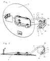
- Fig. 1:
- eine Vereinfachte 3D-Darstellung einer Tankklappe mit integrierter Aufspringmechanik;
- Fig. 2:
- eine Draufsicht auf eine Tankklappe gemäß Figur 1;
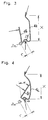
- Fig. 3:
- eine Wirkungsweisendarstellung der Feder bei in entriegeltem Zustand befindlicher Tankklappe;
- Fig. 4:
- eine Wirkungsweisendarstellung der Feder bei in geschlossenem Zustand befindlicher Tankklappe.
- Gemäß Fig. 2 der vorliegenden Zeichung wird die Vorspannung der Blattfeder (1a) durch die Einspannpunkte (3a) und (2b) über den Federschenkel (1b) erhöht, wie dies in den Figuren 3+4 näher dargestellt ist. Das Federende (1b) kann als Biegeschenkel mit einer elastischen Einspannung betrachtet werden. Der Federbereich (1a) erzeugt vorwiegend Druckkräfte, zwischen (2b) und (3a), und kann als Druckstab bezeichnet werden. Dies macht die unterschiedlichen Funktionen der beiden Federenden deutlich. Das Federende (1b) wird im geschlossenen Tankklappenzustand durch den Hebel (4) um den Aufspringwinkel α (sh. Fig. 4) deformiert. Diese zusätzliche Vorspannung bewirkt die gewünschte Aufspringfunktion bei Entriegelung der Tankklappe um einen definierten Winkel. Die entsprechende Abstimmung der Maße x, r sowie Feder und der Scharnierreibung nach der Lackierung verhindert die vollständige Klappenöffnung durch Entriegelung. Die hier zum Einsatz kommende U-Achse (2) dient mit der einen Hälfte (2a) als Verbindungselement zwischen Karosserieteil (3) und Hebel (4) (Scharnierachse) und mit der anderen (2b) als Schwenkachse für die Feder. Alternativ könnte die Federlagerung auch aus dem Hebel (4) ausgebildet werden. Anstelle der Feder könnte hier auch ein anderes Bauteil zum Einsatz kommen, welches Druckkräfte erzeugt und eine zusätzliche Verspannung für die Aufspringmechanik zuläßt.
In der Fig. 3 sind die wirkenden Kräfte auf die Feder im entriegelten Zustand dargestellt. Die Federspannung im Bereich (1a) verursacht eine Drehbewegung der Tankklappe in Richtung des Federschenkels (1b) dies entspricht der Schließrichtung. Die gegenseitige Abstützung des Hebels (4) und der Feder (1b) führt zu einem stabilen Öffnungswinkel.
In der Fig. 4 sind schematisch die wirkenden Kräfte auf die Feder in geschlossenem Zustand der Tankklappe, welcher zugleich der Einbauzustand ist, dargestellt.
Die Kraft F am Hebel ist für die Deformation des Biegeschenkels (1b) um den Winkel α verantwortlich. Diese Vorspannung bewirkt bei Entriegelung eine selbständige Öffnung um den Winkel α.
Claims (8)
- Tankklappe mit integrierter Aufspringmechanik, welche vermittels eines Scharnierarmes und eines Scharnierstiftes in einem am Rand einer Karosseriemulde befestigten Lagerbock schwenkbar gelagert und in ihrer Schließlage mittels einer Verschlußeinrichtung gehalten sowie in Öffnungsrichtung mit einer ständig wirkenden Federlast beaufschlagt ist, wobei die in Öffnungsrichtung wirkende Federlast durch eine gegen den Lagerbock abgestützte Formfeder aufgebracht wird, dadurch gekennzeichnet, daß die Formfeder (1a, 1b) durch eine im Wesentlichen U-förmige Blattfeder gebildet ist und vermittels eines in eine in ihrem Profilgrund ausgebildete Raste eingreifenden radialen Auslegers (2b) des Scharnierstiftes (2a) mit dem Scharnierarm (4) der Tankklappenanlenkung zusammenwirkt.
- Tankklappe nach Anspruch 1, dadurch gekennzeichnet, daß die Blattfeder (1a, 1b) über einen einen ersten Hebel (1a) bildenden und Druckkräfte erzeugenden Federschenkel gegen den Lagerbock (3) der Schwenklagerung der Tankklappe (5) abgestützt ist.
- Tankklappe nach Anspruch 1 und 2, dadurch gekennzeichnet, daß die Blattfeder über einen einen zweiten, eine Vorspanneinrichtung für den ersten Hebel (1a) bildenden Federschenkel (1b) am Scharnierarm (4) anliegt.
- Tankklappe nach Anspruch 1 bis 3, dadurch gekennzeichnet, daß der radiale Ausleger (2b) des Scharnierstiftes (2a) durch den einen Schenkel eines insgesamt als U-förmiges Element ausgebildeten Scharnierstiftes gebildet ist.
- Tankklappe nach Anspruch 1 bis 4, dadurch gekennzeichnet, daß der durch den einen Schenkel (2b) eines insgesamt als U-förmiges Element ausgebildeten Scharnierstiftes gebildete Ausleger des Scharnierstiftes (2a) mit dem Scharnierarm (4) in Mitnehmerverbindung steht.
- Tankklappe nach Anspruch 1 bis 5, dadurch gekennzeichnet, daß die Länge des ersten, Druckkräfte erzeugenden Hebels (1a) und der Abstand des Eingriffes des Auslegers (2b) des Scharnierstiftes (2a) zur Raste im Profilgrund der Blattfeder (1a, 1b) dem für die Aufspringwirkung der Tankklappe (5) erforderlichen Drehmoment entsprechend bemessen sind.
- Tankklappe nach Anspruch 1 bis 6, dadurch gekennzeichnet, daß die Ausrichtung des Auslegers (2b) des Scharnierstiftes (2a) und die Ansrichtung des ersten Federschenkels (1a) der Blattfeder eine Übertotpunktanordnung bilden.
- Tankklappe nach Anspruch 1 dadurch gekennzeichnet, daß anstelle einer Blattfeder ein vergleichbares Bauteil, insbesondere eine Druckfeder eingesetzt ist.
Applications Claiming Priority (2)
| Application Number | Priority Date | Filing Date | Title |
|---|---|---|---|
| DE29608315U DE29608315U1 (de) | 1996-05-08 | 1996-05-08 | Tankklappe mit integrierter Aufspringmechanik |
| DE29608315U | 1996-05-08 |
Publications (2)
| Publication Number | Publication Date |
|---|---|
| EP0806317A1 true EP0806317A1 (de) | 1997-11-12 |
| EP0806317B1 EP0806317B1 (de) | 1999-03-31 |
Family
ID=8023690
Family Applications (1)
| Application Number | Title | Priority Date | Filing Date |
|---|---|---|---|
| EP97106860A Expired - Lifetime EP0806317B1 (de) | 1996-05-08 | 1997-04-25 | Tankklappe mit integrierter Aufspringmechanik |
Country Status (3)
| Country | Link |
|---|---|
| EP (1) | EP0806317B1 (de) |
| DE (2) | DE29608315U1 (de) |
| ES (1) | ES2131977T3 (de) |
Cited By (6)
| Publication number | Priority date | Publication date | Assignee | Title |
|---|---|---|---|---|
| DE19827194A1 (de) * | 1998-06-18 | 1999-12-23 | Volkswagen Ag | Verschlußklappe für eine Tankmulde eines Kraftfahrzeugs |
| DE10023382A1 (de) * | 2000-05-12 | 2001-11-15 | Bayerische Motoren Werke Ag | Tankklappen-Betätigungsvorrichtung |
| DE10133416A1 (de) * | 2001-07-10 | 2003-01-23 | Bayerische Motoren Werke Ag | Kraftfahrzeug mit einer Einfüllöffnung für Kraftstofff |
| FR2871431A1 (fr) | 2004-06-14 | 2005-12-16 | Peugeot Citroen Automobiles Sa | Trappe obturatrice pour une carrosserie d'un vehicule automobile et vehicule automobile comportant une telle trappe |
| WO2019039423A1 (ja) * | 2017-08-25 | 2019-02-28 | 株式会社ニフコ | リッドの付勢構造 |
| CN115605365A (zh) * | 2020-04-08 | 2023-01-13 | 霍富许尔斯贝克和富斯特有限及两合公司(De) | 机动车的加油口盖板系统 |
Families Citing this family (8)
| Publication number | Priority date | Publication date | Assignee | Title |
|---|---|---|---|---|
| GB2330175B (en) * | 1997-10-09 | 1999-12-08 | Itw Ltd | Hinged closures |
| US6367123B1 (en) | 1998-10-09 | 2002-04-09 | Illinois Tool Works Inc. | Vehicle lid hinge |
| DE10064932A1 (de) * | 2000-12-23 | 2002-06-27 | Bayerische Motoren Werke Ag | Vorrichtung zum Abheben einer klappbaren Haube durch mindestens eine Schenkelfeder |
| DE10152699C5 (de) * | 2001-10-19 | 2010-08-12 | Grass Gmbh | Möbelscharnier mit Öffnungsmechanik, insbesondere für Möbeltüren |
| DE20122827U1 (de) | 2001-10-19 | 2008-06-19 | Grass Gmbh | Möbelscharnier mit Öffnungsmechanik, insbesondere für Möbeltüren |
| CN101549641A (zh) * | 2009-05-11 | 2009-10-07 | 奇瑞汽车股份有限公司 | 一种油箱口盖开启机构 |
| DE102012011850A1 (de) | 2012-06-14 | 2013-12-19 | GM Global Technology Operations LLC (n. d. Gesetzen des Staates Delaware) | Tankklappe mit integrierterAufspringautomatik |
| KR102602955B1 (ko) * | 2018-09-21 | 2023-11-16 | 현대자동차주식회사 | 차량용 연료 도어 장치 |
Citations (5)
| Publication number | Priority date | Publication date | Assignee | Title |
|---|---|---|---|---|
| DE7328516U (de) * | 1973-11-15 | Bossert K Druckguss Metallwaren | Anordnung zur Abdeckung einer fur den Tankstutzen eines Kraftfahrzeugs vorgesehenen Karosseneoffnung | |
| DE3212689A1 (de) * | 1982-04-05 | 1983-10-06 | Steffen Kammler | Verschluss fuer den fuellstutzen des kraftstoffbehaelters von kraftfahrzeugen |
| US4527825A (en) * | 1983-11-17 | 1985-07-09 | General Motors Corporation | Fuel filler door with dual hinge |
| US4971382A (en) * | 1988-07-28 | 1990-11-20 | Suzuki Motor Company Limited | Fuel filler door structure for a vehicle |
| WO1991019071A1 (en) * | 1990-06-06 | 1991-12-12 | Itw Limited | Hinge |
-
1996
- 1996-05-08 DE DE29608315U patent/DE29608315U1/de not_active Expired - Lifetime
-
1997
- 1997-04-25 DE DE59700118T patent/DE59700118D1/de not_active Expired - Lifetime
- 1997-04-25 EP EP97106860A patent/EP0806317B1/de not_active Expired - Lifetime
- 1997-04-25 ES ES97106860T patent/ES2131977T3/es not_active Expired - Lifetime
Patent Citations (5)
| Publication number | Priority date | Publication date | Assignee | Title |
|---|---|---|---|---|
| DE7328516U (de) * | 1973-11-15 | Bossert K Druckguss Metallwaren | Anordnung zur Abdeckung einer fur den Tankstutzen eines Kraftfahrzeugs vorgesehenen Karosseneoffnung | |
| DE3212689A1 (de) * | 1982-04-05 | 1983-10-06 | Steffen Kammler | Verschluss fuer den fuellstutzen des kraftstoffbehaelters von kraftfahrzeugen |
| US4527825A (en) * | 1983-11-17 | 1985-07-09 | General Motors Corporation | Fuel filler door with dual hinge |
| US4971382A (en) * | 1988-07-28 | 1990-11-20 | Suzuki Motor Company Limited | Fuel filler door structure for a vehicle |
| WO1991019071A1 (en) * | 1990-06-06 | 1991-12-12 | Itw Limited | Hinge |
Cited By (11)
| Publication number | Priority date | Publication date | Assignee | Title |
|---|---|---|---|---|
| DE19827194A1 (de) * | 1998-06-18 | 1999-12-23 | Volkswagen Ag | Verschlußklappe für eine Tankmulde eines Kraftfahrzeugs |
| DE19827194B4 (de) * | 1998-06-18 | 2012-06-06 | Volkswagen Ag | Verschlußklappe für eine Tankmulde eines Kraftfahrzeugs |
| DE10023382A1 (de) * | 2000-05-12 | 2001-11-15 | Bayerische Motoren Werke Ag | Tankklappen-Betätigungsvorrichtung |
| US6499789B2 (en) | 2000-05-12 | 2002-12-31 | Bayerische Motoren Werke Aktiengesellschaft | Filler inlet compartment lid operating system |
| DE10133416A1 (de) * | 2001-07-10 | 2003-01-23 | Bayerische Motoren Werke Ag | Kraftfahrzeug mit einer Einfüllöffnung für Kraftstofff |
| FR2871431A1 (fr) | 2004-06-14 | 2005-12-16 | Peugeot Citroen Automobiles Sa | Trappe obturatrice pour une carrosserie d'un vehicule automobile et vehicule automobile comportant une telle trappe |
| EP1607261A1 (de) * | 2004-06-14 | 2005-12-21 | Peugeot Citroen Automobiles S.A. | Abdeckklappe für eine Kraftfahrzeugkarrosserie und Kraftfahrzeug mit einer derartigen Abdeckklappe |
| WO2019039423A1 (ja) * | 2017-08-25 | 2019-02-28 | 株式会社ニフコ | リッドの付勢構造 |
| JP2019038369A (ja) * | 2017-08-25 | 2019-03-14 | 株式会社ニフコ | リッドの付勢構造 |
| US11125000B2 (en) | 2017-08-25 | 2021-09-21 | Nifco Inc. | Urging structure for lid |
| CN115605365A (zh) * | 2020-04-08 | 2023-01-13 | 霍富许尔斯贝克和富斯特有限及两合公司(De) | 机动车的加油口盖板系统 |
Also Published As
| Publication number | Publication date |
|---|---|
| DE59700118D1 (de) | 1999-05-06 |
| EP0806317B1 (de) | 1999-03-31 |
| ES2131977T3 (es) | 1999-08-01 |
| DE29608315U1 (de) | 1997-09-04 |
Similar Documents
| Publication | Publication Date | Title |
|---|---|---|
| EP1281558B1 (de) | Tankklappenanordnung für einen Kraftwagen | |
| DE102008064458C5 (de) | Verriegelungsvorrichtung für einen Fahrzeugsitz, Verriegelungsvorrichtungssystem und Verfahren zur Herstellung einer Verriegelungsvorrichtung | |
| DE202004021910U1 (de) | Kraftfahrzeugschloß | |
| EP4166366B1 (de) | Klappeneinheit für eine öffnung an einem fahrzeug und fahrzeug | |
| EP0806317B1 (de) | Tankklappe mit integrierter Aufspringmechanik | |
| EP3973130A1 (de) | Möbelbeschlag | |
| EP2704922B1 (de) | Verriegelungsvorrichtung | |
| EP2705202A1 (de) | Verriegelungsvorrichtung und fahrzeugsitz | |
| DE102005023123A1 (de) | Vorrichtung zum Verhindern der Entriegelung einer Fahrzeugtür | |
| DE102006054753A1 (de) | Elektromechanische Antriebsvorrichtung zum Einsatz in einer Heckklappe eines Kraftfahrzeugs | |
| EP3784855B1 (de) | Kraftfahrzeugschloss | |
| EP1585880B1 (de) | Schliesshilfe zum schliessen einer tür bzw. klappe | |
| EP1267023B1 (de) | Schliesshilfe zum Verschliessen einer Fahrzeugtür | |
| EP1018589B1 (de) | Toleranzausgleich für eine kraftübertragende Verbindung zwischen einem Handgriff und einem Schlossauslösehebel | |
| DE102018113820A1 (de) | Kraftfahrzeugschloss | |
| DE102004045283A1 (de) | Kraftfahrzeugschloß | |
| EP1621710B1 (de) | Scharnier für ein Kraftfahrzeug | |
| WO2020099961A1 (de) | Kraftfahrzeugschloss | |
| DE10008497B4 (de) | Feststellmechanismus für Schiebetür | |
| EP4223964A1 (de) | Schlossanordnung, insbesondere für eine motorhaube eines fahrzeugs | |
| DE102013019378A1 (de) | Verriegelungseinrichtung für ein Flügelelement, insbesondere einen Verdeckkastendeckel, eines Kraftwagens | |
| WO2023246971A1 (de) | KRAFTFAHRZEUG-SCHLIEßVORRICHTUNG | |
| DE10340152A1 (de) | Schloß mit einer Drehfalle und einer Sperrklinke | |
| DE19911589C5 (de) | Fahrzeugsitz, insbesondere Kraftfahrzeugsitz, mit einer Betätigungseinrichtung | |
| EP1388455B1 (de) | Pedalvorrichtung eines Kraftfahrzeugs |
Legal Events
| Date | Code | Title | Description |
|---|---|---|---|
| PUAI | Public reference made under article 153(3) epc to a published international application that has entered the european phase |
Free format text: ORIGINAL CODE: 0009012 |
|
| 17P | Request for examination filed |
Effective date: 19970425 |
|
| AK | Designated contracting states |
Kind code of ref document: A1 Designated state(s): DE ES GB SE |
|
| 17Q | First examination report despatched |
Effective date: 19980402 |
|
| GRAG | Despatch of communication of intention to grant |
Free format text: ORIGINAL CODE: EPIDOS AGRA |
|
| GRAG | Despatch of communication of intention to grant |
Free format text: ORIGINAL CODE: EPIDOS AGRA |
|
| GRAH | Despatch of communication of intention to grant a patent |
Free format text: ORIGINAL CODE: EPIDOS IGRA |
|
| GRAH | Despatch of communication of intention to grant a patent |
Free format text: ORIGINAL CODE: EPIDOS IGRA |
|
| GRAA | (expected) grant |
Free format text: ORIGINAL CODE: 0009210 |
|
| AK | Designated contracting states |
Kind code of ref document: B1 Designated state(s): DE ES GB SE |
|
| GBT | Gb: translation of ep patent filed (gb section 77(6)(a)/1977) |
Effective date: 19990401 |
|
| REF | Corresponds to: |
Ref document number: 59700118 Country of ref document: DE Date of ref document: 19990506 |
|
| REG | Reference to a national code |
Ref country code: ES Ref legal event code: FG2A Ref document number: 2131977 Country of ref document: ES Kind code of ref document: T3 |
|
| PLBE | No opposition filed within time limit |
Free format text: ORIGINAL CODE: 0009261 |
|
| STAA | Information on the status of an ep patent application or granted ep patent |
Free format text: STATUS: NO OPPOSITION FILED WITHIN TIME LIMIT |
|
| 26N | No opposition filed | ||
| REG | Reference to a national code |
Ref country code: GB Ref legal event code: IF02 |
|
| PGFP | Annual fee paid to national office [announced via postgrant information from national office to epo] |
Ref country code: ES Payment date: 20100426 Year of fee payment: 14 |
|
| PGFP | Annual fee paid to national office [announced via postgrant information from national office to epo] |
Ref country code: SE Payment date: 20100415 Year of fee payment: 14 Ref country code: GB Payment date: 20100420 Year of fee payment: 14 Ref country code: DE Payment date: 20100623 Year of fee payment: 14 |
|
| REG | Reference to a national code |
Ref country code: DE Ref legal event code: R082 Ref document number: 59700118 Country of ref document: DE Representative=s name: BONNEKAMP & SPARING, DE Effective date: 20110812 Ref country code: DE Ref legal event code: R081 Ref document number: 59700118 Country of ref document: DE Owner name: EDSCHA ENGINEERING GMBH, DE Free format text: FORMER OWNER: ED. SCHARWAECHTER GMBH, 42855 REMSCHEID, DE Effective date: 20110812 |
|
| REG | Reference to a national code |
Ref country code: DE Ref legal event code: R119 Ref document number: 59700118 Country of ref document: DE |
|
| REG | Reference to a national code |
Ref country code: DE Ref legal event code: R119 Ref document number: 59700118 Country of ref document: DE |
|
| REG | Reference to a national code |
Ref country code: SE Ref legal event code: EUG |
|
| GBPC | Gb: european patent ceased through non-payment of renewal fee |
Effective date: 20110425 |
|
| PG25 | Lapsed in a contracting state [announced via postgrant information from national office to epo] |
Ref country code: GB Free format text: LAPSE BECAUSE OF NON-PAYMENT OF DUE FEES Effective date: 20110425 |
|
| PG25 | Lapsed in a contracting state [announced via postgrant information from national office to epo] |
Ref country code: SE Free format text: LAPSE BECAUSE OF NON-PAYMENT OF DUE FEES Effective date: 20110426 |
|
| REG | Reference to a national code |
Ref country code: ES Ref legal event code: FD2A Effective date: 20130605 |
|
| PG25 | Lapsed in a contracting state [announced via postgrant information from national office to epo] |
Ref country code: DE Free format text: LAPSE BECAUSE OF NON-PAYMENT OF DUE FEES Effective date: 20111031 |
|
| PG25 | Lapsed in a contracting state [announced via postgrant information from national office to epo] |
Ref country code: ES Free format text: LAPSE BECAUSE OF NON-PAYMENT OF DUE FEES Effective date: 20110426 |