EP0806323A1 - Procédé pour tester la fonction du stage de sortie d'un circuit de déclenchement d'un appareil de sécurité - Google Patents
Procédé pour tester la fonction du stage de sortie d'un circuit de déclenchement d'un appareil de sécurité Download PDFInfo
- Publication number
- EP0806323A1 EP0806323A1 EP97107342A EP97107342A EP0806323A1 EP 0806323 A1 EP0806323 A1 EP 0806323A1 EP 97107342 A EP97107342 A EP 97107342A EP 97107342 A EP97107342 A EP 97107342A EP 0806323 A1 EP0806323 A1 EP 0806323A1
- Authority
- EP
- European Patent Office
- Prior art keywords
- switch
- switches
- voltage
- capacitor
- capacitor voltage
- Prior art date
- Legal status (The legal status is an assumption and is not a legal conclusion. Google has not performed a legal analysis and makes no representation as to the accuracy of the status listed.)
- Granted
Links
Images

Classifications
-
- B—PERFORMING OPERATIONS; TRANSPORTING
- B60—VEHICLES IN GENERAL
- B60R—VEHICLES, VEHICLE FITTINGS, OR VEHICLE PARTS, NOT OTHERWISE PROVIDED FOR
- B60R21/00—Arrangements or fittings on vehicles for protecting or preventing injuries to occupants or pedestrians in case of accidents or other traffic risks
- B60R21/01—Electrical circuits for triggering passive safety arrangements, e.g. airbags, safety belt tighteners, in case of vehicle accidents or impending vehicle accidents
- B60R21/017—Electrical circuits for triggering passive safety arrangements, e.g. airbags, safety belt tighteners, in case of vehicle accidents or impending vehicle accidents including arrangements for providing electric power to safety arrangements or their actuating means, e.g. to pyrotechnic fuses or electro-mechanic valves
- B60R21/0173—Diagnostic or recording means therefor
-
- G—PHYSICS
- G05—CONTROLLING; REGULATING
- G05B—CONTROL OR REGULATING SYSTEMS IN GENERAL; FUNCTIONAL ELEMENTS OF SUCH SYSTEMS; MONITORING OR TESTING ARRANGEMENTS FOR SUCH SYSTEMS OR ELEMENTS
- G05B9/00—Safety arrangements
- G05B9/02—Safety arrangements electric
Definitions
- the invention relates to a method for checking the functionality of an output circuit of a trigger circuit of a security system according to the preamble of patent claim 1.
- a very high level of system reliability is required in the case of safety systems, in particular in the case of safety systems in motor vehicles, which comprise personal protection means, such as airbags, belt tensioners and the like.
- safety-critical module units it is required that they are always ready for operation and that, if an error does occur, it is displayed immediately so that the user of a vehicle who trusts the functionality of the safety system does not weigh himself in apparent safety, but immediately can ensure that the safety system is checked and repaired.
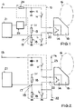
- an output circuit 10 serving as an output stage has an ignition or trigger capacitor 11, which is connected with one connection to a supply voltage input 13 and with its other connection to ground.
- the connection of the trigger capacitor 11 connected to the supply voltage input 13 is connected to ground via a first switch H, a trigger device, for example a squib, and a second switch L, so that when the first and second switches H and L are closed , a trigger current flows through the trigger device 14.
- the trigger device 14 then starts an actuating device 15, for example a gas generator, which inflates an airbag 16 in the case of an airbag system.
- a voltage divider 17 is provided in the output circuit 10, the resistors 18 of which are in series between a predetermined voltage of, for example, 5 V and ground.
- a center tap 19 of the voltage divider 17 is on the one hand with a line 20 lying between the switches H and L and leading to the release device 14 and on the other hand with an input of a test and.
- Evaluation circuit 21 connected.
- Evaluation circuit 21 is part of a trigger circuit or trigger electronics and can for example be integrated in a microprocessor.
- the resistors 18 of the voltage divider 17 are designed so that a voltage Uz at the center tap 19 a defined value, for. B. 2 V, as long as the line 20 is at a floating potential. Because line 20 is normally is separated from the tripping capacitor 11 and from ground by the switches H, L, the line 20 and the tripping device 14 are at the potential predetermined by the voltage Uz at the center tap 19 of the voltage divider 17.
- the line 20 for example arranged in a wiring harness, is considered to be free of errors. So there is neither a faulty connection of line 20 to ground (short to ground) nor a faulty connection of line 20 to a line carrying the battery voltage (connection to U B ).
- step S1 it is first determined in step S1 whether the voltage Uz at the center tap 19 of the voltage divider 17 is equal to the predetermined value, is equal to 2 V. If the voltage Uz is greater or less than the predetermined value 2 V, then there is a connection against the battery voltage U B or against ground and a corresponding error message is generated in step S2. The test routine is then terminated.
- step S1 If it is determined in step S1 that the voltage Uz is equal to the predetermined value, that is to say that the line 20 is rated as error-free, the first switch H is closed in step S3.
- step S4 it is checked whether the voltage Uz is greater than the predetermined value 2 V. If the voltage Uz has not risen, then the switch H has not closed properly and a corresponding error message is generated in step S5. If an increase in the voltage Uz and thus the proper functioning of the first switch H were found in step S4, the following step shows S6 the first switch H is opened again. This also occurs if, despite an error message in step S5, the second switch is to be checked.
- step S6 After opening the first switch H in step S6, the second switch L is closed in step S7 and it is checked in step S8 whether the voltage Uz is less than the predetermined value 2V. If this is the case, the second switch L has closed without errors. Thus, after opening switch L, the test routine can be ended in step S9. If, when checking the voltage Uz with the second switch L closed, it is found that the voltage does not almost correspond to the ground potential, an error message is generated in step S10, which indicates that the second switch L is not closing properly.
- the object of the invention is a further method for checking the functionality of a To provide the output circuit of a trigger circuit of a security system, in particular the risk of false tripping is further reduced or excluded.
- the switches in the output circuit are therefore not checked at any point in time after the safety system is switched on, but immediately after the switch on, before the ignition or release capacitor is charged.
- the switches that keep the triggering device at a floating potential they are closed as long as the voltage at the triggering capacitor is still so low that the current caused by the triggering device is not sufficient to trigger it.
- false triggering due to a sporadic or permanent presence of a short to ground shorting the switch located between the triggering device and ground is reliably prevented.
- Another advantage of the method according to the invention is that even output circuits which have only one switch can be checked for the functionality of the switch without the risk of false triggering.
- the safety of the method according to the invention can be further increased by ascertaining before the switches are checked whether the capacitor voltage has not yet exceeded a maximum permissible value. This avoids false triggers when testing the switches, which could occur if the capacitor is not yet fully discharged when the safety system is switched on or if the capacitor has been charged too quickly due to a fault in the charging circuit.
- the capacitor voltage in the case of closed switches is expediently compared with the capacitor voltage that existed before the switches were closed in order to detect a discharge of the trigger capacitor, which was only slightly charged, and in this way to check the conductivity of the closed switches.
- a comparative value for the capacitor voltage present when the switches are closed can expediently be specified for this purpose, which can be determined in particular from the capacitor voltage before the switches are closed.
- the checking of the tripping capacitor can also be easily integrated into the corresponding test routine. For this purpose, in particular after the two switches have been opened or, if only one is present, the switch and the waiting time has elapsed, the capacitor voltage is detected again and compared with the corresponding setpoint.
- the current flowing through the tripping device is limited to a value which is smaller than the permissible test current for the tripping device.
- an output circuit 10 of a safety system has an ignition or release capacitor 11, one connection of which is connected to ground via a charging resistor 24 to a supply voltage input 13 and a series circuit comprising a first switch H, a release device 14 and a second switch L. .
- the other connection of the capacitor 11 is directly to ground.
- a voltage divider 17, the resistors of which are in series between a fixed voltage, for example 5 V, and ground, is provided with its center tap 19 with a line 20 leading to the triggering device 14 and with an input of a test circuit integrated in particular in a triggering circuit or electronics. and evaluation circuit 21 connected, so that after checking the switches H, L while the security system is in standby, the line 20 can be checked continuously for connections.
- this capacitor terminal is connected to the test and evaluation circuit 21 via a converter circuit 25, which can be designed, for example, as a voltage divider.
- the corresponding test routine is started immediately after the safety system is switched on.
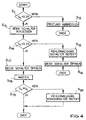
- the start of the test routine - as shown in FIG. 4 - it is checked in step S11 whether the capacitor voltage U K is less than a predetermined value, for example 0.3 V. If this is not the case because the trigger capacitor 11 has not yet been completely discharged or has already been charged to a higher level, the test is terminated in step S12. The test routine is then ended. If, as expected, the capacitor voltage U K is smaller than the predetermined value, both switches H, L are closed in step S13. The capacitor voltage U K is then measured again in step S14 and compared with a second value, which may be 0.2 V, for example.
- a predetermined value for example 0.3 V
- a comparison value from the determined in step S11 capacitor voltage can be calculated, is decreased in the example, the value determined in step S11 of the capacitor voltage U K to 0.1 V.
- the checked capacitor voltage U K shows in step S14 that it has not decreased in the desired manner or is greater than an allowable limit value, e.g. B. can be set according to a maximum permissible test current for the triggering device, an error message is generated in step S15, which indicates that an error has occurred in the switches H, L. Then both switches are opened in step S16, in order to then end the test routine.
- step S14 If it is determined in step S14 that the capacitor voltage has dropped in the desired manner, both switches are then opened again in step S17 and a waiting time is started in step S18, after which the capacitor voltage U K with the target voltage has expired in step S19 U S is compared. If the comparison of step S19 shows that the capacitor voltage U K is approximately equal to the target voltage U S , the test routine for testing the output circuit, in particular for testing the switches H, L, is ended. However, if the capacitor voltage U K has not reached the required level after the waiting time from step S18, an error message is output in step S20, which indicates that the trigger capacitor 11 or its charging circuit is defective.
- switches H, L are checked immediately after the safety system is switched on, at a point in time at which the capacitor voltage U K has not yet exceeded a sufficiently small value and since the charging current for the tripping capacitor 11 is limited to a value by means of the charging resistor 24 , which ensures that when switches H, L are closed and the discharge capacitor 11 is practically uncharged, the current through the release device 14 is less than the permissible test current for the release device 14, both switches H, L can be tested simultaneously, with sporadically occurring ground faults in the off Line 20 and trigger device 14 formed ignition or trigger circuit can not lead to false triggering.
- Another advantage of the method according to the invention is that even in security systems which have only one switch in the output circuit 10, the functionality of this one switch can be checked simply and reliably.
Landscapes
- Engineering & Computer Science (AREA)
- Physics & Mathematics (AREA)
- General Physics & Mathematics (AREA)
- Automation & Control Theory (AREA)
- Mechanical Engineering (AREA)
- Air Bags (AREA)
- Driving Mechanisms And Operating Circuits Of Arc-Extinguishing High-Tension Switches (AREA)
- Keying Circuit Devices (AREA)
Applications Claiming Priority (2)
| Application Number | Priority Date | Filing Date | Title |
|---|---|---|---|
| DE19619118 | 1996-05-11 | ||
| DE19619118A DE19619118C1 (de) | 1996-05-11 | 1996-05-11 | Verfahren zur Überprüfung der Funktionsfähigkeit eines Ausgangsschaltkreises einer Auslöseschaltung eines Sicherheitssystems |
Publications (2)
| Publication Number | Publication Date |
|---|---|
| EP0806323A1 true EP0806323A1 (fr) | 1997-11-12 |
| EP0806323B1 EP0806323B1 (fr) | 1999-02-24 |
Family
ID=7794097
Family Applications (1)
| Application Number | Title | Priority Date | Filing Date |
|---|---|---|---|
| EP97107342A Expired - Lifetime EP0806323B1 (fr) | 1996-05-11 | 1997-05-03 | Procédé pour tester la fonction du stage de sortie d'un circuit de déclenchement d'un appareil de sécurité |
Country Status (3)
| Country | Link |
|---|---|
| EP (1) | EP0806323B1 (fr) |
| DE (2) | DE19619118C1 (fr) |
| ES (1) | ES2130862T3 (fr) |
Cited By (3)
| Publication number | Priority date | Publication date | Assignee | Title |
|---|---|---|---|---|
| EP0947397A3 (fr) * | 1998-04-04 | 2000-04-12 | DaimlerChrysler AG | Méthode pour contrôler l' opération d' un système de protection de passager ainsi que le circuit de contrôle pour la mise en oeuvre de cette technique |
| EP0979761A3 (fr) * | 1998-08-10 | 2000-10-25 | Breed Automotive Technology, Inc. | Unité de commande pour un prétensionneur |
| EP0999956B1 (fr) * | 1997-07-29 | 2002-03-27 | Siemens Aktiengesellschaft | Dispositif et procede pour essayer un montage servant a commander un moyen de protection d'occupant d'un vehicule automobile |
Families Citing this family (2)
| Publication number | Priority date | Publication date | Assignee | Title |
|---|---|---|---|---|
| DE19922818A1 (de) * | 1999-05-19 | 2000-11-23 | Nokia Mobile Phones Ltd | Verfahren zur Überprüfung einer Auswerteschaltung |
| DE10147884A1 (de) * | 2001-09-28 | 2003-04-24 | Infineon Technologies Ag | Steuervorrichtung für ein Insassenschutzmittel |
Citations (5)
| Publication number | Priority date | Publication date | Assignee | Title |
|---|---|---|---|---|
| DE3920713A1 (de) * | 1989-06-24 | 1991-01-10 | Bosch Gmbh Robert | Insassen-sicherheitseinrichtung fuer fahrzeuge |
| US5134306A (en) * | 1988-09-09 | 1992-07-28 | Robert Bosch Gmbh | Detonation circuit for a vehicle air bag |
| US5176214A (en) * | 1989-07-08 | 1993-01-05 | Robert Bosch Gmbh | Safety system for motor-vehicle occupants |
| EP0590180A1 (fr) * | 1992-09-29 | 1994-04-06 | Siemens Aktiengesellschaft | Dispositif de mesure pour tester les connexions de masse d'une commande, par exemple commande d'un système d'airbag d'un véhicule |
| US5389822A (en) * | 1990-05-23 | 1995-02-14 | Messerschmitt-Bolkow-Blohm Gmbh | Triggering circuit for a safety device in motor vehicles |
Family Cites Families (2)
| Publication number | Priority date | Publication date | Assignee | Title |
|---|---|---|---|---|
| JPH01274628A (ja) * | 1988-04-25 | 1989-11-02 | Nippon Denso Co Ltd | 乗員保護装置の異常判定装置 |
| DE4220904A1 (de) * | 1992-06-25 | 1994-01-05 | Messerschmitt Boelkow Blohm | Verfahren zur Prüfung mechanischer Schalter in Sicherheitssystemen von Kraftfahrzeugen |
-
1996
- 1996-05-11 DE DE19619118A patent/DE19619118C1/de not_active Expired - Fee Related
-
1997
- 1997-05-03 ES ES97107342T patent/ES2130862T3/es not_active Expired - Lifetime
- 1997-05-03 EP EP97107342A patent/EP0806323B1/fr not_active Expired - Lifetime
- 1997-05-03 DE DE59700092T patent/DE59700092D1/de not_active Expired - Lifetime
Patent Citations (5)
| Publication number | Priority date | Publication date | Assignee | Title |
|---|---|---|---|---|
| US5134306A (en) * | 1988-09-09 | 1992-07-28 | Robert Bosch Gmbh | Detonation circuit for a vehicle air bag |
| DE3920713A1 (de) * | 1989-06-24 | 1991-01-10 | Bosch Gmbh Robert | Insassen-sicherheitseinrichtung fuer fahrzeuge |
| US5176214A (en) * | 1989-07-08 | 1993-01-05 | Robert Bosch Gmbh | Safety system for motor-vehicle occupants |
| US5389822A (en) * | 1990-05-23 | 1995-02-14 | Messerschmitt-Bolkow-Blohm Gmbh | Triggering circuit for a safety device in motor vehicles |
| EP0590180A1 (fr) * | 1992-09-29 | 1994-04-06 | Siemens Aktiengesellschaft | Dispositif de mesure pour tester les connexions de masse d'une commande, par exemple commande d'un système d'airbag d'un véhicule |
Cited By (4)
| Publication number | Priority date | Publication date | Assignee | Title |
|---|---|---|---|---|
| EP0999956B1 (fr) * | 1997-07-29 | 2002-03-27 | Siemens Aktiengesellschaft | Dispositif et procede pour essayer un montage servant a commander un moyen de protection d'occupant d'un vehicule automobile |
| EP0947397A3 (fr) * | 1998-04-04 | 2000-04-12 | DaimlerChrysler AG | Méthode pour contrôler l' opération d' un système de protection de passager ainsi que le circuit de contrôle pour la mise en oeuvre de cette technique |
| US6218739B1 (en) | 1998-04-04 | 2001-04-17 | Daimlerchrysler Ag | Procedure for the functional testing of a vehicle occupant protection system as well as a test circuit for implementing the procedure |
| EP0979761A3 (fr) * | 1998-08-10 | 2000-10-25 | Breed Automotive Technology, Inc. | Unité de commande pour un prétensionneur |
Also Published As
| Publication number | Publication date |
|---|---|
| EP0806323B1 (fr) | 1999-02-24 |
| ES2130862T3 (es) | 1999-07-01 |
| DE59700092D1 (de) | 1999-04-01 |
| DE19619118C1 (de) | 1997-10-02 |
Similar Documents
| Publication | Publication Date | Title |
|---|---|---|
| EP0691244B1 (fr) | Méthode de test pour un dispositif de sécurité dans des véhicules automobiles | |
| DE69100137T2 (de) | Einrichtung zum Erfassen des Vorhandenseins einer Ungewöhnlichkeit in einem Fahrzeuginsassen-Schutzsystem. | |
| DE3913628C2 (de) | Vorrichtung zur Ermittlung des Vorliegens einer Unregelmäßigkeit in einem Fahrzeugbenutzerschutzsystem | |
| DE2454424C3 (de) | Schaltung für einen elektronischen Sensor zur Auslösung einer Sicherheitsvorrichtung | |
| EP0301442B1 (fr) | Circuit pour la supervision de fils vers un interrupteur ou un détecteur | |
| EP0478564B1 (fr) | Dispositif de securite pour les passagers d'un vehicule | |
| DE2851333A1 (de) | Pruefschaltung fuer die ausloesevorrichtung einer den schutz der insassen eines fahrzeugs waehrend eines unfalles dienenden sicherheitseinrichtung | |
| DE19950008A1 (de) | Verfahren und Anordnung zum Steuern des Schaltzustands einer Schaltverbindung zwischen den elektrischen Ausgängen einer in einer mobilen Vorrichtung angeordneten Brennstoffzelle und einem in der mobilen Vorrichtung angeordneten isolierten elektrischen Netz | |
| DE3400533C2 (de) | Auslösevorrichtung für Sicherheitsvorrichtungen in Fahrzeugen | |
| WO1996009191A1 (fr) | Dispositif electronique de securite pour passagers de vehicules | |
| DE3506487C2 (de) | Spannungsversorgungseinrichtung für eine Insassenschutzvorrichtung in einem Fahrzeug | |
| EP0629161B1 (fr) | Circuit de declenchement du systeme de protection d'un vehicule automobile commande par un detecteur de collision | |
| EP0515977A2 (fr) | Ballast électronique pour lampe à décharge haute-pression utilisée dans l'automobile | |
| DE102004057694A1 (de) | Bordnetz mit höherer Spannung | |
| EP0961383A1 (fr) | Méthode et dispositif pour tester la capacité d'un condensateur de stockage dans un système de protection de passagers | |
| EP0482015B1 (fr) | Dispositif de securite pour les occupants d'un vehicule | |
| WO2018108514A1 (fr) | Véhicule automobile à moteur électrique, notamment véhicule hybride ou électrique | |
| EP0806323B1 (fr) | Procédé pour tester la fonction du stage de sortie d'un circuit de déclenchement d'un appareil de sécurité | |
| WO1991005680A1 (fr) | Circuit pour le declenchement d'un systeme de protection pour les occupants d'un vehicule | |
| EP0732793B1 (fr) | Dispositif de circuit, spécialement pour systèmes critiques pour la sécurité dans des véhicules pour transport de personnes | |
| WO1999059843A1 (fr) | Procede et dispositif pour verifier un circuit electrique, notamment le circuit d'allumage d'un systeme de protection des occupants d'une automobile | |
| DE19749856B4 (de) | Verfahren und Zündschaltung zur Auslösung eines Insassenschutzsystems | |
| EP0980005B1 (fr) | Procédé et circuit pour le test fonctionnel d'un circuit d'allumage pour un système de protection de passagers | |
| EP1220768B1 (fr) | Dispositif d'allumage pour un dispositif pyrotechnique de protection des occupants | |
| DE102021113213A1 (de) | Bordnetz, Kraftfahrzeug und Verfahren zum Durchführen einer Isolationsprüfung |
Legal Events
| Date | Code | Title | Description |
|---|---|---|---|
| PUAI | Public reference made under article 153(3) epc to a published international application that has entered the european phase |
Free format text: ORIGINAL CODE: 0009012 |
|
| AK | Designated contracting states |
Kind code of ref document: A1 Designated state(s): DE ES FR GB IT SE |
|
| 17P | Request for examination filed |
Effective date: 19971014 |
|
| 17Q | First examination report despatched |
Effective date: 19971218 |
|
| GRAG | Despatch of communication of intention to grant |
Free format text: ORIGINAL CODE: EPIDOS AGRA |
|
| GRAG | Despatch of communication of intention to grant |
Free format text: ORIGINAL CODE: EPIDOS AGRA |
|
| GRAH | Despatch of communication of intention to grant a patent |
Free format text: ORIGINAL CODE: EPIDOS IGRA |
|
| GRAH | Despatch of communication of intention to grant a patent |
Free format text: ORIGINAL CODE: EPIDOS IGRA |
|
| GRAA | (expected) grant |
Free format text: ORIGINAL CODE: 0009210 |
|
| AK | Designated contracting states |
Kind code of ref document: B1 Designated state(s): DE ES FR GB IT SE |
|
| ITF | It: translation for a ep patent filed | ||
| GBT | Gb: translation of ep patent filed (gb section 77(6)(a)/1977) |
Effective date: 19990224 |
|
| REF | Corresponds to: |
Ref document number: 59700092 Country of ref document: DE Date of ref document: 19990401 |
|
| ET | Fr: translation filed | ||
| REG | Reference to a national code |
Ref country code: ES Ref legal event code: FG2A Ref document number: 2130862 Country of ref document: ES Kind code of ref document: T3 |
|
| PLBE | No opposition filed within time limit |
Free format text: ORIGINAL CODE: 0009261 |
|
| STAA | Information on the status of an ep patent application or granted ep patent |
Free format text: STATUS: NO OPPOSITION FILED WITHIN TIME LIMIT |
|
| 26N | No opposition filed | ||
| REG | Reference to a national code |
Ref country code: GB Ref legal event code: IF02 |
|
| PGFP | Annual fee paid to national office [announced via postgrant information from national office to epo] |
Ref country code: DE Payment date: 20120523 Year of fee payment: 16 |
|
| PGFP | Annual fee paid to national office [announced via postgrant information from national office to epo] |
Ref country code: SE Payment date: 20120522 Year of fee payment: 16 Ref country code: GB Payment date: 20120522 Year of fee payment: 16 Ref country code: FR Payment date: 20120601 Year of fee payment: 16 |
|
| PGFP | Annual fee paid to national office [announced via postgrant information from national office to epo] |
Ref country code: IT Payment date: 20120531 Year of fee payment: 16 |
|
| PGFP | Annual fee paid to national office [announced via postgrant information from national office to epo] |
Ref country code: ES Payment date: 20120525 Year of fee payment: 16 |
|
| REG | Reference to a national code |
Ref country code: SE Ref legal event code: EUG |
|
| GBPC | Gb: european patent ceased through non-payment of renewal fee |
Effective date: 20130503 |
|
| PG25 | Lapsed in a contracting state [announced via postgrant information from national office to epo] |
Ref country code: SE Free format text: LAPSE BECAUSE OF NON-PAYMENT OF DUE FEES Effective date: 20130504 Ref country code: DE Free format text: LAPSE BECAUSE OF NON-PAYMENT OF DUE FEES Effective date: 20131203 |
|
| PG25 | Lapsed in a contracting state [announced via postgrant information from national office to epo] |
Ref country code: IT Free format text: LAPSE BECAUSE OF NON-PAYMENT OF DUE FEES Effective date: 20130503 |
|
| REG | Reference to a national code |
Ref country code: DE Ref legal event code: R119 Ref document number: 59700092 Country of ref document: DE Effective date: 20131203 |
|
| REG | Reference to a national code |
Ref country code: FR Ref legal event code: ST Effective date: 20140131 |
|
| PG25 | Lapsed in a contracting state [announced via postgrant information from national office to epo] |
Ref country code: GB Free format text: LAPSE BECAUSE OF NON-PAYMENT OF DUE FEES Effective date: 20130503 |
|
| PG25 | Lapsed in a contracting state [announced via postgrant information from national office to epo] |
Ref country code: FR Free format text: LAPSE BECAUSE OF NON-PAYMENT OF DUE FEES Effective date: 20130531 |
|
| REG | Reference to a national code |
Ref country code: ES Ref legal event code: FD2A Effective date: 20140606 |
|
| PG25 | Lapsed in a contracting state [announced via postgrant information from national office to epo] |
Ref country code: ES Free format text: LAPSE BECAUSE OF NON-PAYMENT OF DUE FEES Effective date: 20130504 |