EP0806346A2 - Machine d'emballage équipée d'un système pour former un tube - Google Patents
Machine d'emballage équipée d'un système pour former un tube Download PDFInfo
- Publication number
- EP0806346A2 EP0806346A2 EP97106684A EP97106684A EP0806346A2 EP 0806346 A2 EP0806346 A2 EP 0806346A2 EP 97106684 A EP97106684 A EP 97106684A EP 97106684 A EP97106684 A EP 97106684A EP 0806346 A2 EP0806346 A2 EP 0806346A2
- Authority
- EP
- European Patent Office
- Prior art keywords
- edges
- tube
- film
- packaging machine
- mold
- Prior art date
- Legal status (The legal status is an assumption and is not a legal conclusion. Google has not performed a legal analysis and makes no representation as to the accuracy of the status listed.)
- Granted
Links
Images


Classifications
-
- B—PERFORMING OPERATIONS; TRANSPORTING
- B65—CONVEYING; PACKING; STORING; HANDLING THIN OR FILAMENTARY MATERIAL
- B65B—MACHINES, APPARATUS OR DEVICES FOR, OR METHODS OF, PACKAGING ARTICLES OR MATERIALS; UNPACKING
- B65B59/00—Arrangements to enable machines to handle articles of different sizes, to produce packages of different sizes, to vary the contents of packages, to handle different types of packaging material, or to give access for cleaning or maintenance purposes
- B65B59/02—Arrangements to enable adjustments to be made while the machine is running
-
- B—PERFORMING OPERATIONS; TRANSPORTING
- B65—CONVEYING; PACKING; STORING; HANDLING THIN OR FILAMENTARY MATERIAL
- B65B—MACHINES, APPARATUS OR DEVICES FOR, OR METHODS OF, PACKAGING ARTICLES OR MATERIALS; UNPACKING
- B65B57/00—Automatic control, checking, warning, or safety devices
- B65B57/10—Automatic control, checking, warning, or safety devices responsive to absence, presence, abnormal feed, or misplacement of articles or materials to be packaged
- B65B57/12—Automatic control, checking, warning, or safety devices responsive to absence, presence, abnormal feed, or misplacement of articles or materials to be packaged and operating to control, or stop, the feed of wrapping materials, containers, or packages
-
- B—PERFORMING OPERATIONS; TRANSPORTING
- B65—CONVEYING; PACKING; STORING; HANDLING THIN OR FILAMENTARY MATERIAL
- B65B—MACHINES, APPARATUS OR DEVICES FOR, OR METHODS OF, PACKAGING ARTICLES OR MATERIALS; UNPACKING
- B65B59/00—Arrangements to enable machines to handle articles of different sizes, to produce packages of different sizes, to vary the contents of packages, to handle different types of packaging material, or to give access for cleaning or maintenance purposes
- B65B59/001—Arrangements to enable adjustments related to the product to be packaged
-
- B—PERFORMING OPERATIONS; TRANSPORTING
- B65—CONVEYING; PACKING; STORING; HANDLING THIN OR FILAMENTARY MATERIAL
- B65B—MACHINES, APPARATUS OR DEVICES FOR, OR METHODS OF, PACKAGING ARTICLES OR MATERIALS; UNPACKING
- B65B59/00—Arrangements to enable machines to handle articles of different sizes, to produce packages of different sizes, to vary the contents of packages, to handle different types of packaging material, or to give access for cleaning or maintenance purposes
- B65B59/003—Arrangements to enable adjustments related to the packaging material
-
- B—PERFORMING OPERATIONS; TRANSPORTING
- B65—CONVEYING; PACKING; STORING; HANDLING THIN OR FILAMENTARY MATERIAL
- B65B—MACHINES, APPARATUS OR DEVICES FOR, OR METHODS OF, PACKAGING ARTICLES OR MATERIALS; UNPACKING
- B65B9/00—Enclosing successive articles, or quantities of material, e.g. liquids or semiliquids, in flat, folded, or tubular webs of flexible sheet material; Subdividing filled flexible tubes to form packages
- B65B9/06—Enclosing successive articles, or quantities of material, in a longitudinally-folded web, or in a web folded into a tube about the articles or quantities of material placed upon it
- B65B2009/063—Forming shoulders
Definitions
- the present invention relates to a packaging machine for packaging objects in a film, with a tube forming device for forming a tube from a film which is essentially flat before tube forming, and a transport device for transporting the objects into the tube, the tube forming device having a plurality of pairs of shaped edges for deflection the film has.
- a packaging machine of the type mentioned is known from DE 40 21 934 A1.
- the tube forming device has a plurality of guide plates, which essentially have three pairs of shaped edges, around which the film is guided one after the other.
- a first wing-like guide plate feeds the packaging film obliquely downward against the transport direction of the objects to be packaged, the film being deflected by means of the first guide plate and two further guide plates arranged in scissors and formed into a tube which runs in the transport direction of the objects to be packaged.
- the individual shaped edges of the guide plates are arranged relative to one another in such a way that the film is independent of the form edge or the area of the guide plates it runs, is evenly tensioned and even, ie runs over the edges without torsion. Form edges overlapped by the film lie in pairs in a common plane.
- the present invention is therefore based on the object of specifying a packaging machine with an improved tube forming device of the type mentioned at the outset.
- excessive stress on the film should be avoided and overstretching of the film should be prevented.
- the film is guided over the mold edges in such a way that the edges of the film run tension-free or loosely over the mold edges. This has the advantage that the film is protected at the edges from excessive tension and overstretching.
- the film runs wrinkle-free over the tube forming device despite the non-constant tension distribution. So far it has always been assumed that the path over the mold edges parallel to the edges of the film must be of the same length for all areas of the film in order to prevent that the film converges towards its central area and accordingly folds. However, the opposite is the case.
- the foil that is guided or drawn over the edges of the mold tries to run over the edges of the mold in the shortest possible way and is tightened very slightly across the longitudinal direction of the foil towards the edges, so that no folds occur.
- the film or parts thereof run successively over first mold edges of a first mold shoulder and second and third mold edges of a second mold shoulder.
- first mold edges and an associated one, i.e. second mold edge overrun by the same piece of film, not in one plane.
- shape edges of the same pair of shape edges can lie in a common plane.
- Edges overlapped one after the other by the film are thus skewed to one another. So far it has been assumed that the edges of the film which have been overrun one after the other must lie in one plane in order to guide the film without folds and evenly stretched over the edges of the tube forming device.
- one of the first mold edges and an associated second mold edge are in each case arranged relative to one another in such a way that the film is interlaced between the respectively associated first and second mold edges. This has the advantage that the film is guided gently and loosely over the edges of the mold.
- the first shape shoulder can be separated from the second shape shoulder, ie it cannot be connected to it, and is expediently arranged above the second shape shoulder.
- the first shape shoulder is preferably designed as a trapezoidal, in particular multi-piece sheet metal part and the second shape shoulder, which is essentially in the transport plane the transport device, has two substantially triangular pieces of sheet metal, which overlap each other in a scissor-like manner, such that the third mold edges converge and overlap in the hose exit direction and that the second mold edges diverge in the hose exit direction.
- the shape shoulders can be made of different materials, but the shape shoulders in sheet metal construction have advantages in terms of a simple and stable design.
- the shaped shoulders can also be designed in a frame-like manner in such a way that only the shaped edges are provided in the manner of ribs, but the plate-shaped sheet metal construction has advantages with regard to a uniform and smoothly sliding film guide.
- the angular orientation of at least one of the pairs of mold edges, in particular the first mold edges is adjustable.
- the degree of entanglement of the film running over the form edges and the amount of the distance difference between the areas in which the edge of the film runs and the area in which a central section of the film runs over the form edges can be set.
- the stress distribution in the film and the belly which the film has on the film edges between successive mold edges can be adjusted.
- the adjustability of the angular alignment of at least individual shaped edges has the advantage that the geometry of the tube shaping device is based on different foils of different thicknesses and made of different materials can be adjusted.
- the angular orientation can also be adjusted as a function of the size of the objects to be packaged in order to optimally pull the film over the tube shaping device in the case of different objects which require a different tube geometry and different overlap widths. In particular, it can be adjusted to what extent the edge of the film runs loosely over the mold edges and the tension in the film is distributed differently.
- the corresponding adjustable mold edges have an adjustment range such that these mold edges do not lie in one plane with the respectively associated mold edges of the next pair of mold edges and that there is always an entanglement of the film guided over the mold edges and the edge regions of the film are guided stress-free and loosely.
- the shaped edges are expediently pivotable in a common plane.
- the angle of the mold edges to one another in this plane is therefore adjustable.
- the first shape shoulder preferably has two sheets which are arranged in a common plane and each have a first shape edge, the sheets being pivotable about an axis perpendicular to the common plane. The sheets can thus be swiveled in the plane that you define yourself.
- the first mold shoulder can also be pivoted as a whole about a substantially horizontal axis, as a result of which the effective angle of the first mold edges can be adjusted relative to the second mold edges, but the embodiment described above has advantages with regard to simple pivoting mounting of the mold shoulder plates.
- the first and second mold edges each intersect at one point in their extension, the first mold edges being more widely spread than the second mold edges.
- the orientation of the mold edges is preferably such that the projection of the angle enclosed between the first mold edges into the plane of the second mold edges is greater than the angle which is limited between the second mold edges.
- the mold edges can be translationally displaceable, the mold edges preferably being displaceable in pairs in opposite directions and at least one pair of the mold edges being displaceable relative to the other mold edges, in particular in such a way that a height and a width of the tube formed from the film can be adjusted.
- the objects which are to be packaged are conventionally delivered on the side of the tube forming device which is opposite the side on which the film formed into the tube runs out of the tube forming device and through the tube forming device between the shaping shoulders transported in the draining hose. It is known to feed the transport device or, in the case of a multi-piece design of the transport device, a portion of the same into the hose-forming device in order to be able to transport the corresponding object into the draining hose over the shaped sheets.
- this known embodiment is structurally relatively complicated and economically unsatisfactory.
- a packaging machine is provided with an improved transport device, in which in particular the transport device reliably transports objects of different sizes even with different settings of the tube forming device into the tube formed from the film effect. For this purpose, the position of a downstream end of the transport device can be adjusted.
- No transport device is provided in the area of the tube forming device itself and the objects are transported indirectly through the film itself in the area of the tube forming device.
- the downstream end of the transport device is adjustable such that the objects to be transported can always be brought directly up to the hose forming device even with different settings of the hose forming device and can be pushed onto the film running in the hose forming device. There is no or only a minimal gap between the end of the transport device and the tube forming device, which gap could hinder the forward movement of the object to be transported.
- the downstream end of the transport device can preferably be set synchronously with the movable shaping shoulder of the hose shaping device.
- the adjustable end of the transport device is thus coupled to the movable mold shoulder in such a way that when the mold shoulder is adjusted, for example for different geometries of the objects to be packaged, the transport device is adjusted automatically and in such a way that the end of the transport device ends directly on the mold shoulder and there is no larger gap between the transport device and the form shoulder.
- an effective transport path of the transport device is adjustable in length. This has the advantage that the upstream end of the transport device can be arranged in a stationary manner, in particular following a feed for the objects, and at the same time the Position of the downstream end of the transport device is adjustable.
- the downstream end of the transport device is adapted to an opposite contour of the hose shaping device, wherein preferably a front edge of the hose shaping device, over which the objects are pushed into the hose shaping device, is V-shaped and the downstream end of the transport device is tongue-shaped into the V-shaped one Recess of the hose forming device extends.
- the downstream end of the transport device can be moved back and forth in the transport direction in such a way that the complementary V-shaped end of the transport device moves back when the V-shaped opening of the hose forming device is scissor-like is narrowed to set a smaller width of the tube formed from the film.
- the transport device has at least one endless conveying means rotating around deflecting means, the conveying means being guided around a displaceable deflecting unit at the downstream end of the conveying device.
- the displaceable deflection unit via which the conveying means is guided in an S-shape, is arranged between two fixed deflecting means and can be moved back and forth parallel to the straight sections of the conveying means between the deflecting unit and the two fixed deflecting means.
- the conveyor can be pre-tensioned without a special tensioning device such as tensioning rollers.
- a length adjustment of the conveying path, ie a displacement of the deflection unit can be effected without changing the length of the path covered by the conveying means.
- the funding advantageously has one uniform tension that is not affected by inertial effects such as a dancer roller commonly used to tension endless belts.
- the transport device preferably has a plurality of narrow conveyor belts running in parallel, the conveyor belts preferably being guided at the downstream end of the transport device around rollers which are offset in steps, such that the downstream end is adapted in stages to the V-shaped front side of the tube-forming device.
- the rollers can be mounted on a common, displaceable carriage and can be displaced synchronously with one another parallel to the conveying direction.
- a removal device for removing the objects wrapped in the hose connects to an outlet side of the hose forming device essentially flush with the latter.
- the removal device preferably has a suction belt conveyor, in which the objects wrapped in the hose are sucked onto a conveyor belt.
- the suction also causes the hose running out of the hose molding device to be transported if no objects are enclosed therein.
- the suction causes the hose to adhere to the conveyor belt.
- the discharge device could also provide an electrostatic attraction of the film to the conveyor belt, but the suction of the draining hose has advantages in terms of stable static friction between the film and the conveyor belt, in particular also with different films.
- an automatically adjustable packaging machine is created, in particular an adjusting device for adjusting the tube shaping device for different objects to be packaged and a control device for controlling the adjusting device as a function of object parameters, e.g. Length, width and height etc. of the object are provided.
- the object parameters can, for example, be entered manually using a corresponding input unit.
- the packaging machine preferably has a memory device for storing the object parameters assigned to each object, the control device reading the corresponding object parameters from the memory device by means of a reading unit and controlling the setting device as a function of these stored parameters.
- an input unit is provided with which the object to be packaged can be input.
- the control device then reads the object parameters assigned to this object from the storage device in order to control the setting device accordingly.
- a detection device could also be provided, with the aid of which the object to be packaged is automatically detected. According to the result of the automatic detection, the respective object parameters are then read from the memory in order to control the setting device.
- An evaluation unit can be connected downstream of the detection device to evaluate which stored object the detected object corresponds to or comes closest to.
- the adjusting device can have a plurality of servomotors, each of which is assigned to different axes of movement of the tube shaping device and is controlled by the control device.
- Servomotors are preferably assigned to both the translatory displacement axes and the angular adjustment axes of the tube shaping device.
- Stepper motors can be used as servomotors, an indirect displacement measurement being provided by counting the step pulses.
- Servomotors can also be provided, it being possible for direct displacement measurement by means of pulse generators and evaluation in a suitable controller to be provided.
- the adjusting device is preferably coupled to the transport device.
- the transport device is therefore also automatically adapted to the object to be packed and the corresponding setting of the tube forming device.
- Downstream units such as a film sealing device, can also be controlled by the control device.
- a completely automatic setting of the packaging machine is thus effected by entering or recording the object to be packaged.
- the control device described can also particularly advantageously simplify the setting up of the tube shaping device for completely new objects to be packaged, in that the known object closest to the new object is first selected.
- the control device then initially effects a presetting according to the parameters stored for the known object.
- a fine adjustment can then be made, for example, after a test run.
- a parameter input unit is preferably provided for this.
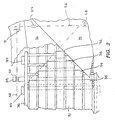
- the packaging machine has a tube-forming device 1, a transport device 2 with which objects 4 to be packaged are transported through the tube-forming device 1 into a tube 6 formed from film 5, and a discharge device 3 which holds the tube 6 emerging from the tube-forming device 1 and the therein arranged objects 4 transported away from the tube forming device 1 (FIG. 1).
- the tube shaping device 1 has an upper, first shaping shoulder 7 and a lower, second shaping shoulder 8 (FIG. 4), via which the film 5, which is removed from a supply roll 9 via a compensating roll 10, is successively guided to act as a hose 6 emerge from the tube forming device 1.
- the tube 6 essentially has a rectangular cross-section, the edges 11 of the film 5 overlapping at the bottom of the tube 6.
- the two shaped shoulders 7 and 8 essentially span two planes which are inclined to one another and intersect approximately in the transport plane defined by the transport device 2.
- the lower, second form shoulder 8 lies essentially in the conveying plane of the transport device 2, while the upper, first form shoulder 7 increases in the conveying direction 13 in such a way that the film 5, which over the upper form shoulder 7 is pulled, as shown in FIG. 4 from top right to bottom left.
- the shaping shoulders 7 and 8 have several pairs of shaping edges, over which the film 5 is guided and bent to be formed into the tube 6.
- the upper mold shoulder 7 has on its outer sides a first pair of mold edges 12, over which the outer edge regions of the film 5 are first guided near the edges 11 thereof before they reach the lower mold shoulder 8.
- the first mold edges 12 lie in a common plane, namely in the plane of the mold shoulder 7 and converge in the direction of the film 5 drawn over the first mold shoulder 7.
- the extensions of the mold edges 12 intersect at a convergence angle u (FIG. 5). As shown in Fig.
- the first mold shoulder 7 has two guide plates 14, each of which has one of the mold edges 12 and is movable, as will be described in more detail later, about the guidance and tension of the film 5 and the geometry of the emerging To be able to adjust the film tube 6.
- the baffles 14 are metal sheets.
- the lower, second shaped shoulder 8 also has two guide plates 15 and 16, which, however, do not lie in one plane like the guide plates 14, but are arranged in two parallel planes and overlap one another, with a narrower one between the two guide plates 15 and 16 according to FIG 1 is a horizontal gap through which the film 5 can be guided, as will be explained below.
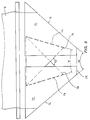
- the two guide plates 15 and 16 are substantially triangular and together have a second pair of mold edges 17, which are arranged on the outer sides of the mold shoulder 8, and a third pair of mold edges 18, which overlap one another and define a V-shaped opening at the front of the shape shoulder 8.
- the second mold edges 17 diverge in the direction of the hose 6 emerging from the hose molding device 1. Extensions of the second mold edges 17 intersect at a convergence angle v.
- the third shaped edges 18 converge in the direction of the emerging hose 6 and limit an angle w in the projection onto the conveying plane of the transport device 2.
- the arrangement of the mold edges to one another is such that the path across the various mold edges 12, 17, 18 and 19 along different lines, which are each parallel to the edges 11 of the film 5, measured from an entry of the film 5 into the tube forming device 1 on an entry edge 20 up to the exit of the film 5 on a vertical cross section of the tube 6 on the rear edges 21 of the lower shape shoulder 8 is of different lengths.
- the above-described path is shorter in regions near the edges 11 of the film 5 than in regions towards the longitudinal center axis of the film 5. As will be described in more detail later, this leads to the edges 11 running loosely and untensioned over the mold edges and, particularly in the region between the first mold edges 12 and the second mold edges 17, forming a belly (FIG. 4).
- the first molding edge 12 and the second molding edge 17 each overlapped by the film 5, that is, according to FIG. 5, a right one of the first and second molding edges and a left one of the first and second molding edges are not in arranged on a common level, but are skewed towards each other.
- the film 5 is thereby entangled in the area between the first mold edges 12 and the second mold edges 17.
- a multiplicity of angle combinations of the angles u, v and w are possible in order to achieve, on the one hand, the absence of tension in the edges 11 and, on the other hand, the entanglement of the film 5 in the region between two associated shape edges 12 and 17 .
- angles u, v and w can be, for example, 70, 20 and 90 °. If the angle u lying in the plane of the first shape shoulder 7 is projected into the plane of the angle v lying in the conveying plane, the projection of the angle u is always greater than the angle v.
- the molding edges 12, 17 and 18 are movable around and along different axes.
- the first shape shoulder 7 is displaceable along an axis a parallel to a connecting straight line of the front edge 19 of the first shape shoulder 7 and a front edge 210 of the second shape shoulder 8 (FIG. 6).
- a carrier 22, which is connected to the two guide plates 14 of the first shaped shoulder 7, is displaceably mounted on a stand 23 along the axis a and engages via an arm 24 with a spindle 25 for height adjustment of the first shaped shoulder 7. This eliminates the need for a handwheel that moves with the form shoulder.
- the spindle 25 can be driven by hand, preferably by means of a servomotor 50.
- the carrier 22 and the stand 23 are designed in two parts and each connected to one of the guide plates 14, around the guide plates 14 along an axis b transverse to the conveying direction of the transport device 2 and thereby to be able to set a width of the running hose 6.
- the adjustment of the guide plates 14 of the upper shape shoulder 7 is preferably carried out synchronously with a corresponding width adjustment of the guide plates 15 and 16 of the lower shape shoulder 8 likewise along a direction b.
- the two stands 23 can each be firmly connected to one of the guide plates 15 or 16 or they can be coupled to the two guide plates 15 and 16 on a common adjusting spindle 26. As shown in Fig.
- the two guide plates 15 and 16 are each engaged by means of a spindle nut 27 and 28 with different sections of the adjusting spindle 26, so that when the spindle 26 is actuated, the width of the V defined by the third form edges 18 -shaped opening of the lower shape shoulder 8 is set.
- the spindle drive shown other drive or. Adjustment devices can be used, but the spindle drive shown has a high precision with a simple construction.
- the spindle 26 can be driven by hand, preferably by means of a suitable servomotor 51.
- the track width of the tube shaping device 1 and thus the width of the tube 6 running off can be easily adjusted with the geometric relationships of the shape edges remaining the same.
- the guide plates 14 of the upper shape shoulder 7 can each be pivoted about an axis c which is perpendicular to the plane defined by the guide plates 14. As shown in FIGS. 4 and 6, the axes c each lie at a lower outer end of the guide plates 14.
- the position of the connection points of the first mold edge 12 and the fourth mold edge 19 is the same for different pivoting positions Baffles 14 such that the imaginary connection between the fourth pair of mold edges 19 and the tips, ie the connection points of the second and third mold edges, remains unchanged.
- the angle of convergence u is changed by pivoting the guide plates 14.
- the adjustment range is such that the convergence angle u or its projection into the plane of the angle v is always larger than the angle v.
- the film 5 is entangled in the region between the first mold edges 12 and the second mold edges 17.
- the guide plates 14 are each pivotably mounted on a plate-shaped base support 29.
- these can be coupled to one another, for example, via a spindle, similar to the two guide plates 15 and 16.
- a servomotor not shown, can also be provided for this.
- the fourth shaped edges 19 are formed by cylindrical rollers 30 which are rotatably mounted on the base support 29.
- the rollers 30 reduce the stress on the film 5 due to the relatively acute-angled deflection at the mold edge 4 and reduce the friction of the film 5 at this mold edge.
- the tension of the film 15 can be set in the regions of the edges 11 and the bulge of the film between the first mold edges 12 and the second mold edges 17.
- the transport device 2 In order to transport the objects 4 into the hose 6 spanned by the two form shoulders 7 and 8, the transport device 2, as shown in FIG. 1, has a plurality of narrow, parallel conveyor belts 31 which place the objects 4 on the lower form shoulder 8 or to slide the film 5 drawn over the lower shape shoulder 8.
- the conveyor belts 31 are guided around rollers 32, 33, 34 and 35 which are offset in a stepped manner such that the ends of the individual conveyor belts 31 are stepped in a V-shape and the V-shaped one delimited by the third shaped edges 18 Opening of the lower shape shoulder 7 are adjusted.
- the conveying path of the transport device 2 extends directly to the lower shape shoulder 8, which lies in the same plane with the conveying plane of the transport direction 2.
- the complementarily graded downstream conveying end of the transport device 2 can be pushed back and forth in such a way that the Conveyor path of the transport device 2 is adjustable in length.
- rollers 32, 33, 34 and 35 which define the downstream end, are mounted on a common carriage 36, which is mounted on a frame of the packaging machine, not shown, by means of sliding or roller bearings 37. If the width of the lower mold shoulder 8 is reduced, ie the guide plates 14 and 15 are pushed together or pushed further one above the other, the slide 36 is pushed back against the conveying direction of the transport device 2, so that the downstream end of the transport device does not collide with the third mold edges 18.
- the lower shape shoulder 8 is widened, ie when the two guide plates are pushed apart 15 and 16 transversely to the conveying direction, the downstream end is pushed forward in the conveying direction in order not to allow a gap to arise between the transport device 2 and the lower mold shoulder 8.
- the carriage 36 is preferably displaceable synchronously with the width adjustment of the lower shape shoulder 8.
- a carriage spindle 38 with which the carriage engages via an arm 39 and a spindle nut 40, is coupled by means of a bevel gear pair 41 to the adjusting spindle 26, with which the position of the guide plates 14 and the guide plates 15 and 16 is adjusted transversely to the conveying direction .
- the synchronous connection of the slide 36 with the shaped plates 15 and 16 can also be carried out individually by means of appropriately controlled servomotors, but the coupling of two spindle drives shown has a high degree of precision with a simple construction.
- the adjustment spindle 26 and the slide spindle 38 can be driven together by hand or with a suitable servomotor.
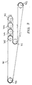
- the individual conveyor belts 31 are guided such that the distances traveled by the endlessly rotating conveyor belts 31 are the same for different settings of the downstream end of the upper run of the transport device 2.
- the individual conveyor belts 31 are first guided individually or in pairs around the displaceably mounted deflection rollers 32, 33, 34 and 35 and then together around a common deflection roller 41, which is also rotatably mounted on the displaceable carriage 36 and together with the deflection rollers 32, 33, 34 and 35 is displaceable in a direction parallel to the conveying direction.
- the conveyor belts 31 are thus each S-shaped around one of the deflection rollers 32, 33, 34 and 35 and the deflection roller 41.
- the deflection rollers 32 to 35 and 41 mounted on the slide 36 can be rotated between two fixed ones mounted deflection rollers 42 and 43, around which each of the conveyor belts 31 is guided.
- the section of the conveyor belts 31 between the deflection roller 43 and the deflection rollers 32 to 35 and the section of the conveyor belts 31 between the deflection roller 41 and the deflection roller 42 run in mutually parallel planes.
- the displaceable deflection unit with the deflection rollers 32 to 35 and 41 can be moved back and forth parallel to these planes in the conveying direction in order to adjust the position of the downstream conveying end of the transport device 2, the distance covered by the conveyor belts 31 being constant.
- the conveyor belts 31 can therefore be subjected to a predetermined and constant tension.
- a removal device 3 is provided for the removal of the objects 4 on the hose exit side of the hose shaping device 1.
- the discharge device 3 has a suction conveyor belt 45 perforated with air suction holes 44, which rotates endlessly and whose upper side lies in the plane of the second, lower shape shoulder 8.
- the upstream end of the conveyor 3 connects flush to a rear edge of the second, lower mold shoulder 8 and takes over the objects 4 pushed into the hose and the film hose 6 itself downstream of the hose shaping device 1.
- the area of the hose shaping device 1 itself ie in the area of the lower shaping shoulder 8, so no conveyor is provided.
- the objects 4 are transported in this area indirectly through the film 5, which is pulled over the guide plates 15 and 16 of the second, lower mold shoulder 8.
- the suction conveyor 3 also acts as a pulling device for the film 5 and can pull the film 5 through the tube forming device 1 even in the absence of objects 4 to be packaged. In particular, the threading of the film 5 into the tube forming device 1 is made easier as a result.
- the packaging machine shown also has a control device and a storage device, which are not shown in the figures.
- corresponding object names such as height, width, length and other parameters that influence the setting of the tube shaping device, such as color of the object or type of film, necessary melting temperature, etc.
- the control device is connected to the servomotors in order to control them as a function of the stored object parameters.
- the object to be packaged is selected via an input unit (also not shown), after which the parameters stored under the corresponding designation are read from the data memory by the control device.
- the control device uses this to calculate the target position for the actuators and controls them with corresponding signals.
- the calculated values are transferred to the engine control system via a bus system.
- the servomotors move to the desired position and report that the position value has been reached to the controller via the bus system. Accordingly, the tube shaping device is set completely automatically only by entering the object to be packaged.
- the film 5 is threaded into the tube forming device 1.
- the film 5 is removed from the supply roll by hand and guided over the guide plates 14 of the upper shape shoulder 7.
- the edge regions of the film 5 are over the first mold edges 12 of the first, upper mold shoulder 7 drawn and one after the other around the second and third mold edges of the guide plates 15 and 16.
- the section of the film 5 guided under the guide plate 15 and the edge of the film 5 folded over on the upper side of the guide plate 16 are pulled through the gap between the two guide plates 15 and 16.
- the film 5 is drawn through the tube forming device 1 to such an extent that a sufficient section comes to rest on the discharge conveyor 3.
- the width and height of the running hose 6 required for the respective objects 4 is set by actuating the adjusting spindle 26 and the height adjusting spindle 46. This can be done before or after threading the film 5 and is effected by the control device and the servomotors, which form a motorized adjusting device, after a corresponding input of the object.
- the film 5 is pulled through the tube forming device 1.
- the orientation of the first mold edges 12 can be adjusted by pivoting the guide plates 14.
- pivoting the guide plates 14 outwards in the direction of the arrows f the distance to be covered by the film in the region of the edges 11 is extended, the belly of the film 5 in the region between the first mold edges 12 and the second mold edges 17 is reduced and, if appropriate, the tension of the Foil 5 increased in the edge areas.
- Pushing the guide surface 14 against the arrows f reduces the tension in the edge regions 11 and increases the size of the belly which the film 5 throws in the region between the first and second mold edges 12 and 17.
- This angle setting can also be effected by the control device, readjustment possibly being carried out manually or by manually entering corrected setpoints.
- the objects 4 are transported from left to right on the transport device 2 and pushed into the film tunnel spanned by the shaped shoulders 7 and 8. In the area of the lower shape shoulder 8, the objects 4 are transported through the film 5 drawn over the lower shape shoulder 8. Downstream of the hose shaping device 1, the objects are transported away by the removal conveyor 3 and, if necessary, fed to a welding device.
Landscapes
- Engineering & Computer Science (AREA)
- Mechanical Engineering (AREA)
- Containers And Plastic Fillers For Packaging (AREA)
Priority Applications (1)
| Application Number | Priority Date | Filing Date | Title |
|---|---|---|---|
| EP99108893A EP0941927A3 (fr) | 1996-05-09 | 1997-04-23 | Machine d'emballage |
Applications Claiming Priority (2)
| Application Number | Priority Date | Filing Date | Title |
|---|---|---|---|
| DE19618559 | 1996-05-09 | ||
| DE19618559A DE19618559A1 (de) | 1996-05-09 | 1996-05-09 | Verpackungsmaschine |
Related Child Applications (1)
| Application Number | Title | Priority Date | Filing Date |
|---|---|---|---|
| EP99108893A Division EP0941927A3 (fr) | 1996-05-09 | 1997-04-23 | Machine d'emballage |
Publications (3)
| Publication Number | Publication Date |
|---|---|
| EP0806346A2 true EP0806346A2 (fr) | 1997-11-12 |
| EP0806346A3 EP0806346A3 (fr) | 1998-09-09 |
| EP0806346B1 EP0806346B1 (fr) | 1999-08-18 |
Family
ID=7793748
Family Applications (2)
| Application Number | Title | Priority Date | Filing Date |
|---|---|---|---|
| EP99108893A Withdrawn EP0941927A3 (fr) | 1996-05-09 | 1997-04-23 | Machine d'emballage |
| EP97106684A Expired - Lifetime EP0806346B1 (fr) | 1996-05-09 | 1997-04-23 | Machine d'emballage équipée d'un système pour former un tube |
Family Applications Before (1)
| Application Number | Title | Priority Date | Filing Date |
|---|---|---|---|
| EP99108893A Withdrawn EP0941927A3 (fr) | 1996-05-09 | 1997-04-23 | Machine d'emballage |
Country Status (4)
| Country | Link |
|---|---|
| US (1) | US5799470A (fr) |
| EP (2) | EP0941927A3 (fr) |
| DE (2) | DE19618559A1 (fr) |
| ES (1) | ES2138412T3 (fr) |
Cited By (1)
| Publication number | Priority date | Publication date | Assignee | Title |
|---|---|---|---|---|
| DE102024110670A1 (de) * | 2024-04-16 | 2025-10-16 | Jens Kallfass | Verfahren und Vorrichtung zum Verpacken von Gegenständen und Verwendung einer Folie für dieses Verfahren |
Families Citing this family (9)
| Publication number | Priority date | Publication date | Assignee | Title |
|---|---|---|---|---|
| CA2254105C (fr) * | 1997-03-11 | 2008-06-03 | Ranpak Corp. | Convertisseur pour matelassage et procede correspondant |
| DE19953220A1 (de) * | 1999-11-05 | 2001-05-10 | Barsch Horizontale Verpackungs | Horizontale Schlauchbeutelverpackungsmaschine |
| WO2002036431A2 (fr) * | 2000-10-30 | 2002-05-10 | Stork Fabricators, Inc. | Machine d'emballage modulaire sous film rétractable |
| DE10251072A1 (de) * | 2002-11-02 | 2004-05-13 | Rovema Verpackungsmaschinen Gmbh | Formschulter zur Umformung einer Folienbahn |
| US10926507B2 (en) * | 2014-06-27 | 2021-02-23 | Pregis Intellipack Llc | Protective packaging machines demonstrative content |
| KR102410333B1 (ko) | 2015-07-07 | 2022-06-20 | 오씨아이 주식회사 | 포장장치 |
| DE102019132878A1 (de) * | 2019-12-03 | 2021-06-10 | Syntegon Packaging Systems Ag | Horizontalformvorrichtung |
| IT202000014857A1 (it) * | 2020-06-22 | 2021-12-22 | Ilapak Int S A | Gruppo piegatore per la piegatura di un materiale in film a formare un involucro tubolare. |
| EP4166462A1 (fr) * | 2021-10-15 | 2023-04-19 | MULTIVAC Sepp Haggenmüller SE & Co. KG | Machine de scellement et procédé de réglage des caractéristiques d'une machine de scellement |
Family Cites Families (21)
| Publication number | Priority date | Publication date | Assignee | Title |
|---|---|---|---|---|
| DE1164918B (de) * | 1961-09-16 | 1964-03-05 | Hoefliger & Karg | Formstueck zum Herstellen eines Verpackungsschlauchs mit rechteckigem Querschnitt aus einem Folienband |
| CH397517A (de) * | 1962-01-31 | 1965-08-15 | Hamac Hansella Aktiengesellsch | Vorrichtung zum Umformen eines Bandes aus Papier oder Kunststoff zu einem Schlauch |
| US3636826A (en) * | 1969-10-24 | 1972-01-25 | Burlie R Bowen | Folding shoe for use in a packaging machine |
| DE2657790A1 (de) * | 1976-12-21 | 1978-06-22 | Rovema Gmbh | Schlauchbeutelmaschine |
| DK150740C (da) * | 1977-09-01 | 1988-02-08 | Gram Brdr As | Fremgangsmaade til brug ved overfoering af genstande fra en kontinuert bevaeget tilfoerselstransportoer og til en modtagertransportoer samt transportanlaeg til brug ved udoevelse af fremgangsmaaden |
| DE3114102A1 (de) * | 1980-04-09 | 1982-02-25 | DRG (UK) Ltd., Bristol | Verfahren und vorrichtung zum zufuehren von boegen au papier, pappe o.dgl. |
| US4494362A (en) * | 1981-03-24 | 1985-01-22 | Metromail, Inc. | Package forming web folder |
| DE3152023A1 (de) * | 1981-06-27 | 1983-01-13 | Beck & Co Packautomaten, 7440 Nürtingen | "vorrichtung zur umlenkung einer fortlaufenden folienbahn in einer verpackungsmaschine" |
| US4537016A (en) * | 1982-12-30 | 1985-08-27 | Shanklin Corporation | Horizontal form, fill, seal machines |
| US4679379A (en) * | 1983-09-13 | 1987-07-14 | Cassoli S.R.L. Macchine Automatiche Confezionatrici | Automatic bundling machine |
| GB2165202B (en) * | 1984-10-08 | 1988-05-11 | Grace W R & Co | A horizontal form-fill-seal machine |
| JPS62135107A (ja) * | 1985-12-05 | 1987-06-18 | 株式会社ハナガタ | 物品の包装装置 |
| IT1208412B (it) * | 1987-04-28 | 1989-06-12 | Cavanna Spa | Gruppo formatore regolabile per macchine confezionatrici di involucri del tipo flow pack e simili e relativo procedimento |
| DE3837441A1 (de) * | 1988-11-04 | 1990-05-17 | 4 P Nicolaus Kempten Gmbh | Einrichtung zum ueberpruefen und sortieren von faltschachteln od. dgl. |
| DE4021934A1 (de) * | 1990-07-10 | 1992-01-16 | Haussmann Packmaschinen Gmbh | Verstellbare schlauchbeutelverpackungsmaschine |
| DE4021935A1 (de) * | 1990-07-10 | 1992-01-16 | Haussmann Packmaschinen Gmbh | Schnelle schlauchbeutelverpackungsmaschine |
| US5237800A (en) * | 1991-03-29 | 1993-08-24 | Omori Machinery Co., Ltd. | Shrink-wrapping method and apparatus |
| US5165221A (en) * | 1991-07-02 | 1992-11-24 | Great Lakes Corporation | Adjustable film forming apparatus |
| US5255495A (en) * | 1992-10-30 | 1993-10-26 | Hayssen Manufacturing Company | Adjustable girth former |
| US5408806A (en) * | 1993-08-03 | 1995-04-25 | Industrial Technology Research Institute | Horizontal type of packing machine with an adjustable pouch former |
| JP2733444B2 (ja) * | 1994-05-27 | 1998-03-30 | 株式会社ハナガタ | フィルム等の帯状包装材料による包装機 |
-
1996
- 1996-05-09 DE DE19618559A patent/DE19618559A1/de not_active Withdrawn
-
1997
- 1997-04-23 EP EP99108893A patent/EP0941927A3/fr not_active Withdrawn
- 1997-04-23 EP EP97106684A patent/EP0806346B1/fr not_active Expired - Lifetime
- 1997-04-23 ES ES97106684T patent/ES2138412T3/es not_active Expired - Lifetime
- 1997-04-23 DE DE59700342T patent/DE59700342D1/de not_active Expired - Fee Related
- 1997-05-07 US US08/852,526 patent/US5799470A/en not_active Expired - Fee Related
Cited By (2)
| Publication number | Priority date | Publication date | Assignee | Title |
|---|---|---|---|---|
| DE102024110670A1 (de) * | 2024-04-16 | 2025-10-16 | Jens Kallfass | Verfahren und Vorrichtung zum Verpacken von Gegenständen und Verwendung einer Folie für dieses Verfahren |
| EP4635863A1 (fr) | 2024-04-16 | 2025-10-22 | Jens Kallfass | Procédé et dispositif pour emballer des objets et utilisation d'une feuille pour ce procédé |
Also Published As
| Publication number | Publication date |
|---|---|
| DE59700342D1 (de) | 1999-09-23 |
| EP0806346A3 (fr) | 1998-09-09 |
| EP0806346B1 (fr) | 1999-08-18 |
| EP0941927A3 (fr) | 2000-04-12 |
| DE19618559A1 (de) | 1997-11-13 |
| EP0941927A2 (fr) | 1999-09-15 |
| US5799470A (en) | 1998-09-01 |
| ES2138412T3 (es) | 2000-01-01 |
Similar Documents
| Publication | Publication Date | Title |
|---|---|---|
| DE1704146C3 (de) | Verfahren und Einrichtung zum kontinuierlichen Herstellen von Beuteln Ausscheidung aus 1248911 | |
| DE3525040C2 (de) | Einrichtung zur Umlenkung der Förderrichtung von Papierblättern | |
| DE19515719C2 (de) | Vorrichtung zum Verpacken von Gegenständen in Schlauchbeutel | |
| EP0806346B1 (fr) | Machine d'emballage équipée d'un système pour former un tube | |
| DE2746670C2 (de) | Vorrichtung zum Stapeln von Beuteln | |
| DE4338232A1 (de) | Vorrichtung zur Verarbeitung eines zu einem Stapel aufgeschichteten Teigbandes | |
| DE1953969A1 (de) | Verfahren und Vorrichtung zum Verpacken von Gegenstaenden | |
| EP0697989B1 (fr) | Dispositif permettant de transferer et d'empiler des feuilles | |
| CH689449A5 (de) | Verfahren zum Beschneiden von flachen Druckprodukten laengs einer vorgegebenen Schnittlinie. | |
| DE2236524A1 (de) | Vorrichtung zum herstellen von beuteln oder dergleichen verpackungen aus thermoplastischer kunststoffolie und deren stapelung | |
| DE3113399A1 (de) | Ausrichtvorrichtung fuer die kanten eines aus falzprodukten bestehenden schuppenstroms | |
| DE29917881U1 (de) | Umreifungsmaschine zum Umreifen eines Gutstapels | |
| DE4413008A1 (de) | Faltvorrichtung für Blattlagen | |
| DE19515718A1 (de) | Vorrichtung zum Verpacken von Gegenständen in einen Schlauchbeutel | |
| DE2537882C2 (de) | Vorrichtung zum Verpacken von Gegenständen in Folie | |
| DE4314756C2 (de) | Vorrichtung zum Schuppen und Ablegen von Bogen auf einen Stapel | |
| EP0860266B1 (fr) | Dispositif de soudage | |
| DE3744107C2 (fr) | ||
| EP3369663B1 (fr) | Dispositif de bottelage pour pièces à usiner oblongues ainsi que procédé de bottelage de pièces à usiner oblongues | |
| EP1050463B1 (fr) | Machine de liage pour lier une pile d'objets | |
| EP1270261B1 (fr) | Méthode pour l'insertion, d'au moins, un signet dans un corps d'ouvrage ainsi que dispositif pour mettre en oeuvre le procédé | |
| DE19804226C1 (de) | Verfahren und Vorrichtung zum automatischen Nachjustieren einer Folienrolle | |
| DE9014215U1 (de) | Verpackungsmaschine, insbesondere Banderoliermaschine | |
| DE19625818A1 (de) | Vorrichtung und Verfahren zur Bearbeitung von Lagenmaterial | |
| DE102021116617A1 (de) | Mehrspuriger Interleaver-Slicer sowie Verfahren für dessen Betrieb |
Legal Events
| Date | Code | Title | Description |
|---|---|---|---|
| PUAI | Public reference made under article 153(3) epc to a published international application that has entered the european phase |
Free format text: ORIGINAL CODE: 0009012 |
|
| AK | Designated contracting states |
Kind code of ref document: A2 Designated state(s): CH DE ES FR GB IT LI NL SE |
|
| PUAL | Search report despatched |
Free format text: ORIGINAL CODE: 0009013 |
|
| AK | Designated contracting states |
Kind code of ref document: A3 Designated state(s): CH DE ES FR GB IT LI NL SE |
|
| 17P | Request for examination filed |
Effective date: 19980924 |
|
| 17Q | First examination report despatched |
Effective date: 19990212 |
|
| GRAG | Despatch of communication of intention to grant |
Free format text: ORIGINAL CODE: EPIDOS AGRA |
|
| GRAG | Despatch of communication of intention to grant |
Free format text: ORIGINAL CODE: EPIDOS AGRA |
|
| GRAH | Despatch of communication of intention to grant a patent |
Free format text: ORIGINAL CODE: EPIDOS IGRA |
|
| GRAH | Despatch of communication of intention to grant a patent |
Free format text: ORIGINAL CODE: EPIDOS IGRA |
|
| GRAA | (expected) grant |
Free format text: ORIGINAL CODE: 0009210 |
|
| AK | Designated contracting states |
Kind code of ref document: B1 Designated state(s): CH DE ES FR GB IT LI NL SE |
|
| REG | Reference to a national code |
Ref country code: CH Ref legal event code: NV Representative=s name: TROESCH SCHEIDEGGER WERNER AG Ref country code: CH Ref legal event code: EP |
|
| REF | Corresponds to: |
Ref document number: 59700342 Country of ref document: DE Date of ref document: 19990923 |
|
| ITF | It: translation for a ep patent filed | ||
| GBT | Gb: translation of ep patent filed (gb section 77(6)(a)/1977) |
Effective date: 19991109 |
|
| ET | Fr: translation filed | ||
| REG | Reference to a national code |
Ref country code: ES Ref legal event code: FG2A Ref document number: 2138412 Country of ref document: ES Kind code of ref document: T3 |
|
| PGFP | Annual fee paid to national office [announced via postgrant information from national office to epo] |
Ref country code: FR Payment date: 20000417 Year of fee payment: 4 |
|
| PGFP | Annual fee paid to national office [announced via postgrant information from national office to epo] |
Ref country code: SE Payment date: 20000425 Year of fee payment: 4 |
|
| PGFP | Annual fee paid to national office [announced via postgrant information from national office to epo] |
Ref country code: ES Payment date: 20000426 Year of fee payment: 4 |
|
| PLBE | No opposition filed within time limit |
Free format text: ORIGINAL CODE: 0009261 |
|
| STAA | Information on the status of an ep patent application or granted ep patent |
Free format text: STATUS: NO OPPOSITION FILED WITHIN TIME LIMIT |
|
| 26N | No opposition filed | ||
| PG25 | Lapsed in a contracting state [announced via postgrant information from national office to epo] |
Ref country code: GB Free format text: LAPSE BECAUSE OF NON-PAYMENT OF DUE FEES Effective date: 20010423 |
|
| PG25 | Lapsed in a contracting state [announced via postgrant information from national office to epo] |
Ref country code: SE Free format text: LAPSE BECAUSE OF NON-PAYMENT OF DUE FEES Effective date: 20010424 Ref country code: ES Free format text: LAPSE BECAUSE OF NON-PAYMENT OF DUE FEES Effective date: 20010424 |
|
| PG25 | Lapsed in a contracting state [announced via postgrant information from national office to epo] |
Ref country code: FR Free format text: THE PATENT HAS BEEN ANNULLED BY A DECISION OF A NATIONAL AUTHORITY Effective date: 20010430 |
|
| PG25 | Lapsed in a contracting state [announced via postgrant information from national office to epo] |
Ref country code: LI Free format text: LAPSE BECAUSE OF NON-PAYMENT OF DUE FEES Effective date: 20010522 Ref country code: CH Free format text: LAPSE BECAUSE OF NON-PAYMENT OF DUE FEES Effective date: 20010522 |
|
| PGFP | Annual fee paid to national office [announced via postgrant information from national office to epo] |
Ref country code: DE Payment date: 20010615 Year of fee payment: 5 |
|
| PG25 | Lapsed in a contracting state [announced via postgrant information from national office to epo] |
Ref country code: NL Free format text: LAPSE BECAUSE OF NON-PAYMENT OF DUE FEES Effective date: 20011101 |
|
| EUG | Se: european patent has lapsed |
Ref document number: 97106684.0 |
|
| GBPC | Gb: european patent ceased through non-payment of renewal fee |
Effective date: 20010423 |
|
| REG | Reference to a national code |
Ref country code: CH Ref legal event code: PL |
|
| NLV4 | Nl: lapsed or anulled due to non-payment of the annual fee |
Effective date: 20011101 |
|
| REG | Reference to a national code |
Ref country code: FR Ref legal event code: ST |
|
| PG25 | Lapsed in a contracting state [announced via postgrant information from national office to epo] |
Ref country code: DE Free format text: LAPSE BECAUSE OF NON-PAYMENT OF DUE FEES Effective date: 20021101 |
|
| REG | Reference to a national code |
Ref country code: ES Ref legal event code: FD2A Effective date: 20030303 |
|
| PG25 | Lapsed in a contracting state [announced via postgrant information from national office to epo] |
Ref country code: IT Free format text: LAPSE BECAUSE OF NON-PAYMENT OF DUE FEES Effective date: 20050423 |