EP0806367A1 - A container and end closure adapted for evacuating and back-flushing of gases during closing - Google Patents
A container and end closure adapted for evacuating and back-flushing of gases during closing Download PDFInfo
- Publication number
- EP0806367A1 EP0806367A1 EP97302835A EP97302835A EP0806367A1 EP 0806367 A1 EP0806367 A1 EP 0806367A1 EP 97302835 A EP97302835 A EP 97302835A EP 97302835 A EP97302835 A EP 97302835A EP 0806367 A1 EP0806367 A1 EP 0806367A1
- Authority
- EP
- European Patent Office
- Prior art keywords
- container
- crown
- chuck wall
- projections
- panel
- Prior art date
- Legal status (The legal status is an assumption and is not a legal conclusion. Google has not performed a legal analysis and makes no representation as to the accuracy of the status listed.)
- Granted
Links
- 239000007789 gas Substances 0.000 title claims abstract description 34
- 238000011010 flushing procedure Methods 0.000 title claims abstract description 10
- 238000004826 seaming Methods 0.000 claims abstract description 64
- 238000007789 sealing Methods 0.000 claims abstract description 20
- 150000001875 compounds Chemical class 0.000 claims abstract description 9
- 239000002184 metal Substances 0.000 claims description 18
- 239000004033 plastic Substances 0.000 claims description 8
- 239000000463 material Substances 0.000 claims description 5
- 230000000063 preceeding effect Effects 0.000 claims 2
- 239000002131 composite material Substances 0.000 description 16
- 229940126639 Compound 33 Drugs 0.000 description 6
- PNUZDKCDAWUEGK-CYZMBNFOSA-N Sitafloxacin Chemical compound C([C@H]1N)N(C=2C(=C3C(C(C(C(O)=O)=CN3[C@H]3[C@H](C3)F)=O)=CC=2F)Cl)CC11CC1 PNUZDKCDAWUEGK-CYZMBNFOSA-N 0.000 description 6
- 238000004519 manufacturing process Methods 0.000 description 5
- IJGRMHOSHXDMSA-UHFFFAOYSA-N Atomic nitrogen Chemical compound N#N IJGRMHOSHXDMSA-UHFFFAOYSA-N 0.000 description 2
- SMNRFWMNPDABKZ-WVALLCKVSA-N [[(2R,3S,4R,5S)-5-(2,6-dioxo-3H-pyridin-3-yl)-3,4-dihydroxyoxolan-2-yl]methoxy-hydroxyphosphoryl] [[[(2R,3S,4S,5R,6R)-4-fluoro-3,5-dihydroxy-6-(hydroxymethyl)oxan-2-yl]oxy-hydroxyphosphoryl]oxy-hydroxyphosphoryl] hydrogen phosphate Chemical compound OC[C@H]1O[C@H](OP(O)(=O)OP(O)(=O)OP(O)(=O)OP(O)(=O)OC[C@H]2O[C@H]([C@H](O)[C@@H]2O)C2C=CC(=O)NC2=O)[C@H](O)[C@@H](F)[C@@H]1O SMNRFWMNPDABKZ-WVALLCKVSA-N 0.000 description 2
- 239000011324 bead Substances 0.000 description 2
- 239000002657 fibrous material Substances 0.000 description 2
- 230000002028 premature Effects 0.000 description 2
- QVGXLLKOCUKJST-UHFFFAOYSA-N atomic oxygen Chemical compound [O] QVGXLLKOCUKJST-UHFFFAOYSA-N 0.000 description 1
- 235000013361 beverage Nutrition 0.000 description 1
- 239000011888 foil Substances 0.000 description 1
- 238000000034 method Methods 0.000 description 1
- 229910052757 nitrogen Inorganic materials 0.000 description 1
- 239000001301 oxygen Substances 0.000 description 1
- 229910052760 oxygen Inorganic materials 0.000 description 1
- 238000004806 packaging method and process Methods 0.000 description 1
- 229920003051 synthetic elastomer Polymers 0.000 description 1
- 239000005061 synthetic rubber Substances 0.000 description 1
- -1 synthetic rubbers Chemical class 0.000 description 1
Images


Classifications
-
- B—PERFORMING OPERATIONS; TRANSPORTING
- B65—CONVEYING; PACKING; STORING; HANDLING THIN OR FILAMENTARY MATERIAL
- B65D—CONTAINERS FOR STORAGE OR TRANSPORT OF ARTICLES OR MATERIALS, e.g. BAGS, BARRELS, BOTTLES, BOXES, CANS, CARTONS, CRATES, DRUMS, JARS, TANKS, HOPPERS, FORWARDING CONTAINERS; ACCESSORIES, CLOSURES, OR FITTINGS THEREFOR; PACKAGING ELEMENTS; PACKAGES
- B65D7/00—Containers having bodies formed by interconnecting or uniting two or more rigid, or substantially rigid, components made wholly or mainly of metal
- B65D7/02—Containers having bodies formed by interconnecting or uniting two or more rigid, or substantially rigid, components made wholly or mainly of metal characterised by shape
- B65D7/04—Containers having bodies formed by interconnecting or uniting two or more rigid, or substantially rigid, components made wholly or mainly of metal characterised by shape of curved cross-section, e.g. cans of circular or elliptical cross-section
-
- B—PERFORMING OPERATIONS; TRANSPORTING
- B65—CONVEYING; PACKING; STORING; HANDLING THIN OR FILAMENTARY MATERIAL
- B65D—CONTAINERS FOR STORAGE OR TRANSPORT OF ARTICLES OR MATERIALS, e.g. BAGS, BARRELS, BOTTLES, BOXES, CANS, CARTONS, CRATES, DRUMS, JARS, TANKS, HOPPERS, FORWARDING CONTAINERS; ACCESSORIES, CLOSURES, OR FITTINGS THEREFOR; PACKAGING ELEMENTS; PACKAGES
- B65D51/00—Closures not otherwise provided for
- B65D51/16—Closures not otherwise provided for with means for venting air or gas
- B65D51/1672—Closures not otherwise provided for with means for venting air or gas whereby venting occurs by manual actuation of the closure or other element
- B65D51/1688—Venting occurring during initial closing or opening of the container, by means of a passage for the escape of gas between the closure and the lip of the container mouth, e.g. interrupted threads
- B65D51/1694—Venting occurring during initial closing or opening of the container, by means of a passage for the escape of gas between the closure and the lip of the container mouth, e.g. interrupted threads the closure being for a box-like container
Definitions
- This invention relates to a container and end for closing and sealing the container with a double seaming operation and being adapted for permitting evacuating and back-flushing of gases out of and into the container while the end is in a seated and unseamed position on the container during the closing operation.
- an end which includes a central circular panel, a chuck wall surrounding an outer periphery of the central panel and extending radially outwardly and upwardly from the central panel and a crown seaming panel surrounding the chuck wall and extending radially outwardly from the chuck wall and having an outer curled end.
- the chuck wall and the crown seaming panel preferably have sealing compound on a portion of their inner surfaces and are the portions which are double-seamed with the flanged outer end portion of the container.
- Separate projections are formed in the chuck wall and in the crown seaming panel and extend inwardly and radially of the chuck wall and the crown seaming panel, respectively. These projections are spaced around the chuck wall and around the crown seaming panel and are adapted to engage the flanged upper end of the container being closed for forming gas channels between the respective projections and between the flanged upper end of the container and the chuck wall and the crown seaming panel of the end when the end is in a seated and unseamed position on the container during the double-seaming closing operation.
- the projections alternate in spacing between the chuck wall and the crown seaming panel around the end.
- the gas channel-forming projections in one of the chuck walls or crown seaming panel comprise pairs of closely spaced projections in which the pairs of projections are equally spaced around the end.
- the gas channel-forming projections in one, preferably the other, of the chuck wall and the crown seaming panel comprise single projections equally spaced around the end. It has also been found particularly preferable to position the pairs of projections in the chuck wall and to position the single projections in the crown seaming panel.
- While this invention is particularly adapted for use with a metal end double-seamed on and closing a composite container, it is also applicable for use with an end constructed of either metal or plastic and a container constructed of metal, plastic or composites.
- the generally cylindrical container 10 includes an outwardly-flanged upper end portion 11 for being double-seamed with the end 20 to close the container 10 in a manner to be described more fully below.
- the bottom 12 of the container 10 may be closed in any conventional manner or may include an end 20 of the type to be described more specifically below.
- the container 10 may be constructed of metal or plastic, but preferably is constructed of composites. Composites are well known in the container industry and may include multiple layers of various materials which may be spirally wound, convolutely wound or otherwise formed into a cylindrical container. These composite materials and their manufacture into a cylindrical container are well known by those with ordinary skill in the art and further explanation herein is not deemed necessary.
- the end 20 used for closing of the container 10 by a double-seaming operation includes a central circular panel 21 and a chuck wall 22 surrounding an outer periphery of the central panel 21 and extending radially outwardly and upwardly from the central panel 21 .
- the end 20 further includes a crown seaming panel 23 surrounding the chuck wall 22 and extending radially outwardly from the chuck wall and having an outer curled end 23A .
- Sealing compound 33, 34 (to be discussed in more detail below) is preferably positioned on an inside surface of a portion of the chuck wall 22 and a portion of the crown seaming panel 23 .
- the compound 33 , 34 does not extend past the center line CL of the crown seaming panel and does not extend down the chuck wall past the curl height CH of the outer curled end 23A , as shown in Fig. 1A.
- This sealing compound 33, 34 may comprise any suitable sealing compounds including synthetic rubbers, etc.
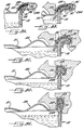
- the chuck wall 22 and crown seaming panel 23 with curled outer end 23A are utilized to be double-seamed with the flanged outer end portion 11 of the container 10 during the double-seaming operation, as shown schematically in Figs. 9A-9E wherein these components are deformed and bent in sequence to form the ultimate double-seam by conventional container closing apparatus (also schematically shown) in a manner well understood by those with ordinary skill in the art.
- Separate projections 31, 32 are formed in the chuck wall 22 and in the crown seaming panel 23 and extend inwardly and radially of the chuck wall 22 and crown seaming panel 23 , respectively, and are spaced around the chuck wall 22 and crown seaming panel 23 , as shown particularly in Fig. 2.
- Chuck wall projections 31 include compound 33 and crown seaming panel projections 32 include compound 34 on their respective inside surfaces.
- projections 31, 32 engage the flanged upper end 11 of the container 10 being closed for forming gas channels 35 between respective projections 31, 32 and the sealing compound 33, 34 and between the flanged upper end portion 11 of the container 10 and the chuck wall 22 and the crown seaming panel 23 of the end 20 when the end 20 is in a seated and unseamed position on the container 10 during closing, as shown in Figs. 3-8 and in Figs. 9A-9E.
- the size and shape, along with the number, of projections 31 , 32 and resulting gas channels 35 utilized on each end 20 and the placement thereof in the chuck wall 22 and crown seaming panel 23 may vary due to the diameter of the end 20 , the thickness of the material forming the end 20 , countersink depth or other constructional features.
- the channel forming projections 31, 32 in one of the chuck wall 22 or crown seaming panel 23 comprise pairs of closely spaced projections and in which said pairs of projections are equally spaced around the end.
- the channel forming projections 31, 32 in one of the chuck wall 22 or crown seaming panel 23 comprise single projections equally spaced around the end 20 . It has been found further desirable that the projections 31 in the chuck wall 22 comprise the pairs of closely spaced projections which are equally spaced around the end 21 and wherein the gas channel-forming projections 32 in the crown seaming panel 23 comprise the single projections equally spaced around the end 20 and wherein the pairs of projections 31 in the chuck wall 22 alternate in spacing with the single projections 32 in the crown seaming panel 23 , as shown in Fig. 2.
Landscapes
- Engineering & Computer Science (AREA)
- Mechanical Engineering (AREA)
- Rigid Containers With Two Or More Constituent Elements (AREA)
- Closures For Containers (AREA)
- Pressure Vessels And Lids Thereof (AREA)
- Seal Device For Vehicle (AREA)
- Gasket Seals (AREA)
Abstract
Description
- This invention relates to a container and end for closing and sealing the container with a double seaming operation and being adapted for permitting evacuating and back-flushing of gases out of and into the container while the end is in a seated and unseamed position on the container during the closing operation.
- Heretofore, it has been conventional practice in the packaging field to manufacture metallic containers or cans for storage of comestibles, beverages and other various products which include a cylindrical open-end container body fabricated from sheet metal and having a metal end closure which is double-seamed onto an outwardly flanged end portion of the container body at one or both ends and which includes a sealing compound between the metal end closure and the flanged end portion of the container body. Such closing operation of the end on the container utilizing double-seaming has been a favored form of assembling containers and end closures since it is readily adapted to production line manufacturing capabilities and at the same time providing a reliable hermetic seal capable of withstanding substantial pressure differentials which may exist, or be encountered, between the ambient atmosphere and the interior confines of the filled container during processing of the container's contents or during subsequent shipping and storing.
- During the closing operation of the end on the container, it is often desired to evacuate gases from the container with the contents therein and back-fill the container with other gases, i.e. evacuating oxygen and back-filling with nitrogen. In order to be able to carry out this evacuating and back-filling of gases, it is necessary when the end is positioned on the container that there be provided gas channels between the end and the flanged end portion of the container and that premature sealing between the end and the container by the sealing compound be avoided at the gas channels. Heretofore, this has been primarily accomplished by utilizing "stand-off beads" produced by forming a rounded dimple in the upper surface of the crown seaming panel, i.e. that portion of the end which is deformed during the double-seaming closing operation. This in turn forms an inwardly extending projection for engaging and maintaining the end in a slightly raised relationship on the flanged outer end portion of the container when the end is positioned on the container for closing and prior to completion of the double-seaming operation so that the evacuation and back-flushing of gases out of and into the container can be performed with devices on the conventional container closing apparatus and just prior to hermetic sealing of the container.
- Due in large part to manufacturing and shipping costs considerations and costs of materials, the container industry has been moving away from the use of metal containers and towards the use of plastic or preferably composite containers, i.e. container bodies fabricated from coated or uncoated fibrous material or composite multiple layers of fibrous material together with other compatible layers of materials such as plastic and/or foil liners, etc. The use of composite materials for the container have created additional problems or enhanced current problems with the evacuating and back-flushing of gases out of and into the container during the closing operation. For example, premature sealing of the flanged upper end of the composite container with the metal end through the sealing compound occurs due to the lack of stiffness in the composite container, as compared to a metal container, at the area in which the "stand-off beads" on the crown seaming panel of the metal end engage the flanged upper end portion of the composite container. Also, it has been found that the composite containers suffered from a condition described as "necking-in" which occurs when the inside diameter of the composite container is reduced due to the evacuating and back-flushing of gases and the closing of the metal end on the composite container with the double-seaming operation. This process can push the metal end into the flanged area of the container body plugging up the opening into the container. Metal container bodywalls are stronger and usually prevent this necking-in condition.
- Accordingly, it is an object of this invention to provide a generally cylindrical container and a generally circular end adapted for closing and sealing the container with sealing compound and a double-seaming operation and which is adapted for overcoming prior problems and permit superior evacuating and back-flushing of gases out of and into the container while the end is in a seated and unseamed position on the container during the closing operation.
- By this invention, it has been found that the above object may be accomplished by providing an end which includes a central circular panel, a chuck wall surrounding an outer periphery of the central panel and extending radially outwardly and upwardly from the central panel and a crown seaming panel surrounding the chuck wall and extending radially outwardly from the chuck wall and having an outer curled end. The chuck wall and the crown seaming panel preferably have sealing compound on a portion of their inner surfaces and are the portions which are double-seamed with the flanged outer end portion of the container.
- Separate projections are formed in the chuck wall and in the crown seaming panel and extend inwardly and radially of the chuck wall and the crown seaming panel, respectively. These projections are spaced around the chuck wall and around the crown seaming panel and are adapted to engage the flanged upper end of the container being closed for forming gas channels between the respective projections and between the flanged upper end of the container and the chuck wall and the crown seaming panel of the end when the end is in a seated and unseamed position on the container during the double-seaming closing operation.
- Preferably, the projections alternate in spacing between the chuck wall and the crown seaming panel around the end. It is also preferable that the gas channel-forming projections in one of the chuck walls or crown seaming panel comprise pairs of closely spaced projections in which the pairs of projections are equally spaced around the end. It is also preferable that the gas channel-forming projections in one, preferably the other, of the chuck wall and the crown seaming panel comprise single projections equally spaced around the end. It has also been found particularly preferable to position the pairs of projections in the chuck wall and to position the single projections in the crown seaming panel.
- While this invention is particularly adapted for use with a metal end double-seamed on and closing a composite container, it is also applicable for use with an end constructed of either metal or plastic and a container constructed of metal, plastic or composites.
- At least some of the objects and advantages of this invention have been set forth above, while other objects and advantages may appear in the detailed description of the preferred embodiment of the invention to follow, when taken in conjunction with the accompanying drawings in which:
- Fig. 1 is an exploded side elevational view, cut away, of a container and end closure (shown in section) constructed in accordance with this invention;
- Fig. 1A is an enlarged sectional view of a portion of the end closure as shown in Fig. 1 and taken within the circle indicated in Fig. 1;
- Fig. 2 is a top plan view, taken generally along the line 2-2 of Fig. 1, of the end closure;
- Fig. 3 is an enlarged partial top plan view of an area, as shown in the circle in Fig. 2, of the chuck wall of the end closure having a pair of projections therein for forming gas channels;
- Fig. 4 is an enlarged sectional view, taken generally along the line 4-4 of Fig. 3;
- Fig. 5 is a sectional view, taken generally along the line 5-5 of Fig. 4;
- Fig. 6 is an enlarged partial top plan view of an area, as shown in the circle in Fig. 2, of the crown seaming panel of the end closure having a single projection therein for forming gas channels;
- Fig. 7 is an enlarged sectional view, taken generally along the line 7-7 of Fig. 6;
- Fig. 8 is a section view, taken generally along the line 8-8 of Fig. 7; and
- Figs. 9A-E are sequential sectional views, like Figs. 4 and 7, illustrating the sequential steps involved in closing of the flanged end of a container with an end using a double-seaming operation and while evacuating and back-flushing of gases from and into the container during such closing operation.
- Referring now to the drawings, a generally
cylindrical container 10 and a generallycircular end 20 constructed in accordance with this invention are illustrated in exploded condition in Fig. 1 with thecontainer 10 being broken away to conserve space. The generallycylindrical container 10 includes an outwardly-flangedupper end portion 11 for being double-seamed with theend 20 to close thecontainer 10 in a manner to be described more fully below. Thebottom 12 of thecontainer 10 may be closed in any conventional manner or may include anend 20 of the type to be described more specifically below. Thecontainer 10 may be constructed of metal or plastic, but preferably is constructed of composites. Composites are well known in the container industry and may include multiple layers of various materials which may be spirally wound, convolutely wound or otherwise formed into a cylindrical container. These composite materials and their manufacture into a cylindrical container are well known by those with ordinary skill in the art and further explanation herein is not deemed necessary. - The
end 20 used for closing of thecontainer 10 by a double-seaming operation includes a centralcircular panel 21 and achuck wall 22 surrounding an outer periphery of thecentral panel 21 and extending radially outwardly and upwardly from thecentral panel 21. Theend 20 further includes acrown seaming panel 23 surrounding thechuck wall 22 and extending radially outwardly from the chuck wall and having an outer curledend 23A.Sealing compound 33, 34 (to be discussed in more detail below) is preferably positioned on an inside surface of a portion of thechuck wall 22 and a portion of thecrown seaming panel 23. Preferably, thecompound curled end 23A, as shown in Fig. 1A. This sealingcompound chuck wall 22 andcrown seaming panel 23 with curledouter end 23A are utilized to be double-seamed with the flangedouter end portion 11 of thecontainer 10 during the double-seaming operation, as shown schematically in Figs. 9A-9E wherein these components are deformed and bent in sequence to form the ultimate double-seam by conventional container closing apparatus (also schematically shown) in a manner well understood by those with ordinary skill in the art. -
Separate projections chuck wall 22 and in thecrown seaming panel 23 and extend inwardly and radially of thechuck wall 22 andcrown seaming panel 23, respectively, and are spaced around thechuck wall 22 andcrown seaming panel 23, as shown particularly in Fig. 2. Chuckwall projections 31 includecompound 33 and crownseaming panel projections 32 includecompound 34 on their respective inside surfaces. Theseprojections upper end 11 of thecontainer 10 being closed for forminggas channels 35 betweenrespective projections sealing compound upper end portion 11 of thecontainer 10 and thechuck wall 22 and thecrown seaming panel 23 of theend 20 when theend 20 is in a seated and unseamed position on thecontainer 10 during closing, as shown in Figs. 3-8 and in Figs. 9A-9E. - The size and shape, along with the number, of
projections gas channels 35 utilized on eachend 20 and the placement thereof in thechuck wall 22 andcrown seaming panel 23 may vary due to the diameter of theend 20, the thickness of the material forming theend 20, countersink depth or other constructional features. However, it has been found preferred to alternate theprojections chuck 22 andcrown seaming panel 23 around theend 20, as shown particularly in Fig. 2. It has also been found preferable that thechannel forming projections chuck wall 22 orcrown seaming panel 23 comprise pairs of closely spaced projections and in which said pairs of projections are equally spaced around the end. It has also been found preferable that thechannel forming projections chuck wall 22 orcrown seaming panel 23 comprise single projections equally spaced around theend 20. It has been found further desirable that theprojections 31 in thechuck wall 22 comprise the pairs of closely spaced projections which are equally spaced around theend 21 and wherein the gas channel-formingprojections 32 in thecrown seaming panel 23 comprise the single projections equally spaced around theend 20 and wherein the pairs ofprojections 31 in thechuck wall 22 alternate in spacing with thesingle projections 32 in thecrown seaming panel 23, as shown in Fig. 2. For a 4-1/32 inch diameter end 20 (commonly referred to in the industry as a "401 diameter end") illustrated in the drawings, it has been found preferable to utilize eight pairs of closely spacedprojections 31 equally spaced around theend 20 and alternating with eightsingle projections 32 on thecrown seaming panel 23 and equally spaced around theend 21. - With this arrangement of
alternating projections chuck wall 22 and thecrown seaming panel 23, sufficientgas forming channels 35 are provided between such projections and between thechuck wall 22 andcrown seaming panel 23 and flangedouter end portion 11 ofcontainer 10 and thesealing compound end 20 is in a seated and unseamed position on thecontainer 10 during closing, as shown in Figs. 3-8 and as shown in Figs. 9A-9C. Gases may be evacuated out of thecontainer 10 and then gases may be back-flushed into thecontainer 10 during the double-seaming closing operation, as shown schematically in Figs. 9A-9E. This preferred arrangement ofprojections gas channels 35 has been found to satisfactorily allow this gas evacuating and back-flushing operation during the double-seaming closing operation when utilizing acontainer 10 constructed of composites and anend 20 constructed of metal; however, it will also perform satisfactorily with acontainer 10 constructed of metal, plastic or composites and anend 20 constructed of metal or plastic. - In the drawings and specification, there have been set forth preferred embodiments of this invention and although specific terms are employed, they are used in a generic and descriptive sense only and not for purposes of limitation. The scope of the invention is defined in the following claims.
Claims (9)
- A generally circular end adapted for use in closing and sealing an outwardly-flanged open upper end of a cylindrical container with a double seaming operation and adapted for permitting evacuating and back-flushing of gases out of and into the container while said end is in a seated and unseamed position on the container during the closing operation; said end comprising:a central circular panel;a chuck wall surrounding an outer periphery of said central panel and extending radially outwardly and upwardly from said central panel;a crown seaming panel surrounding said chuck wall and extending radially outwardly from said chuck wall and having an outer curled end;and separate projections formed in said chuck wall and in said crown seaming panel and extending inwardly and radially of said chuck wall and said crown seaming panel, respectively, and being spaced around said chuck wall and said crown seaming panel and adapted to engage the flanged upper end of the container being closed for forming gas channels between said respective projections and between the flanged upper end of the container and said chuck wall and said crown seaming panel of said end when said end is in a seated and unseamed position on the container during the closing.
- An end, as set forth in claim 1, wherein said gas channel-forming projections alternate in spacing between said chuck wall and said crown seaming panel around said end.
- An end, as set forth in claim 1 or 2, wherein said gas channel-forming projections in one of said chuck wall and said crown seaming panel comprise pairs of closely spaced projections and in which said pairs of projections are equally spaced around said end.
- An end, as set forth in any of the preceeding claims, wherein said gas channel-forming projections in one of said chuck wall and said crown seaming panel comprise single projections equally spaced around said end.
- An end, as set forth in claim 1 or 2, wherein said gas channel-forming projections in one of said chuck wall and said crown seaming panel comprise pairs of closely spaced projections and in which said pairs of projections are equally spaced around said end, and wherein said gas channel-forming projections in the other of said chuck wall and said crown seaming panel comprise single projections equally spaced around said end.
- An end, as set forth in claim 5, wherein said pairs of closely spaced projections comprise 8 pairs of projections equally spaced around said end, and wherein said single projections comprise 8 single projections equally spaced around said end.
- An end, as set forth in claim 5, wherein said end is constructed of a material selected from the group consisting of metal or plastic.
- An end, as set forth in any one of the preceeding claims, wherein said end further includes sealing compound positioned on an inside surface of said chuck wall and said crown seaming panel.
- An end, as set forth in claim 8, in which said sealing compound does not extend past a center line of said crown seaming panel and does not extend down said chuck wall more than a height of said outer curled end.
Applications Claiming Priority (2)
| Application Number | Priority Date | Filing Date | Title |
|---|---|---|---|
| US646592 | 1984-08-31 | ||
| US08/646,592 US5788112A (en) | 1996-05-08 | 1996-05-08 | Container and end closure adapted for evacuating and back-flushing of gases during closing |
Publications (2)
| Publication Number | Publication Date |
|---|---|
| EP0806367A1 true EP0806367A1 (en) | 1997-11-12 |
| EP0806367B1 EP0806367B1 (en) | 2003-07-23 |
Family
ID=24593654
Family Applications (1)
| Application Number | Title | Priority Date | Filing Date |
|---|---|---|---|
| EP97302835A Expired - Lifetime EP0806367B1 (en) | 1996-05-08 | 1997-04-24 | End closure adapted for evacuating and back-flushing of gases during closing on a flanged container |
Country Status (10)
| Country | Link |
|---|---|
| US (1) | US5788112A (en) |
| EP (1) | EP0806367B1 (en) |
| JP (1) | JP2942520B2 (en) |
| AR (1) | AR004899A1 (en) |
| BR (1) | BR9703079A (en) |
| CA (1) | CA2204459C (en) |
| CO (1) | CO4650258A1 (en) |
| DE (1) | DE69723611T2 (en) |
| ID (1) | ID17930A (en) |
| MX (1) | MX9703343A (en) |
Cited By (1)
| Publication number | Priority date | Publication date | Assignee | Title |
|---|---|---|---|---|
| CN101913460A (en) * | 2010-08-03 | 2010-12-15 | 核工业理化工程研究院 | Embedded vacuum flange connection structure |
Families Citing this family (8)
| Publication number | Priority date | Publication date | Assignee | Title |
|---|---|---|---|---|
| US6318556B1 (en) * | 2000-06-15 | 2001-11-20 | Advanced Micro Devices, Inc. | O-ring sealed bakable trays |
| US7169418B2 (en) * | 2001-06-04 | 2007-01-30 | The Procter And Gamble Company | Packaging system to provide fresh packed coffee |
| USD489985S1 (en) | 2003-04-14 | 2004-05-18 | Bashir Kanoun | Liquid container with lip and wall channels for returning rim liquid to container |
| US7922026B2 (en) * | 2007-03-08 | 2011-04-12 | Skw Trust | Degassing container |
| US9023445B2 (en) | 2011-10-14 | 2015-05-05 | Kellogg North America Company | Composite containers for storing perishable products |
| US8910781B2 (en) | 2013-01-11 | 2014-12-16 | R.J. Reynolds Tobacco Company | Container for smokeless tobacco products and related packaged product assembly and method |
| US9445631B1 (en) | 2015-03-20 | 2016-09-20 | R. J. Reynolds Tobacco Company | Container for smokeless tobacco products and related packaged product assembly and method |
| SE542047C2 (en) * | 2016-07-06 | 2020-02-18 | A & R Carton Lund Ab | Sealing disc for packaging container with controlled internal pressure and methods for producing and filling such container |
Citations (5)
| Publication number | Priority date | Publication date | Assignee | Title |
|---|---|---|---|---|
| US2558723A (en) * | 1946-07-08 | 1951-07-03 | American Can Co | Container |
| US3086869A (en) * | 1958-12-01 | 1963-04-23 | Oscar Mayer & Company Inc | Hermetically sealed food package |
| GB1337169A (en) * | 1971-12-03 | 1973-11-14 | Metal Box Co Ltd | Closing cans |
| US4270475A (en) * | 1979-07-19 | 1981-06-02 | Sonoco Products Company | Method of forming a flush-sided container |
| US4428741A (en) * | 1981-06-04 | 1984-01-31 | Boise Cascade Corporation | Method for forming a seam release strip composite container |
Family Cites Families (13)
| Publication number | Priority date | Publication date | Assignee | Title |
|---|---|---|---|---|
| CA692696A (en) * | 1964-08-18 | American Can Company | Hermetic double seamed closure for metal containers | |
| US1689641A (en) * | 1923-10-08 | 1928-10-30 | American Can Co | Method and means of vacuumizing and double seaming |
| US1766173A (en) * | 1928-03-20 | 1930-06-24 | Hills Bros | Construction for and method of evacuating cans |
| US1843918A (en) * | 1930-04-18 | 1932-02-09 | Vollrath Co | Vitalizer dish and cover |
| US2154349A (en) * | 1937-12-23 | 1939-04-11 | Continental Can Co | Can closure |
| US2321408A (en) * | 1941-10-30 | 1943-06-08 | Continental Can Co | Sheet-metal container |
| US2629421A (en) * | 1950-04-21 | 1953-02-24 | American Can Co | Method of producing container bodies |
| US2986319A (en) * | 1957-10-02 | 1961-05-30 | American Can Co | Venting container and method of making same |
| US3221922A (en) * | 1961-09-11 | 1965-12-07 | Clarence J Smith | Container end seam |
| FI47171C (en) * | 1964-03-04 | 1973-10-10 | Platmanufaktur Ab | End closure for cylindrical can. |
| GB1337956A (en) * | 1969-12-17 | 1973-11-21 | Catalytic Gas Pack Ltd | Containers |
| US4163504A (en) * | 1977-12-08 | 1979-08-07 | Owens-Illinois, Inc. | Metal end having fluted end curl |
| FR2578817B2 (en) * | 1984-03-22 | 1987-10-09 | Larroche Michel | CONTAINER LID FOR CONTAINING AN AQUEOUS FOOD PRODUCT, CONTAINER PROVIDED WITH SUCH LID AND SEALING METHOD FOR SAID CONTAINER |
-
1996
- 1996-05-08 US US08/646,592 patent/US5788112A/en not_active Expired - Lifetime
-
1997
- 1997-04-24 EP EP97302835A patent/EP0806367B1/en not_active Expired - Lifetime
- 1997-04-24 DE DE69723611T patent/DE69723611T2/en not_active Expired - Lifetime
- 1997-05-05 ID IDP971499A patent/ID17930A/en unknown
- 1997-05-05 CA CA002204459A patent/CA2204459C/en not_active Expired - Fee Related
- 1997-05-07 JP JP9132818A patent/JP2942520B2/en not_active Expired - Fee Related
- 1997-05-07 BR BR9703079A patent/BR9703079A/en not_active IP Right Cessation
- 1997-05-07 CO CO97024482A patent/CO4650258A1/en unknown
- 1997-05-07 MX MX9703343A patent/MX9703343A/en unknown
- 1997-05-09 AR ARP970101931A patent/AR004899A1/en active IP Right Grant
Patent Citations (5)
| Publication number | Priority date | Publication date | Assignee | Title |
|---|---|---|---|---|
| US2558723A (en) * | 1946-07-08 | 1951-07-03 | American Can Co | Container |
| US3086869A (en) * | 1958-12-01 | 1963-04-23 | Oscar Mayer & Company Inc | Hermetically sealed food package |
| GB1337169A (en) * | 1971-12-03 | 1973-11-14 | Metal Box Co Ltd | Closing cans |
| US4270475A (en) * | 1979-07-19 | 1981-06-02 | Sonoco Products Company | Method of forming a flush-sided container |
| US4428741A (en) * | 1981-06-04 | 1984-01-31 | Boise Cascade Corporation | Method for forming a seam release strip composite container |
Cited By (2)
| Publication number | Priority date | Publication date | Assignee | Title |
|---|---|---|---|---|
| CN101913460A (en) * | 2010-08-03 | 2010-12-15 | 核工业理化工程研究院 | Embedded vacuum flange connection structure |
| CN101913460B (en) * | 2010-08-03 | 2012-08-15 | 核工业理化工程研究院 | Embedded vacuum flange connection structure |
Also Published As
| Publication number | Publication date |
|---|---|
| ID17930A (en) | 1998-02-12 |
| DE69723611T2 (en) | 2004-06-09 |
| EP0806367B1 (en) | 2003-07-23 |
| JPH1053268A (en) | 1998-02-24 |
| CA2204459C (en) | 2000-11-28 |
| CA2204459A1 (en) | 1997-11-08 |
| CO4650258A1 (en) | 1998-09-03 |
| DE69723611D1 (en) | 2003-08-28 |
| BR9703079A (en) | 1998-11-10 |
| US5788112A (en) | 1998-08-04 |
| AR004899A1 (en) | 1999-04-07 |
| MX9703343A (en) | 1998-04-30 |
| JP2942520B2 (en) | 1999-08-30 |
Similar Documents
| Publication | Publication Date | Title |
|---|---|---|
| JP3960709B2 (en) | Composite container with double seam | |
| CA2844679C (en) | Stackable container | |
| US4526290A (en) | Flanged container | |
| US6779677B2 (en) | Aluminum receptacle with threaded outsert | |
| US4102467A (en) | Tapered plastic container with seamed metal end and method for making it | |
| US4010867A (en) | Two-piece can construction | |
| EP1197440B1 (en) | Container having a preshaped end closure | |
| US4415387A (en) | Method of forming an annular seam between two container body halves | |
| EP0806367B1 (en) | End closure adapted for evacuating and back-flushing of gases during closing on a flanged container | |
| US3428010A (en) | Method of making a metallic can and cover | |
| US6336780B1 (en) | Blank edge reform method and apparatus for a container end closure | |
| MXPA97003343A (en) | Container and extreme closure adapted for the evacuation and reintroduction of gases during the cie | |
| US3386615A (en) | End closure for cylindrical can | |
| US4163504A (en) | Metal end having fluted end curl | |
| JP2002178072A (en) | Can lid | |
| EP1800770A1 (en) | Can body with a sealing compound placed on a step or flange and method of forming such a can body | |
| US4757912A (en) | Method of making a filled container and product | |
| JPH052445Y2 (en) | ||
| GB2065593A (en) | Attaching metal closures to plastics containers | |
| US20220411140A1 (en) | Metal container and metal closure thereof | |
| GB2344337A (en) | Carton having a rim | |
| WO2025016943A1 (en) | Overcap | |
| MXPA99003586A (en) | Double gasket of reduced diameter for a compue container | |
| WO2001072446A1 (en) | Container end closure edge reforming | |
| JPH0744735U (en) | Aerosol can |
Legal Events
| Date | Code | Title | Description |
|---|---|---|---|
| PUAI | Public reference made under article 153(3) epc to a published international application that has entered the european phase |
Free format text: ORIGINAL CODE: 0009012 |
|
| AK | Designated contracting states |
Kind code of ref document: A1 Designated state(s): BE CH DE FR GB IT LI NL |
|
| 17P | Request for examination filed |
Effective date: 19980213 |
|
| 17Q | First examination report despatched |
Effective date: 20010921 |
|
| RTI1 | Title (correction) |
Free format text: END CLOSURE ADAPTED FOR EVACUATING AND BACK-FLUSHING OF GASES DURING CLOSING ON A FLANGED CONTAINER |
|
| GRAH | Despatch of communication of intention to grant a patent |
Free format text: ORIGINAL CODE: EPIDOS IGRA |
|
| GRAH | Despatch of communication of intention to grant a patent |
Free format text: ORIGINAL CODE: EPIDOS IGRA |
|
| GRAA | (expected) grant |
Free format text: ORIGINAL CODE: 0009210 |
|
| AK | Designated contracting states |
Designated state(s): BE CH DE FR GB IT LI NL |
|
| REG | Reference to a national code |
Ref country code: GB Ref legal event code: FG4D |
|
| REG | Reference to a national code |
Ref country code: CH Ref legal event code: EP |
|
| REF | Corresponds to: |
Ref document number: 69723611 Country of ref document: DE Date of ref document: 20030828 Kind code of ref document: P |
|
| ET | Fr: translation filed | ||
| PLBE | No opposition filed within time limit |
Free format text: ORIGINAL CODE: 0009261 |
|
| STAA | Information on the status of an ep patent application or granted ep patent |
Free format text: STATUS: NO OPPOSITION FILED WITHIN TIME LIMIT |
|
| 26N | No opposition filed |
Effective date: 20040426 |
|
| PGFP | Annual fee paid to national office [announced via postgrant information from national office to epo] |
Ref country code: GB Payment date: 20140423 Year of fee payment: 18 |
|
| PGFP | Annual fee paid to national office [announced via postgrant information from national office to epo] |
Ref country code: DE Payment date: 20140430 Year of fee payment: 18 Ref country code: CH Payment date: 20140414 Year of fee payment: 18 Ref country code: NL Payment date: 20140410 Year of fee payment: 18 Ref country code: IT Payment date: 20140423 Year of fee payment: 18 Ref country code: FR Payment date: 20140409 Year of fee payment: 18 |
|
| PGFP | Annual fee paid to national office [announced via postgrant information from national office to epo] |
Ref country code: BE Payment date: 20140414 Year of fee payment: 18 |
|
| REG | Reference to a national code |
Ref country code: DE Ref legal event code: R119 Ref document number: 69723611 Country of ref document: DE |
|
| REG | Reference to a national code |
Ref country code: CH Ref legal event code: PL |
|
| GBPC | Gb: european patent ceased through non-payment of renewal fee |
Effective date: 20150424 |
|
| REG | Reference to a national code |
Ref country code: NL Ref legal event code: MM Effective date: 20150501 |
|
| PG25 | Lapsed in a contracting state [announced via postgrant information from national office to epo] |
Ref country code: IT Free format text: LAPSE BECAUSE OF NON-PAYMENT OF DUE FEES Effective date: 20150424 Ref country code: CH Free format text: LAPSE BECAUSE OF NON-PAYMENT OF DUE FEES Effective date: 20150430 Ref country code: LI Free format text: LAPSE BECAUSE OF NON-PAYMENT OF DUE FEES Effective date: 20150430 Ref country code: GB Free format text: LAPSE BECAUSE OF NON-PAYMENT OF DUE FEES Effective date: 20150424 Ref country code: DE Free format text: LAPSE BECAUSE OF NON-PAYMENT OF DUE FEES Effective date: 20151103 |
|
| REG | Reference to a national code |
Ref country code: FR Ref legal event code: ST Effective date: 20151231 |
|
| PG25 | Lapsed in a contracting state [announced via postgrant information from national office to epo] |
Ref country code: FR Free format text: LAPSE BECAUSE OF NON-PAYMENT OF DUE FEES Effective date: 20150430 |
|
| PG25 | Lapsed in a contracting state [announced via postgrant information from national office to epo] |
Ref country code: NL Free format text: LAPSE BECAUSE OF NON-PAYMENT OF DUE FEES Effective date: 20150501 |
|
| PG25 | Lapsed in a contracting state [announced via postgrant information from national office to epo] |
Ref country code: BE Free format text: LAPSE BECAUSE OF NON-PAYMENT OF DUE FEES Effective date: 20150430 |