EP0806376A1 - Transporteur à rouleaux avec rouleaux supports pour les objets transportés - Google Patents
Transporteur à rouleaux avec rouleaux supports pour les objets transportés Download PDFInfo
- Publication number
- EP0806376A1 EP0806376A1 EP96250210A EP96250210A EP0806376A1 EP 0806376 A1 EP0806376 A1 EP 0806376A1 EP 96250210 A EP96250210 A EP 96250210A EP 96250210 A EP96250210 A EP 96250210A EP 0806376 A1 EP0806376 A1 EP 0806376A1
- Authority
- EP
- European Patent Office
- Prior art keywords
- support
- braking
- roller
- roller conveyor
- support rollers
- Prior art date
- Legal status (The legal status is an assumption and is not a legal conclusion. Google has not performed a legal analysis and makes no representation as to the accuracy of the status listed.)
- Granted
Links
- 229920003225 polyurethane elastomer Polymers 0.000 claims abstract description 4
- 238000009825 accumulation Methods 0.000 claims description 23
- 239000000463 material Substances 0.000 claims description 14
- 230000005484 gravity Effects 0.000 claims description 3
- 230000000694 effects Effects 0.000 description 11
- 238000000034 method Methods 0.000 description 6
- 230000006835 compression Effects 0.000 description 5
- 238000007906 compression Methods 0.000 description 5
- 230000005540 biological transmission Effects 0.000 description 2
- 238000010276 construction Methods 0.000 description 2
- 238000005457 optimization Methods 0.000 description 2
- 238000003860 storage Methods 0.000 description 2
- 210000003746 feather Anatomy 0.000 description 1
- 238000009434 installation Methods 0.000 description 1
- 238000004519 manufacturing process Methods 0.000 description 1
- 238000009420 retrofitting Methods 0.000 description 1
Images

Classifications
-
- B—PERFORMING OPERATIONS; TRANSPORTING
- B65—CONVEYING; PACKING; STORING; HANDLING THIN OR FILAMENTARY MATERIAL
- B65G—TRANSPORT OR STORAGE DEVICES, e.g. CONVEYORS FOR LOADING OR TIPPING, SHOP CONVEYOR SYSTEMS OR PNEUMATIC TUBE CONVEYORS
- B65G13/00—Roller-ways
- B65G13/075—Braking means
-
- B—PERFORMING OPERATIONS; TRANSPORTING
- B65—CONVEYING; PACKING; STORING; HANDLING THIN OR FILAMENTARY MATERIAL
- B65G—TRANSPORT OR STORAGE DEVICES, e.g. CONVEYORS FOR LOADING OR TIPPING, SHOP CONVEYOR SYSTEMS OR PNEUMATIC TUBE CONVEYORS
- B65G47/00—Article or material-handling devices associated with conveyors; Methods employing such devices
- B65G47/22—Devices influencing the relative position or the attitude of articles during transit by conveyors
- B65G47/26—Devices influencing the relative position or the attitude of articles during transit by conveyors arranging the articles, e.g. varying spacing between individual articles
- B65G47/261—Accumulating articles
Definitions
- the invention relates to a roller conveyor with support rollers for the conveyed material according to the preamble of claim 1.
- a accumulating roller conveyor is known, the supporting rollers of which can be driven or stopped in sections for conveying conveyed goods without back pressure.
- the drive takes place via an endlessly rotating flat belt running in the conveying direction, the upper run of which can be pressed onto the idler rollers from below to transmit the drive forces via support rollers.
- the support rollers are mounted eccentrically and, viewed in the conveying direction, are arranged in the region between the support rollers which follow one another at a distance, so that in the drive state the support rollers can be raised to such an extent that the support rollers are wrapped slightly through the flat belt.
- the lifting movement of the support roller takes place by rotating the eccentric bearing via a lever arranged radially for this purpose.
- the levers of a section of the accumulation roller conveyor are each articulated to a common actuating bar, which can be displaced in or against the conveying direction of the accumulation roller conveyor by means of a pneumatic cylinder, in order thus to raise or lower the support rollers of a section together.
- the rollers are braked using a brake belt that runs parallel to the drive belt and is firmly clamped at its ends.
- the brake belt is used in the same way as the drive belt additional support rollers pressed onto the support rollers from below.
- the support rollers for the brake and drive belt are so eccentrically mounted on a common shaft that, depending on the position of the lever, either the support roller for the drive belt or the support roller for the brake belt are in the raised or lowered state.
- a accumulation roller conveyor is described, the support rollers of which are driven jointly or in groups and each support roller is assigned its own braking device.
- This braking device essentially consists of a brake pad which is arranged on a brake pad carrier.
- the brake lining has the same material thickness throughout and is designed according to the radius of curvature of the idlers.
- the brake pad carrier with the brake pad can be adjusted in the direction of the support roller via an actuating element.
- the present invention has for its object to provide a roller conveyor with braking elements that offers optimized braking performance.
- the guidance of the brake elements for braking the idler rollers of the accumulation roller conveyor on a predetermined movement path which leads to a compression of the brake elements between the surface of the idler roller and the carrier element at least in the last phase, which is largely tangential to the surface of the idler rollers and in their direction of rotation.
- brake elements arranged on support elements are preferably suitable, which are first moved via an eccentric drive initially largely in the direction of the surface of the support roller and then largely tangentially to the surface of the support roller and in the direction of rotation thereof.
- the desired compression of the brake element occurs in the area of the tangential movement to the surface of the support roller, since the distance between the support element and the support roller surface is reduced and / or the effective lining thickness of the brake element increases.
- the construction of the eccentric drives from an eccentrically mounted eccentric disk, to which a lever is fastened so as to engage radially, has proven to be particularly simple in terms of design, the end of which is remote from the eccentric disk is connected to a linear drive means, in particular designed as a pneumatic cylinder, for rotating the eccentric disk.
- a linear drive means in particular designed as a pneumatic cylinder, for rotating the eccentric disk.
- the arrangement on the half facing away from the material to be conveyed and largely on the rear side of the support roller, as seen in the conveying direction, has proven to be the preferred installation location for the braking elements, since as a result the last movement phase, which is largely tangential to the support roller surface and is required for the upsetting effect, is preferably almost parallel and opposite to the direction of conveyance can be done.
- the first embodiment which is characterized by the arrangement of only the brake elements for two successive support rollers in the conveying direction, each on a support element which is designed as a rocker arm, which between the Brake elements for the successive idlers in the conveying direction is pivotally mounted on an eccentric drive.
- This ensures that the braking force is evenly distributed over the support rollers and at the same time, by the pivotable mounting of the support element, any manufacturing tolerances that are reflected in different distances between the brake elements and the surfaces of the support rollers are thereby compensated.
- a brake device designed in this way is particularly suitable for rollers whose support rollers are at a short distance from one another. This enables the conveyed goods to be braked quickly and quietly.
- the support element designed as a rocker such that the center of gravity of the support element lies between the eccentric drive and a stop element arranged at one end of the support element, so that in its rest position, in which the support rollers are not braked, the support element is in moves a defined position.
- the rear brake element arranged in the conveying direction and at the end of the support element facing away from the stop element is arranged at a smaller distance from the surface of the assigned support roller than the front brake element.
- stop element as a pin proves to be structurally particularly simple, which is supported in the rest position of the support element on a slide bar which runs below the support rollers and in the conveying direction and on which the levers of the eccentric drives of a roller conveyor section and a linear drive means for the slide bar are articulated are.
- a plurality of brake elements which follow one another in the conveying direction on a common support element which is preferably designed as a strip running in the conveying direction and below the support rollers.
- a common support element which is preferably designed as a strip running in the conveying direction and below the support rollers.
- a plurality of braking elements For driving such a strip with a plurality of braking elements, preferably only two eccentric drives spaced apart from one another in the conveying direction are required, the eccentric discs of which are mounted in an opening of the supporting element for transmitting the eccentric movement to the supporting element.
- a brake device designed in this way is particularly suitable for rollers whose support rollers are at a relatively large distance from one another, e.g. about 150 mm.
- each opening in the support element is an elongated hole, the longitudinal extension of which is oriented parallel to the tangential direction of movement of the support element, since the support element after the brake element has been detected by the surface of the support roller in a pulsed manner in the direction of rotation, i.e. H. is pulled largely tangentially to the idler roller surface until the eccentric disc bears against the other end of the elongated hole.
- This optimizes the desired compression effect.
- the braking surface of the braking element facing the support roller is seen against the direction of rotation of the support roller and is designed to rise relative to the largely tangential movement of the support element.
- FIG. 1 shows a side view of a section of an accumulation roller conveyor with support rollers 1 in the unbraked state.
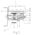
- the accumulation roller conveyor essentially consists of two U-shaped longitudinal beams 2 (see FIG. 3), the open sides of which are facing away from one another. Between and on the webs of the longitudinal members 2, the support rollers 1 are mounted, which form a flat support surface for the material to be conveyed 4 and whose axes of rotation D run transversely to the conveying direction F and horizontally.
- Each support roller 1 can be driven in the direction of rotation d via a drive belt 3 designed as a flat belt.
- the drive belt 3 is designed to run endlessly, the upper run, bearing against the support rollers 1 from below (see FIG. 3), carrying the support rollers 1 by friction.
- This frictional engagement between the drive belt 3 and the support rollers 1 is achieved by lifting the upper run of the drive belt 3 in the direction of the support rollers 1 via support rollers 5, which are seen in the conveying direction F, are each arranged between the successive support rollers 1 and thus in the raised state above the level the lower limit plane formed by the support rollers 1 can also be raised.
- a wave-shaped course of the drive belt 3 seen in side view is achieved and thus through the increased looping of the idlers 1 an optimized transmission of the drive power is achieved.
- an eccentric drive which essentially consists of an eccentric mounting of the support rollers 5 on an axis 6 and a radial to the axis 6 of the support rollers 5 and with the Support rollers 5 connected lever 7 there.
- a linear drive means designed as a pneumatic cylinder and not shown in the drawing engages.
- the support rollers 5 of an accumulation roller conveyor section can be raised and lowered by means of a common linear drive means.
- the respective levers 7 of the support rollers 5 are articulated with their ends to a slide bar 9 which is essentially movable in or against the conveying direction F and which in turn can be moved via the linear drive means.
- each idler roller 1 can be stopped by means of a braking element 10, which is cuboid in shape and is made of polyurethane elastomer.
- the braking elements 10 for two support rollers 1 of a accumulation roller section which follow one another in the conveying direction F are each arranged on a common support element 11 which is designed as a rocker extending in the conveying direction F.
- the two brake elements 10 are fastened on the support element 11 in a form-fitting manner in recesses 12 on the upper side of the support element 11, which correspond to the shape of the brake elements 10.
- the support element 11 is also designed to be raised and lowered via an eccentric drive.
- the eccentric drive essentially consists of an eccentric disk 13, which is mounted eccentrically on the axis 6 and can be pivoted via the lever 7 of the support roller 5.
- the support element 11 designed as a rocker is pivotably mounted in a correspondingly designed opening 14 and the eccentric disc 13 is seen between the in the conveying direction Idlers 1 arranged.
- the pivoting movement of the support element 11 is limited in the rest position moved away from the support rollers 1 by a stop element 8, which is designed as a pin. In the rest position, the stop element 8 lies on the slide bar 9 because the center of gravity S of the support element 11 lies between the stop element 8 and its opening 14. The support element 11 therefore tilts automatically after the brake elements 10 have been released from the support rollers 1 into the rest position.
- the support elements 11 with the brake elements 10 are initially largely movable in the direction of the surfaces of the support rollers 1. Since the support element 11 is arranged slightly tilted forward in the rest position in the conveying direction F, the rear brake element 10 is first set against the support roller 1 and thereby the support element 11 is pivoted about the axis 6, as a result of which the front brake element 10 is also pivoted toward the front support roller 1 is created. With increasing adjustment movement, the brake elements are moved more and more in a direction tangential to the surface of the support rollers 1 and in the direction of rotation thereof, so that in the last area of the adjustment movement the brake elements 10 are clamped between the surfaces of the support rollers 1 and the support element 11. As a result, the contact pressure of the braking elements 10 on the surface of the support rollers 1 is effectively increased.
- the jamming or upsetting of the brake elements 10 is caused by the fact that in the direction of the largely tangential to the surface of the support rollers 1 adjusting movement of the brake elements 10, which in the present case is largely horizontal, the surface of the brake elements 10 facing the support rollers 1 towards the support roller 1 is inclined.
- These boundary conditions are created, inter alia, by the fact that the brake elements 10 with the horizontally running accumulation roller conveyor viewed from below and viewed in the direction of conveyance F from the rear to the support rollers 1.
- the braking effect is favored by the setting of the braking elements 10 in the direction of rotation of the respective support roller 1 by a kind of entrainment effect for the braking element 10, since this increases the clamping effect.
- the support element 11 for the brake elements 10 is additionally displaceable in and against the largely tangential direction of movement of the brake elements 10, i. H. displaceable in or against the direction of conveyance F on the eccentric disc 13.
- the displaceable mounting is realized through an opening 14 in the support element 11 which is designed as an elongated hole and whose longitudinal extension is oriented in or against the conveying direction F.
- FIGS. 1 and 2 each of which shows a side view of a section of an accumulation roller conveyor with support rollers 1 in the unbraked state (see FIG. 1) and in the braked state (see FIG. 2).
- FIGS. 1 and 2 each of which shows a side view of a section of an accumulation roller conveyor with support rollers 1 in the unbraked state (see FIG. 1) and in the braked state (see FIG. 2).
- the slide bar 9 is displaced in the conveying direction F to initiate the braking process via the linear drive means.
- the support rollers 5 and the eccentric discs 13 see in particular FIG.
- the brake elements 10 are moved approximately 3 mm vertically upwards and approximately 1 mm counter to the conveying direction F on a horizontally running accumulation roller conveyor on this circular arc-shaped path.
- the support element 11 At the time when the rear brake element 10 has the first contact with the surface of each support roller 1, the support element 11 is pivoted slightly, the front brake element 10 lies against the associated support roller 1 and the brake elements 10 are transferred from the support rollers 1 Frictionally entrained in their direction of rotation, whereby the support element 11 in its openings 14 designed as an elongated hole suddenly shifted against the conveying direction F on the eccentric discs 13 by about a further 3 mm.
- the brake elements 10 are designed such that they have the effect of wedges, the contact pressure between the brake elements 10 and the surfaces of the support rollers 1 is increased by the additional pushing movement of the support element 11.
- the levers 7 on the axis 6 are given away by approximately 90 ° via the slide bar 9.
- the eccentric discs 13 are rotated in the opposite direction.
- the braking elements 10 on the circular arc-shaped path are released again from the support rollers 1 and the support element 11 slides on the eccentric discs 13 in their openings 14 designed as an elongated hole in the conveying direction F. This movement is determined by the frictional force between the eccentric discs 13 and the opening 14 and causes the horizontal component of the braking force.
- FIG. 3 shows a section through FIGS. 1 and 4 along the section line I-I, that the eccentric discs 13 and the support rollers 5 are mounted on a common axis 6 and each have a common lever 7 on the axis are rotatable.
- FIG. 4 shows a side view of a section of an accumulation roller conveyor in a second embodiment with the braking elements 10 of an accumulation roller section on a common support element 11, which is designed as a strip running in the conveying direction F.
- the remaining features of this embodiment are designed in accordance with FIGS. 1 to 3.
- the brake elements 10 are fastened on the support element 11 in a form-fitting manner in recesses 12 on the upper side of the support element 11, which correspond to the shape of the brake elements 10.
- the support element 11 is also designed to be raised and lowered via eccentric drives.
- two eccentric disks 13 are provided which are spaced apart from one another in the conveying direction and are mounted with correspondingly designed openings 14.
- the support element 11 for the brake elements 10 is additionally in and against the largely tangential Direction of movement of the braking elements 10 is displaceable, ie displaceable in or against the conveying direction F on the eccentric discs 13.
- the displaceable mounting is realized through openings 14 designed as an elongated hole, the longitudinal extent of which is oriented in or against the conveying direction F. So that the support element 11 is in the unbraked state of the accumulation roller conveyor in a defined starting position on the eccentric discs 13, a spring element 15 is provided between the eccentric discs 13 and the support element 11, via which the support element 11 is moved back into the starting position after releasing the braking elements
- FIGS. 4 and 5 show a side view of a section of an accumulation roller conveyor with support rollers 1 in the unbraked state (see FIG. 4) and in the braked state (see FIG. 5).
- the slide bar 9 is displaced in the conveying direction F to initiate the braking process via the linear drive means.
- the support rollers 5 and the eccentric disks 13 see in particular FIG.
- the brake elements 10 are designed such that they have the effect of wedges, the contact pressure between the brake elements 10 and the surfaces of the support rollers 1 is increased by the additional thrust movement of the support element 11.
- the levers 7 on the axis 6 are given away by approximately 90 ° via the slide bar 9.
- the eccentric discs 13 are rotated in the opposite direction.
- the brake elements 10 on the circular arc-shaped path are released again from the support rollers 1 and the support element slides on the eccentric discs 13 in their openings 14 designed as an elongated hole in the conveying direction F. This movement is effected via the spring elements 15.
Landscapes
- Engineering & Computer Science (AREA)
- Mechanical Engineering (AREA)
- Rollers For Roller Conveyors For Transfer (AREA)
- Rolls And Other Rotary Bodies (AREA)
- Attitude Control For Articles On Conveyors (AREA)
- Braking Arrangements (AREA)
Applications Claiming Priority (4)
| Application Number | Priority Date | Filing Date | Title |
|---|---|---|---|
| DE19619097 | 1996-05-06 | ||
| DE19619097 | 1996-05-06 | ||
| DE19628711A DE19628711C2 (de) | 1996-05-06 | 1996-07-08 | Staurollenbahn |
| DE19628711 | 1996-07-08 |
Publications (2)
| Publication Number | Publication Date |
|---|---|
| EP0806376A1 true EP0806376A1 (fr) | 1997-11-12 |
| EP0806376B1 EP0806376B1 (fr) | 2001-05-23 |
Family
ID=26025629
Family Applications (2)
| Application Number | Title | Priority Date | Filing Date |
|---|---|---|---|
| EP96250210A Expired - Lifetime EP0806376B1 (fr) | 1996-05-06 | 1996-09-25 | Transporteur à rouleaux avec rouleaux supports pour les objets transportés |
| EP97250144A Expired - Lifetime EP0806377B1 (fr) | 1996-05-06 | 1997-04-28 | Convoyeur accumulateur à rouleaux |
Family Applications After (1)
| Application Number | Title | Priority Date | Filing Date |
|---|---|---|---|
| EP97250144A Expired - Lifetime EP0806377B1 (fr) | 1996-05-06 | 1997-04-28 | Convoyeur accumulateur à rouleaux |
Country Status (3)
| Country | Link |
|---|---|
| EP (2) | EP0806376B1 (fr) |
| AT (2) | ATE201375T1 (fr) |
| DK (2) | DK0806376T3 (fr) |
Cited By (1)
| Publication number | Priority date | Publication date | Assignee | Title |
|---|---|---|---|---|
| CN114803279A (zh) * | 2022-04-25 | 2022-07-29 | 老肯医疗科技股份有限公司 | 一种清洗架输送系统及其输送方法 |
Families Citing this family (1)
| Publication number | Priority date | Publication date | Assignee | Title |
|---|---|---|---|---|
| CN115648328B (zh) * | 2022-09-30 | 2023-09-01 | 连云港师达工艺品有限公司 | 一种带有废料收集机构的eva片材切割装置及其收集方法 |
Citations (8)
| Publication number | Priority date | Publication date | Assignee | Title |
|---|---|---|---|---|
| DE2550143A1 (de) * | 1974-11-11 | 1976-05-20 | Alvey Inc | Foerdereinrichtung fuer foerderrollen |
| FR2537104A1 (fr) * | 1982-12-03 | 1984-06-08 | Gallet Sa | Transporteur a rouleaux commandes comportant un systeme de debrayage et de freins |
| DE3418205A1 (de) * | 1984-05-16 | 1985-11-21 | psb GmbH Förderanlagen und Lagertechnik, 6780 Pirmasens | Staurollenfoerderer |
| AT384595B (de) * | 1983-03-24 | 1987-12-10 | Tgw Transportgeraete Gmbh | Rollenbahn |
| DE3817388C1 (fr) | 1988-05-19 | 1989-07-06 | Mannesmann Ag, 4000 Duesseldorf, De | |
| DE3738587C2 (fr) | 1987-11-13 | 1993-08-05 | Khs Verpackungstechnik Gmbh, 4600 Dortmund, De | |
| EP0640540A1 (fr) * | 1993-08-31 | 1995-03-01 | Steiff Fördertechnik GmbH | Dispositif et procédé pour convoyer des articles sur des rouleaux parallèles et à émerillon rotatif |
| DE4409968A1 (de) | 1994-03-23 | 1995-09-28 | Gebhardt Foerdertech | Bausatz zum Bremsen der Tragrollen von Rollenförderern |
-
1996
- 1996-09-25 AT AT96250210T patent/ATE201375T1/de not_active IP Right Cessation
- 1996-09-25 EP EP96250210A patent/EP0806376B1/fr not_active Expired - Lifetime
- 1996-09-25 DK DK96250210T patent/DK0806376T3/da active
-
1997
- 1997-04-28 EP EP97250144A patent/EP0806377B1/fr not_active Expired - Lifetime
- 1997-04-28 AT AT97250144T patent/ATE200064T1/de active
- 1997-04-28 DK DK97250144T patent/DK0806377T3/da active
Patent Citations (8)
| Publication number | Priority date | Publication date | Assignee | Title |
|---|---|---|---|---|
| DE2550143A1 (de) * | 1974-11-11 | 1976-05-20 | Alvey Inc | Foerdereinrichtung fuer foerderrollen |
| FR2537104A1 (fr) * | 1982-12-03 | 1984-06-08 | Gallet Sa | Transporteur a rouleaux commandes comportant un systeme de debrayage et de freins |
| AT384595B (de) * | 1983-03-24 | 1987-12-10 | Tgw Transportgeraete Gmbh | Rollenbahn |
| DE3418205A1 (de) * | 1984-05-16 | 1985-11-21 | psb GmbH Förderanlagen und Lagertechnik, 6780 Pirmasens | Staurollenfoerderer |
| DE3738587C2 (fr) | 1987-11-13 | 1993-08-05 | Khs Verpackungstechnik Gmbh, 4600 Dortmund, De | |
| DE3817388C1 (fr) | 1988-05-19 | 1989-07-06 | Mannesmann Ag, 4000 Duesseldorf, De | |
| EP0640540A1 (fr) * | 1993-08-31 | 1995-03-01 | Steiff Fördertechnik GmbH | Dispositif et procédé pour convoyer des articles sur des rouleaux parallèles et à émerillon rotatif |
| DE4409968A1 (de) | 1994-03-23 | 1995-09-28 | Gebhardt Foerdertech | Bausatz zum Bremsen der Tragrollen von Rollenförderern |
Cited By (2)
| Publication number | Priority date | Publication date | Assignee | Title |
|---|---|---|---|---|
| CN114803279A (zh) * | 2022-04-25 | 2022-07-29 | 老肯医疗科技股份有限公司 | 一种清洗架输送系统及其输送方法 |
| CN114803279B (zh) * | 2022-04-25 | 2023-09-22 | 老肯医疗科技股份有限公司 | 一种清洗架输送系统及其输送方法 |
Also Published As
| Publication number | Publication date |
|---|---|
| ATE200064T1 (de) | 2001-04-15 |
| EP0806377A1 (fr) | 1997-11-12 |
| DK0806377T3 (da) | 2001-04-30 |
| EP0806377B1 (fr) | 2001-03-28 |
| ATE201375T1 (de) | 2001-06-15 |
| DK0806376T3 (da) | 2001-08-06 |
| EP0806376B1 (fr) | 2001-05-23 |
Similar Documents
| Publication | Publication Date | Title |
|---|---|---|
| AT414329B (de) | Übergabeeinrichtung für stückhaftes fördergut | |
| WO1986002622A1 (fr) | Transporteur a chaine pour pieces a usiner ou pour supports de pieces a usiner | |
| CH666013A5 (de) | Foerdereinrichtung fuer werkstuecke bzw. werkstuecktraeger, insbesondere fuer eine montagemaschine. | |
| DE3202382C2 (de) | Reversierbare Stauförderbahn | |
| EP1811194B1 (fr) | Frein à disque | |
| DE10020909B4 (de) | Vorrichtung zur Förderung einer Vorratsrolle | |
| EP0760061B1 (fr) | Dispositif de serrage pour frein a disque | |
| EP3546399B1 (fr) | Dispositif de levage et de transport et transporteur à vis doté du dispositif de levage et de transport | |
| EP0161412B1 (fr) | Dispositif de transport pour convoyer des montages supports de pièces | |
| EP0806376A1 (fr) | Transporteur à rouleaux avec rouleaux supports pour les objets transportés | |
| AT384595B (de) | Rollenbahn | |
| DE19628711C2 (de) | Staurollenbahn | |
| DE3820328C2 (de) | Bremse für einen OE-Spinnrotor | |
| DE19850678C1 (de) | Doppel-Bremsfangvorrichtung für Aufzüge oder Regalbediengeräte (RBG) | |
| DE3812863C2 (fr) | ||
| DE10204260A1 (de) | Stauförderer | |
| DE69504443T2 (de) | Einspannvorrichtung | |
| DE3134577A1 (de) | Elektrische schneidmaschine | |
| DE2717482C3 (de) | Verfahren und Vorrichtung zum Stoppen von sich auf einer Rollenbahn bewegendem Transportgut an einer Stoppstelle | |
| CH670239A5 (fr) | ||
| DE2331590C3 (de) | Lastdruckbremse für einen Hebezeugantrieb | |
| DE19610640C2 (de) | Gefällerollenbahn mit Bremsrollen | |
| DE19852040C1 (de) | Doppel-Bremsfangvorrichtung für Aufzüge oder Regalbediengeräte (RBG) | |
| DE19619096C2 (de) | Gefällerollenbahn mit gebremsten Rollen | |
| DE19940059C2 (de) | Doppel-Bremsfangvorrichtung für Aufzüge oder Regalbediengeräte (RBG) |
Legal Events
| Date | Code | Title | Description |
|---|---|---|---|
| PUAI | Public reference made under article 153(3) epc to a published international application that has entered the european phase |
Free format text: ORIGINAL CODE: 0009012 |
|
| AK | Designated contracting states |
Kind code of ref document: A1 Designated state(s): AT DE DK FR GB IT NL |
|
| 17P | Request for examination filed |
Effective date: 19971113 |
|
| 17Q | First examination report despatched |
Effective date: 19990329 |
|
| GRAG | Despatch of communication of intention to grant |
Free format text: ORIGINAL CODE: EPIDOS AGRA |
|
| GRAG | Despatch of communication of intention to grant |
Free format text: ORIGINAL CODE: EPIDOS AGRA |
|
| GRAH | Despatch of communication of intention to grant a patent |
Free format text: ORIGINAL CODE: EPIDOS IGRA |
|
| RAP1 | Party data changed (applicant data changed or rights of an application transferred) |
Owner name: ATECS MANNESMANN AG |
|
| GRAH | Despatch of communication of intention to grant a patent |
Free format text: ORIGINAL CODE: EPIDOS IGRA |
|
| GRAA | (expected) grant |
Free format text: ORIGINAL CODE: 0009210 |
|
| AK | Designated contracting states |
Kind code of ref document: B1 Designated state(s): AT DE DK FR GB IT NL |
|
| REF | Corresponds to: |
Ref document number: 201375 Country of ref document: AT Date of ref document: 20010615 Kind code of ref document: T |
|
| GBT | Gb: translation of ep patent filed (gb section 77(6)(a)/1977) |
Effective date: 20010523 |
|
| REF | Corresponds to: |
Ref document number: 59606961 Country of ref document: DE Date of ref document: 20010628 |
|
| ITF | It: translation for a ep patent filed | ||
| REG | Reference to a national code |
Ref country code: DK Ref legal event code: T3 |
|
| ET | Fr: translation filed | ||
| REG | Reference to a national code |
Ref country code: GB Ref legal event code: IF02 |
|
| PLBE | No opposition filed within time limit |
Free format text: ORIGINAL CODE: 0009261 |
|
| STAA | Information on the status of an ep patent application or granted ep patent |
Free format text: STATUS: NO OPPOSITION FILED WITHIN TIME LIMIT |
|
| 26N | No opposition filed | ||
| PGFP | Annual fee paid to national office [announced via postgrant information from national office to epo] |
Ref country code: DE Payment date: 20041118 Year of fee payment: 9 |
|
| PGFP | Annual fee paid to national office [announced via postgrant information from national office to epo] |
Ref country code: NL Payment date: 20050905 Year of fee payment: 10 Ref country code: DK Payment date: 20050905 Year of fee payment: 10 |
|
| PGFP | Annual fee paid to national office [announced via postgrant information from national office to epo] |
Ref country code: GB Payment date: 20050906 Year of fee payment: 10 |
|
| PGFP | Annual fee paid to national office [announced via postgrant information from national office to epo] |
Ref country code: AT Payment date: 20050907 Year of fee payment: 10 |
|
| PGFP | Annual fee paid to national office [announced via postgrant information from national office to epo] |
Ref country code: FR Payment date: 20050912 Year of fee payment: 10 |
|
| PG25 | Lapsed in a contracting state [announced via postgrant information from national office to epo] |
Ref country code: DE Free format text: LAPSE BECAUSE OF NON-PAYMENT OF DUE FEES Effective date: 20060401 |
|
| PG25 | Lapsed in a contracting state [announced via postgrant information from national office to epo] |
Ref country code: AT Free format text: LAPSE BECAUSE OF NON-PAYMENT OF DUE FEES Effective date: 20060925 |
|
| PGFP | Annual fee paid to national office [announced via postgrant information from national office to epo] |
Ref country code: IT Payment date: 20060930 Year of fee payment: 11 |
|
| PG25 | Lapsed in a contracting state [announced via postgrant information from national office to epo] |
Ref country code: DK Free format text: LAPSE BECAUSE OF NON-PAYMENT OF DUE FEES Effective date: 20061002 |
|
| PG25 | Lapsed in a contracting state [announced via postgrant information from national office to epo] |
Ref country code: NL Free format text: LAPSE BECAUSE OF NON-PAYMENT OF DUE FEES Effective date: 20070401 |
|
| REG | Reference to a national code |
Ref country code: DK Ref legal event code: EBP |
|
| GBPC | Gb: european patent ceased through non-payment of renewal fee |
Effective date: 20060925 |
|
| NLV4 | Nl: lapsed or anulled due to non-payment of the annual fee |
Effective date: 20070401 |
|
| REG | Reference to a national code |
Ref country code: FR Ref legal event code: ST Effective date: 20070531 |
|
| PG25 | Lapsed in a contracting state [announced via postgrant information from national office to epo] |
Ref country code: GB Free format text: LAPSE BECAUSE OF NON-PAYMENT OF DUE FEES Effective date: 20060925 |
|
| PG25 | Lapsed in a contracting state [announced via postgrant information from national office to epo] |
Ref country code: FR Free format text: LAPSE BECAUSE OF NON-PAYMENT OF DUE FEES Effective date: 20061002 |
|
| PG25 | Lapsed in a contracting state [announced via postgrant information from national office to epo] |
Ref country code: IT Free format text: LAPSE BECAUSE OF NON-PAYMENT OF DUE FEES Effective date: 20070925 |