EP0806388A1 - Verfahren und Einheit zum Bilden und Fördern von Gruppen von Gegenständen - Google Patents
Verfahren und Einheit zum Bilden und Fördern von Gruppen von Gegenständen Download PDFInfo
- Publication number
- EP0806388A1 EP0806388A1 EP97107562A EP97107562A EP0806388A1 EP 0806388 A1 EP0806388 A1 EP 0806388A1 EP 97107562 A EP97107562 A EP 97107562A EP 97107562 A EP97107562 A EP 97107562A EP 0806388 A1 EP0806388 A1 EP 0806388A1
- Authority
- EP
- European Patent Office
- Prior art keywords
- group
- conveying
- along
- path
- Prior art date
- Legal status (The legal status is an assumption and is not a legal conclusion. Google has not performed a legal analysis and makes no representation as to the accuracy of the status listed.)
- Granted
Links
- 238000000034 method Methods 0.000 title claims abstract description 19
- 230000002093 peripheral effect Effects 0.000 claims description 4
- 230000015572 biosynthetic process Effects 0.000 description 1
- 230000001052 transient effect Effects 0.000 description 1
- 238000011144 upstream manufacturing Methods 0.000 description 1
Images
Classifications
-
- B—PERFORMING OPERATIONS; TRANSPORTING
- B65—CONVEYING; PACKING; STORING; HANDLING THIN OR FILAMENTARY MATERIAL
- B65G—TRANSPORT OR STORAGE DEVICES, e.g. CONVEYORS FOR LOADING OR TIPPING, SHOP CONVEYOR SYSTEMS OR PNEUMATIC TUBE CONVEYORS
- B65G57/00—Stacking of articles
- B65G57/30—Stacking of articles by adding to the bottom of the stack
- B65G57/305—Stacking of articles by adding to the bottom of the stack by means of rotary devices or endless elements
- B65G57/307—Stacking of articles by adding to the bottom of the stack by means of rotary devices or endless elements the rotary devices being screws
Definitions
- the present invention relates to a method of forming and conveying groups of products.
- the present invention relates to a method of forming and conveying groups of elongated products, the method comprising the steps of feeding said products successively and continuously along a first path to a stacking device; stacking the products, by means of the stacking device, along guide elements to form a group, the products in the group being maintained in the stacked position by the guide elements; and transferring the group along a second path into a respective conveying pocket moving along the second path.
- Methods of the above type are normally implemented using stacking devices in which the guide elements, besides maintaining the products in the stacked position as they are being stacked, also provide for feeding each group of stacked products to a conveying device, which comprises a conveying surface extending along the second path, and a conveying element for feeding each group along the conveying surface.
- the group of products is normally unloaded onto the conveying surface by the guide elements and subsequently engaged and fed along the conveying surface by the conveying element.
- a method of forming and conveying groups of elongated products comprising the steps of feeding said products successively and continuously along a first path to a stacking device; stacking said products, by means of said stacking device, along guide means to form a group, said guide means maintaining the products in said group in a stacked position; and transferring said group along a second path into a respective conveying pocket moving along the second path; the method being characterized in that said group is transferred to the conveying pocket by means of a retaining pocket moving in steps along said second path and through a position of alignment with said group on said stacking device.
- the present invention also relates to a unit for forming and conveying groups of elongated products.
- a unit for forming and conveying groups of elongated products comprising supply means for feeding said products successively and continuously along a first path to a stacking station; a stacking device located at the stacking station, and for stacking said products into a group; guide means located at the stacking station to maintain the products in said group in a stacked position; transfer means for transferring said group along a second path; and conveying means having conveying pockets moving along the second path, and each for receiving a respective group; the unit being characterized in that said transfer means comprise at least one retaining pocket moving in steps along said second path and through a position of alignment with said group on said stacking device, and through a transfer station to transfer the group to a respective conveying pocket.
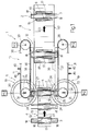
- Number 1 in Figures 1 and 2 indicates a unit for forming and conveying groups 2 of elongated products 3 preferably, but not necessarily, having a substantially circular cross section.
- Unit 1 comprises a supply device 4 for feeding products 3 successively and continuously in a traveling direction D1 crosswise to products 3, and along a path P1 extending through a stacking station 5.
- Unit 1 also comprises a stacking device 6 located at station 5, and for receiving products 3 from device 4, stacking products 3 in a stacking direction D2 substantially crosswise to direction D1, and forming a group 2 of products 3 along a guide 7 extending in direction D2 and for maintaining products 3 in group 2 in a stacked position.
- Unit 1 also comprises a conveying device 8, in turn comprising a number of conveying pockets 9 for feeding groups 2 in a direction D3 crosswise to direction D2, and along a further path P2 substantially in series with path P1; and a transfer device 10 located along path P2, between stacking device 6 and conveying device 8, and in turn comprising a number of retaining pockets 11 for receiving groups 2 from stacking device 6 and feeding groups 2 to conveying device 8 via a transfer station 12 located along path P2, between devices 8 and 10, while at the same time maintaining groups 2 in the stacked position.
- a conveying device 8 in turn comprising a number of conveying pockets 9 for feeding groups 2 in a direction D3 crosswise to direction D2, and along a further path P2 substantially in series with path P1
- a transfer device 10 located along path P2, between stacking device 6 and conveying device 8, and in turn comprising a number of retaining pockets 11 for receiving groups 2 from stacking device 6 and feeding groups 2 to conveying device 8 via a transfer station 12 located along path P2, between devices 8
- Device 4 comprises a pocket conveyor belt 13 looped about two pulleys 14 (only one shown), which define on belt 13 a conveying branch 15 extending along path P1; and belt 13 comprises a number of pockets 16 extending crosswise to direction D1, and each for housing a respective product 3 with its central portion 17 inside pocket 16, and its lateral end portions 18 projecting outwards of pocket 16 and branch 15.
- Stacking device 6 comprises two screw conveyors 19 located on either side of branch 15, and each having a respective screw 20 rotating continuously about a respective axis 21 parallel to direction D2. Screws 20 are oppositely inclined, and are positioned with their respective bottom ends 22 substantially tangent to branch 15 of belt 13, so as to successively engage lateral end portions 18 of products 3, and feed products 3 in direction D2 by lifting products 3 off branch 15 and by cooperating with guide 7 to stack products 3 on respective top ends 23.
- guide 7 comprises two substantially C-shaped plates 24 located on either side of branch 15, and each having two vertical walls 25 and 26 located in series with each other in direction D1, and extending in direction D2 to define a respective channel 27 for the passage of a respective lateral end portion 18 of product 3.
- Each wall 25 has a bottom front opening 28 lower than the top end 23 of respective screw 20 and facing branch 15 of belt 13 so as to be engaged by respective lateral end portion 18 of product 3; and each wall 26 comprises a stop portion 29 facing opening 28 in corresponding wall 25, and which arrests the travel of product 3 in direction D1, and cooperates with respective screw 20 to lead product 3 in direction D2 with respective lateral end portion 18 engaged in sliding manner inside respective channel 27.
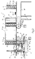
- Transfer device 10 comprises two conveyor belts 30 and 31 facing each other on either side of path P2, of a width approximately equal to but no less than the height of a group 2, and looped about respective pairs of pulleys 32,33 and 34,35 having respective axes of rotation parallel to direction D2.
- Pulleys 32 and 34 are located over screws 20, substantially at axes 21; while pulleys 33 and 35 are located on either side of conveying device 8, and define on respective belts 30 and 31, together with respective pulleys 32 and 34, respective forward branches 36 and 37 of belts 30 and 31.
- Branches 36 and 37 are separated by a distance equal to the length of products 3, and extend over respective guide plates 38 and 39, which are coplanar with each other along path P2, are connected to the top ends of respective walls 26 of plates 24, and support groups 2 housed inside pockets 11 by cooperating with respective lateral end portions 18 of the last product 3 in each group 2.
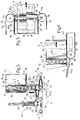
- Each belt 30, 31 comprises a number of pairs of outer projections 40 defining retaining pockets 11, and which are alignable with respective walls 25 and 26 ( Figure 3) so that respective pocket 11 is aligned with channels 27 of guide 7 and defines a movable portion of guide 7.
- each pocket 11 receives a share of products 3 of each group 2 during the formation of group 2, which, when completed, is inserted fully inside pocket 11 by a lifting device 41 located over branch 15 of belt 13, in front of walls 25 of guide 7.
- Lifting device 41 comprises two tubular guide elements 42 parallel to direction D2; and a slide 43, which, by means of a linear actuator 44, is moved along tubular elements 42 between a lowered position ( Figure 3) substantially facing front openings 28 in walls 25, and a raised position (not shown) substantially aligned with plates 38 and 39.
- Device 41 also comprises a lifting plate 45 fitted to slide 43, and which, by means of a respective linear actuator 46 integral with slide 43, is movable in direction D1 between a position of interference ( Figure 3) in which plate 45 is located between plates 24 and beneath and contacting central portion 17 of the last product 3 in group 2, and an idle position (shown by the dotted line in Figure 2) in which plate 45 is located over branch 15 of belt 13 and outside guide 7.
- plate 45 is moved from the idle to the interference position when, in use, slide 43 is set to the lowered position, so as to support a newly completed group 2; provides for inserting group 2 inside respective pocket 11 as slide 43 moves from the lowered to the raised position aligned with plates 38 and 39; and is restored to the idle position upon group 2 being fed by device 10 along path P2.
- Conveying device 8 comprises a respective conveyor belt 47 narrower than the length of products 3, located between belts 30 and 31, and looped about two pulleys 48 (only one shown), which have respective horizontal axes of rotation crosswise to direction D3, and are fitted to a slide (not shown) to move parallel to themselves, as explained in detail later on, by virtue of a linear actuator 49, the output rod 50 of which is movable in direction D3 and connected to the pulley 48 shown.
- Belt 47 comprises a number of pairs of peripheral elongated projections 51 extending outwards of belt 47 and defining conveying pockets 9.
- Projections 51 are narrower than the length of products 3, so that products 3 are housed inside pockets 9 with respective central portions 17 inside pockets 9, and with respective lateral end portions 18 projecting outwards of pockets 9; are longer than the height of groups 2, so that each pocket 9 receives and maintains a respective group 2 in the stacked position; and are shorter than the spacing J of pockets 11 along belts 30, 31, i.e. are shorter than the distance between two successive projections 40 of two different pockets 11.
- unit 1 Operation of unit 1 is controlled by a known central control unit (not shown), which receives signals from a known sensor (not shown) located along guide 7 to determine completion of group 2, and from at least a further known sensor (not shown) located at station 12 to determine the arrival in station 12 of groups 2.
- a known central control unit not shown
- the central control unit in turn generates output signals for controlling a motor M1 angularly integral with pulley 14 of supply device 4; two motors M2 angularly integral with screws 20 of stacking device 6; actuators 44 and 46 of lifting device 41; two motors M3 angularly integral with pulleys 33 and 35 of transfer device 10; a motor M4 angularly integral with pulley 48; and actuator 49 of conveying device 8.
- Motors M3 and M4 are related to one another by an electric timing axis for ensuring respective pockets 11 and 9 are not only fed at the same speed V1 along path P2, but are also fed in steps and in time with one another through station 12 to transfer groups 2 at station 12.
- unit 1 Operation of unit 1 will now be described with reference to groups 2 each comprising, by way of example, five products 3, and as of the instant in which guide 7 is empty; a pocket 11 is arrested by transfer device 10 in the aligned position with guide 7; and plate 45 is set to the idle position with slide 43 in the lowered position.
- conveyor belt 13 of supply device 4 supplies stacking station 5 with successive products 3, which, just before contacting stop portions 29 of walls 26, are engaged by the bottom ends 22 of screws 20, which, besides lifting products 3 out of pockets 16 in direction D2, cooperate with walls 25 and 26 of plates 24 to feed products 3 into guide 7 in direction D2, stack products 3 one beneath the other, and so form a group 2.
- group 2 is formed both inside a fixed portion 52 of guide 7 defined by the portions of walls 25 and 26 extending above the point through which respective top ends 23 of screws 20 travel, and inside the movable portion of guide 7 defined, as stated, by a pocket 11 in the aligned position.
- lifting device 41 is activated by the central control unit to insert group 2 fully inside respective pocket 11. More specifically, actuator 46 moves plate 45 from the idle position to the interference position beneath central portion 17 of the last product 3 forming group 2, and actuator 44 moves slide 43 in direction D2 to lift group 2 in direction D2 and align plate 45 with plates 38 and 39.
- group 2 is housed entirely inside respective pocket 11, with the lateral end portions 18 of products 3 secured firmly by respective pairs of projections 40 to prevent group 2 from breaking up.
- the central control unit activates both motors M3 and motor M4 to feed respective pockets 11 and 9 in direction D3 at the same speed V1.
- group 2 is moved out of stacking station 5
- plate 45 is unloaded and reset to the idle position, and plates 38 and 39 are subsequently engaged by respective lateral end portions 18 of said last product 3.
- a pocket 9 is located astride pulley 48, with respective elongated projections 51 diverging and extending radially outwards from pulley 48. More specifically, the first projection 51 to travel about pulley 48 (projection 51a) is located substantially in front of group 2 and ahead of respective pocket 11 in direction D3, while the second projection 51 to travel about pulley 48 (projection 51b) is located substantially beneath group 2 and behind respective pocket 11.
- the central control unit operates actuator 49 to move pulleys 48 of belt 47 in the opposite direction to the traveling direction D3 of pockets 9 and 11 and at a speed equal to speed V1, so as to bring projection 51a up to group 2 as projection 51a rotates about pulley 48. More specifically, as a result of pulleys 48 and belt 47 being moved simultaneously in opposite directions, the point at which projection 51a is joined to belt 47 is arrested temporarily so that projection 51a rotates about said point, and projection 51b is rotated faster about pulley 48 and so positioned directly behind group 2; in this way each pocket 9 gradually envelops the group 2 still housed inside pocket 11.
- spacing J is such that, when group 2 is locked inside both pocket 11 and pocket 9, a further pocket 11 is aligned with guide 7.
- the central control unit Upon a further group 2 being completed, the central control unit reactivates motors M3 and M4 to finally unload the previous group 2 from pocket 11 into pocket 9.
- Group 2 is unloaded from respective pocket 11 into respective pocket 9 at pulleys 33 and 35 of transfer device 10. That is, as belts 30, 31 rotate about respective pulleys 33, 35, the first projections 40 (40a) to reach pulleys 33, 35 are moved away from the second projections 40 (40b) to reach pulleys 33, 35, and a relative speed is determined between pockets 11 and 9.
- projections 40 diverge to open respective pocket 11 and release respective group 2, which, being by now firmly housed inside pocket 9, is withdrawn from pocket 11 by pocket 9 and fed further along path P2.
- projections 40 and 51 therefore provide for maintaining the products 3 in group 2 firmly in the stacked position, so that unit 1 may advantageously be used for forming and conveying groups 2 of stacked products 3 in general, regardless of the shape of products 3, i.e. even substantially irregularly shaped products 3 incapable of remaining stacked on their own.
Landscapes
- Engineering & Computer Science (AREA)
- Mechanical Engineering (AREA)
- Attitude Control For Articles On Conveyors (AREA)
Applications Claiming Priority (2)
| Application Number | Priority Date | Filing Date | Title |
|---|---|---|---|
| ITBO960256 | 1996-05-08 | ||
| IT96BO000256A IT1285694B1 (it) | 1996-05-08 | 1996-05-08 | Metodo ed unita' per la formazione ed il convogliamento di gruppi di prodotti |
Publications (2)
| Publication Number | Publication Date |
|---|---|
| EP0806388A1 true EP0806388A1 (de) | 1997-11-12 |
| EP0806388B1 EP0806388B1 (de) | 2002-09-04 |
Family
ID=11341392
Family Applications (1)
| Application Number | Title | Priority Date | Filing Date |
|---|---|---|---|
| EP97107562A Expired - Lifetime EP0806388B1 (de) | 1996-05-08 | 1997-05-07 | Verfahren und Einheit zum Bilden und Fördern von Gruppen von Gegenständen |
Country Status (4)
| Country | Link |
|---|---|
| US (1) | US5887701A (de) |
| EP (1) | EP0806388B1 (de) |
| DE (1) | DE69715080T2 (de) |
| IT (1) | IT1285694B1 (de) |
Cited By (3)
| Publication number | Priority date | Publication date | Assignee | Title |
|---|---|---|---|---|
| EP0905065A1 (de) * | 1997-09-25 | 1999-03-31 | AZIONARIA COSTRUZIONI MACCHINE AUTOMATICHE-A.C.M.A.-S.p.A. | Einheit zum Bilden und Befördern von Gegenstandsstapeln zu einer Maschine |
| EP0953527A1 (de) * | 1998-02-25 | 1999-11-03 | AZIONARIA COSTRUZIONI MACCHINE AUTOMATICHE-A.C.M.A.-S.p.A. | Vorrichtung zum Bilden von Stapeln von Gegenständen |
| WO2003040004A1 (en) * | 2001-11-05 | 2003-05-15 | G.D Societa' Per Azioni | Variable-capacity store for packets of cigarettes |
Families Citing this family (13)
| Publication number | Priority date | Publication date | Assignee | Title |
|---|---|---|---|---|
| IT1299948B1 (it) * | 1998-04-02 | 2000-04-04 | Azionaria Costruzioni Acma Spa | Metodo e dispositivo per la formazione di gruppi di articoli appiattiti. |
| US7506746B2 (en) * | 2002-08-31 | 2009-03-24 | Applied Materials, Inc. | System for transporting substrate carriers |
| US7930061B2 (en) * | 2002-08-31 | 2011-04-19 | Applied Materials, Inc. | Methods and apparatus for loading and unloading substrate carriers on moving conveyors using feedback |
| US20050095110A1 (en) * | 2002-08-31 | 2005-05-05 | Lowrance Robert B. | Method and apparatus for unloading substrate carriers from substrate carrier transport system |
| US7243003B2 (en) * | 2002-08-31 | 2007-07-10 | Applied Materials, Inc. | Substrate carrier handler that unloads substrate carriers directly from a moving conveyor |
| US7234584B2 (en) * | 2002-08-31 | 2007-06-26 | Applied Materials, Inc. | System for transporting substrate carriers |
| US7684895B2 (en) | 2002-08-31 | 2010-03-23 | Applied Materials, Inc. | Wafer loading station that automatically retracts from a moving conveyor in response to an unscheduled event |
| US20040081546A1 (en) | 2002-08-31 | 2004-04-29 | Applied Materials, Inc. | Method and apparatus for supplying substrates to a processing tool |
| US7077264B2 (en) | 2003-01-27 | 2006-07-18 | Applied Material, Inc. | Methods and apparatus for transporting substrate carriers |
| US20070258796A1 (en) * | 2006-04-26 | 2007-11-08 | Englhardt Eric A | Methods and apparatus for transporting substrate carriers |
| WO2009055395A1 (en) | 2007-10-22 | 2009-04-30 | Applied Materials, Inc. | Methods and apparatus for transporting substrate carriers |
| JP4474618B2 (ja) * | 2008-03-18 | 2010-06-09 | オリオン機械工業株式会社 | 製品集積装置 |
| CN106915623A (zh) * | 2017-03-17 | 2017-07-04 | 深圳市宇星鸿精密科技有限公司 | 激光雕刻自动上料设备 |
Citations (5)
| Publication number | Priority date | Publication date | Assignee | Title |
|---|---|---|---|---|
| DE1127810B (de) * | 1960-12-21 | 1962-04-12 | Hesser Ag Maschf | Vorrichtung zum Stapeln von prismatischen Gegenstaenden, insbesondere in Verbindung mit einer Einrichtung zum Sammelpacken der gestapelten Gegenstaende |
| FR2320877A1 (fr) * | 1975-08-14 | 1977-03-11 | Molins Ltd | Dispositif pour manipuler les objets en forme de tiges, tels que des cigarettes |
| US4314785A (en) * | 1979-12-26 | 1982-02-09 | Package Machinery Company | Stacking and packaging apparatus |
| EP0396995A1 (de) * | 1989-05-12 | 1990-11-14 | Focke & Co. (GmbH & Co.) | Vorrichtung zum Heben von Gegenständen, insbesondere von Packungen zur Bildung von abförderbaren Stapeln |
| EP0403956A1 (de) * | 1989-06-17 | 1990-12-27 | SANJO MACHINE WORKS, Ltd. | Apparat zum Stapeln und Fördern |
Family Cites Families (3)
| Publication number | Priority date | Publication date | Assignee | Title |
|---|---|---|---|---|
| GB1436113A (en) * | 1972-04-26 | 1976-05-19 | Albright & Wilson | Purification of phosphoric acid |
| US4502587A (en) * | 1983-04-18 | 1985-03-05 | R. J. Reynolds Tobacco Company | Automatic accumulator for rectangular articles |
| US5579894A (en) * | 1995-04-11 | 1996-12-03 | R. A. Jones & Co. Inc. | Direct drop transfer apparatus |
-
1996
- 1996-05-08 IT IT96BO000256A patent/IT1285694B1/it active IP Right Grant
-
1997
- 1997-05-07 DE DE69715080T patent/DE69715080T2/de not_active Expired - Fee Related
- 1997-05-07 US US08/852,391 patent/US5887701A/en not_active Expired - Fee Related
- 1997-05-07 EP EP97107562A patent/EP0806388B1/de not_active Expired - Lifetime
Patent Citations (5)
| Publication number | Priority date | Publication date | Assignee | Title |
|---|---|---|---|---|
| DE1127810B (de) * | 1960-12-21 | 1962-04-12 | Hesser Ag Maschf | Vorrichtung zum Stapeln von prismatischen Gegenstaenden, insbesondere in Verbindung mit einer Einrichtung zum Sammelpacken der gestapelten Gegenstaende |
| FR2320877A1 (fr) * | 1975-08-14 | 1977-03-11 | Molins Ltd | Dispositif pour manipuler les objets en forme de tiges, tels que des cigarettes |
| US4314785A (en) * | 1979-12-26 | 1982-02-09 | Package Machinery Company | Stacking and packaging apparatus |
| EP0396995A1 (de) * | 1989-05-12 | 1990-11-14 | Focke & Co. (GmbH & Co.) | Vorrichtung zum Heben von Gegenständen, insbesondere von Packungen zur Bildung von abförderbaren Stapeln |
| EP0403956A1 (de) * | 1989-06-17 | 1990-12-27 | SANJO MACHINE WORKS, Ltd. | Apparat zum Stapeln und Fördern |
Cited By (5)
| Publication number | Priority date | Publication date | Assignee | Title |
|---|---|---|---|---|
| EP0905065A1 (de) * | 1997-09-25 | 1999-03-31 | AZIONARIA COSTRUZIONI MACCHINE AUTOMATICHE-A.C.M.A.-S.p.A. | Einheit zum Bilden und Befördern von Gegenstandsstapeln zu einer Maschine |
| US6089820A (en) * | 1997-09-25 | 2000-07-18 | Azionaria Costruzioni Macchine Automatiche A.C.M.A. S.P.A. | Unit for forming and supplying stacks of products to a machine |
| EP0953527A1 (de) * | 1998-02-25 | 1999-11-03 | AZIONARIA COSTRUZIONI MACCHINE AUTOMATICHE-A.C.M.A.-S.p.A. | Vorrichtung zum Bilden von Stapeln von Gegenständen |
| US6155774A (en) * | 1998-02-25 | 2000-12-05 | Azionaria Costruzioni Macchine Automatiche A.C.M.A. S.P.A. | Unit for forming stacks of articles |
| WO2003040004A1 (en) * | 2001-11-05 | 2003-05-15 | G.D Societa' Per Azioni | Variable-capacity store for packets of cigarettes |
Also Published As
| Publication number | Publication date |
|---|---|
| EP0806388B1 (de) | 2002-09-04 |
| DE69715080D1 (de) | 2002-10-10 |
| DE69715080T2 (de) | 2003-04-30 |
| US5887701A (en) | 1999-03-30 |
| ITBO960256A0 (it) | 1996-05-08 |
| ITBO960256A1 (it) | 1997-11-08 |
| IT1285694B1 (it) | 1998-06-18 |
Similar Documents
| Publication | Publication Date | Title |
|---|---|---|
| EP0806388B1 (de) | Verfahren und Einheit zum Bilden und Fördern von Gruppen von Gegenständen | |
| EP2861496B1 (de) | Zuführvorrichtung für verpackungsmaschine | |
| EP0007231B1 (de) | Fördervorrichtung zum gruppenweisen Aufteilen von Gegenständen | |
| CA2324184C (en) | Inline vacuum slug feeder | |
| US6527102B2 (en) | Installation for forming batches of articles | |
| US6092641A (en) | Method and device for vertically conveying packets of cigarettes | |
| EP0814037B1 (de) | Verfahren und Vorrichtung zum Aufrichten von Zigarettenpackungen | |
| US4273489A (en) | Process and apparatus for forming of set layers from brick blanks | |
| MX2009001307A (es) | Arreglo para agrupar en filas los productos de un lote en una banda transportadora de alta velocidad. | |
| US20010010282A1 (en) | Turning device for graphic publishing products in a conveyor line and/or packaging machine | |
| US6213284B1 (en) | Method and unit for transferring articles | |
| EP4011808B1 (de) | Vorrichtung zum bewegen und gruppieren von flachen produkten | |
| US7581637B2 (en) | Feeding device for a packaging machine | |
| EP0538765B1 (de) | Verfahren und Vorrichtung zum Bilden von Gruppen flacher Gegenstände, insbesondere Kekse, für die Zufuhr zu einer Verpackungsanlage | |
| US5797478A (en) | System for the ordered transfer of objects between at least two conveyor lines disposed substantially at a right angle to one another | |
| US5823738A (en) | Method and unit for forming stacks of articles | |
| US5096043A (en) | Device for feeding products from a supply unit to a receiving unit | |
| EP1574431B1 (de) | Vorrichtung zum Versiegeln von Behältern durch Anbringen einer Deckelfolie | |
| EP0344787B1 (de) | Verfahren und Vorrichtung zum Zuführen von Signaturen zu einer Heftmaschine | |
| JPH11513648A (ja) | 缶蓋の供給装置 | |
| EP0825118A1 (de) | Verfahren zum Bilden von Gruppen von Paketen | |
| EP1493693B1 (de) | Automatisches System zum Sortieren und Palettieren von Artikeln | |
| EP1447357A1 (de) | Anordnungsvorrichtung für feste Gegenstände | |
| US5071112A (en) | Apparatus for superposing pieces of photographic film | |
| US4244460A (en) | Process and equipment to form modules of biscuits or other like products |
Legal Events
| Date | Code | Title | Description |
|---|---|---|---|
| PUAI | Public reference made under article 153(3) epc to a published international application that has entered the european phase |
Free format text: ORIGINAL CODE: 0009012 |
|
| AK | Designated contracting states |
Kind code of ref document: A1 Designated state(s): DE FR GB IT |
|
| 17P | Request for examination filed |
Effective date: 19980502 |
|
| GRAG | Despatch of communication of intention to grant |
Free format text: ORIGINAL CODE: EPIDOS AGRA |
|
| 17Q | First examination report despatched |
Effective date: 20011204 |
|
| GRAG | Despatch of communication of intention to grant |
Free format text: ORIGINAL CODE: EPIDOS AGRA |
|
| GRAH | Despatch of communication of intention to grant a patent |
Free format text: ORIGINAL CODE: EPIDOS IGRA |
|
| GRAH | Despatch of communication of intention to grant a patent |
Free format text: ORIGINAL CODE: EPIDOS IGRA |
|
| GRAA | (expected) grant |
Free format text: ORIGINAL CODE: 0009210 |
|
| AK | Designated contracting states |
Kind code of ref document: B1 Designated state(s): DE FR GB IT |
|
| REG | Reference to a national code |
Ref country code: GB Ref legal event code: FG4D |
|
| REF | Corresponds to: |
Ref document number: 69715080 Country of ref document: DE Date of ref document: 20021010 |
|
| ET | Fr: translation filed | ||
| PLBE | No opposition filed within time limit |
Free format text: ORIGINAL CODE: 0009261 |
|
| STAA | Information on the status of an ep patent application or granted ep patent |
Free format text: STATUS: NO OPPOSITION FILED WITHIN TIME LIMIT |
|
| 26N | No opposition filed |
Effective date: 20030605 |
|
| PGFP | Annual fee paid to national office [announced via postgrant information from national office to epo] |
Ref country code: FR Payment date: 20060517 Year of fee payment: 10 |
|
| PGFP | Annual fee paid to national office [announced via postgrant information from national office to epo] |
Ref country code: GB Payment date: 20060525 Year of fee payment: 10 |
|
| PGFP | Annual fee paid to national office [announced via postgrant information from national office to epo] |
Ref country code: DE Payment date: 20060630 Year of fee payment: 10 |
|
| PGFP | Annual fee paid to national office [announced via postgrant information from national office to epo] |
Ref country code: IT Payment date: 20070525 Year of fee payment: 11 |
|
| GBPC | Gb: european patent ceased through non-payment of renewal fee |
Effective date: 20070507 |
|
| REG | Reference to a national code |
Ref country code: FR Ref legal event code: ST Effective date: 20080131 |
|
| PG25 | Lapsed in a contracting state [announced via postgrant information from national office to epo] |
Ref country code: DE Free format text: LAPSE BECAUSE OF NON-PAYMENT OF DUE FEES Effective date: 20071201 |
|
| PG25 | Lapsed in a contracting state [announced via postgrant information from national office to epo] |
Ref country code: GB Free format text: LAPSE BECAUSE OF NON-PAYMENT OF DUE FEES Effective date: 20070507 |
|
| PG25 | Lapsed in a contracting state [announced via postgrant information from national office to epo] |
Ref country code: FR Free format text: LAPSE BECAUSE OF NON-PAYMENT OF DUE FEES Effective date: 20070531 |
|
| PG25 | Lapsed in a contracting state [announced via postgrant information from national office to epo] |
Ref country code: IT Free format text: LAPSE BECAUSE OF NON-PAYMENT OF DUE FEES Effective date: 20080507 |