EP0806492B1 - Porte-substrat pour dispositif de revêtement sous vide - Google Patents
Porte-substrat pour dispositif de revêtement sous vide Download PDFInfo
- Publication number
- EP0806492B1 EP0806492B1 EP97107376A EP97107376A EP0806492B1 EP 0806492 B1 EP0806492 B1 EP 0806492B1 EP 97107376 A EP97107376 A EP 97107376A EP 97107376 A EP97107376 A EP 97107376A EP 0806492 B1 EP0806492 B1 EP 0806492B1
- Authority
- EP
- European Patent Office
- Prior art keywords
- substrate
- substrate holder
- segments
- predetermined angle
- substrates
- Prior art date
- Legal status (The legal status is an assumption and is not a legal conclusion. Google has not performed a legal analysis and makes no representation as to the accuracy of the status listed.)
- Expired - Lifetime
Links
- 239000000758 substrate Substances 0.000 title claims description 109
- 238000001771 vacuum deposition Methods 0.000 title claims description 6
- 238000001704 evaporation Methods 0.000 claims description 9
- 230000008020 evaporation Effects 0.000 claims description 6
- 230000003287 optical effect Effects 0.000 claims description 4
- 238000000576 coating method Methods 0.000 claims 1
- 238000007738 vacuum evaporation Methods 0.000 claims 1
- 239000000969 carrier Substances 0.000 description 8
- 238000009834 vaporization Methods 0.000 description 6
- 230000008016 vaporization Effects 0.000 description 6
- 238000001556 precipitation Methods 0.000 description 5
- 239000011247 coating layer Substances 0.000 description 4
- 238000007740 vapor deposition Methods 0.000 description 4
- 230000000630 rising effect Effects 0.000 description 3
- 239000011521 glass Substances 0.000 description 2
- 230000002441 reversible effect Effects 0.000 description 2
- 230000001174 ascending effect Effects 0.000 description 1
- KEUKAQNPUBYCIC-UHFFFAOYSA-N ethaneperoxoic acid;hydrogen peroxide Chemical compound OO.CC(=O)OO KEUKAQNPUBYCIC-UHFFFAOYSA-N 0.000 description 1
- 239000010410 layer Substances 0.000 description 1
- 238000010025 steaming Methods 0.000 description 1
- 239000002344 surface layer Substances 0.000 description 1
Images
Classifications
-
- C—CHEMISTRY; METALLURGY
- C23—COATING METALLIC MATERIAL; COATING MATERIAL WITH METALLIC MATERIAL; CHEMICAL SURFACE TREATMENT; DIFFUSION TREATMENT OF METALLIC MATERIAL; COATING BY VACUUM EVAPORATION, BY SPUTTERING, BY ION IMPLANTATION OR BY CHEMICAL VAPOUR DEPOSITION, IN GENERAL; INHIBITING CORROSION OF METALLIC MATERIAL OR INCRUSTATION IN GENERAL
- C23C—COATING METALLIC MATERIAL; COATING MATERIAL WITH METALLIC MATERIAL; SURFACE TREATMENT OF METALLIC MATERIAL BY DIFFUSION INTO THE SURFACE, BY CHEMICAL CONVERSION OR SUBSTITUTION; COATING BY VACUUM EVAPORATION, BY SPUTTERING, BY ION IMPLANTATION OR BY CHEMICAL VAPOUR DEPOSITION, IN GENERAL
- C23C14/00—Coating by vacuum evaporation, by sputtering or by ion implantation of the coating forming material
- C23C14/22—Coating by vacuum evaporation, by sputtering or by ion implantation of the coating forming material characterised by the process of coating
- C23C14/50—Substrate holders
- C23C14/505—Substrate holders for rotation of the substrates
-
- C—CHEMISTRY; METALLURGY
- C23—COATING METALLIC MATERIAL; COATING MATERIAL WITH METALLIC MATERIAL; CHEMICAL SURFACE TREATMENT; DIFFUSION TREATMENT OF METALLIC MATERIAL; COATING BY VACUUM EVAPORATION, BY SPUTTERING, BY ION IMPLANTATION OR BY CHEMICAL VAPOUR DEPOSITION, IN GENERAL; INHIBITING CORROSION OF METALLIC MATERIAL OR INCRUSTATION IN GENERAL
- C23C—COATING METALLIC MATERIAL; COATING MATERIAL WITH METALLIC MATERIAL; SURFACE TREATMENT OF METALLIC MATERIAL BY DIFFUSION INTO THE SURFACE, BY CHEMICAL CONVERSION OR SUBSTITUTION; COATING BY VACUUM EVAPORATION, BY SPUTTERING, BY ION IMPLANTATION OR BY CHEMICAL VAPOUR DEPOSITION, IN GENERAL
- C23C14/00—Coating by vacuum evaporation, by sputtering or by ion implantation of the coating forming material
- C23C14/22—Coating by vacuum evaporation, by sputtering or by ion implantation of the coating forming material characterised by the process of coating
- C23C14/50—Substrate holders
Definitions
- the present invention relates to a substrate carrier for vacuum coating systems for vapor deposition of coating layers on surfaces optically Substrates, such as plastic eyeglass lenses, which are placed on a plurality of such carriers that can be clamped in an evacuable recipient above replaceable evaporation sources.
- a predetermined number of such substrates after the Evaporating generally several layers from the level in which the Substrate surfaces of the action of the interchangeable evaporation sources were exposed, moved out and again an equal number Substrate surfaces moved into this plane, also around this to vaporize one or more times.
- a turntable that can be placed under vacuum is customary the scope of a plurality of stations for releasable attachment of Substrates are arranged.
- This facility further comprises at least one, in operative connection with the facing substrate surfaces Evaporation source.
- Each station is equipped with a substrate carrier, on which there are holding means for the releasable attachment of one substrate each are located. Then are the individual on the substrate surfaces of one side Coating layers are evaporated one after the other, the substrate carrier by rotating the turntable and then the other substrate surfaces steamed.
- substrate carriers as so-called spherical caps in order to to apply a plurality of substrates to the flat, segment-shaped supports.
- a plurality of such domes each extend dome-shaped and rotatable in the upper part of the recipient, which then creates one with each cap
- a plurality of substrates can be turned over at the same time.
- a substrate is provided, between which receiving areas each a hinge or dividing the substrate carrier into sections Hinge is located around which the substrate support sections face the substrate both sides relative to each other up to a predetermined angle are tiltable.
- a preferred embodiment is then possible by at least two radially extending and adjoining the axis of rotation, which consist of circular holding parts for the substrates and which by Hinges or hinges are connected around which the substrate support sections with the substrate on both sides relative to each other up to are freely tiltable at a predetermined angle; or by a dome-shaped Plate that is divided into at least two sections by hinge means which the substrate support sections with the substrate on both sides are freely tiltable relative to each other up to a predetermined angle, wherein at least the middle section means for receiving at least two has adjacent substrates; or by a strip-shaped Arrangement in at least two receiving areas for one substrate each is divided, between which recording areas each, the Substrate carrier located in section-dividing hinge or hinge which the substrate carrier sections with the substrate on both sides are freely tiltable relative to each other up to a predetermined angle.
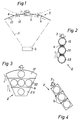
- the indicated in Fig. 1 vacuum coating system for evaporating Coating layers on optical substrates includes an evacuable via a vacuum pump known recipients (not shown).
- each substrate carrier 2 means for clamping of a substrate to be coated on both sides or for holding comprises two substrates to be coated on one side (not shown).
- the substrate supports 2 according to the invention are explained in more detail below described.
- a central evaporation source 4 is located in the lower region of the recipient indicated that in a known manner a conical vaporization jet 5th generated for vapor deposition of the surfaces held by the substrate carriers 2 Substrates.
- the substrate surfaces of the substrates to be vapor-deposited after each Twisting the substrate carrier 2 by 180 ° always in an exact angular position to the vaporization jet rising conically in the center of the recipient bring to optimal, uniform precipitation on each substrate surface can be achieved according to the invention in a radial extension of the Substrate carrier 2 at least two receiving areas for one substrate each provided between which recording areas each one, the Substrate carrier hinge or hinge 6 dividing into sections 12, 22 is located around which the substrate support sections with the substrate after both Sides freely relative to each other up to a predetermined angle are tiltable, as indicated in Fig. 1 by the dashed line.
- the Substrate carrier 2 from a dome-shaped plate, also in three Sections 12, 22 and 23 is divided by joint means 6, the middle Section 22 here means for holding three side by side Has substrates.
- the relative size of the substrates to the dome-shaped substrate carrier 2 Of course, even more substrates can be applied.
- a substrate carrier 2 according to FIG. 4 there is a strip-shaped substrate carrier 2 in three receiving areas for one each Provided substrate, between which receiving areas each hinge dividing the substrate carrier into sections 12, 22 and 23 or Hinge 6 is located around which the substrate support sections with the substrate free on both sides relative to each other up to a predetermined angle are tiltable.
- the shape of the substrate carrier is different as far as this allows, the substrate support sections with the substrate on both sides relative to each other up to one predetermined angle are freely tiltable.
Landscapes
- Chemical & Material Sciences (AREA)
- Chemical Kinetics & Catalysis (AREA)
- Engineering & Computer Science (AREA)
- Materials Engineering (AREA)
- Mechanical Engineering (AREA)
- Metallurgy (AREA)
- Organic Chemistry (AREA)
- Physical Vapour Deposition (AREA)
- Surface Treatment Of Optical Elements (AREA)
Claims (4)
- Porte-substrat pour des installations de revêtement sous vide pour vaporiser des couches de revêtement sur des faces de substrats optiques, comme des verres de lunettes en matière synthétique qui peuvent être tendus sur plusieurs de ces supports qui se trouvent dans un récipient pouvant être évacué au-dessus de sources d'évaporation échangeables, caractérisé en ce que sont prévus dans l'extension radiale du porte-substrat (2) au moins deux zones de réception pour respectivement un substrat, où se trouve entre ces zones de réception respectivement une charnière ou articulation (6) subdivisant le porte-substrat (2) en sections (12, 22), autour de laquelle les sections de porte-substrat peuvent être basculées librement avec le substrat vers les deux côtés l'une relativement à l'autre jusqu'à un angle prédéterminé.
- Porte-substrat selon la revendication 1, caractérisé par au moins deux sections (12, 22 et 23) s'étendant radialement et faisant suite à l'axe de rotation (3), qui sont constitués de parties de retenue circulaires pour les substrats et qui sont reliées par des charnières ou articulations (6) autour desquelles les sections de porte-substrat peuvent être basculées librement avec le substrat selon les deux côtés les unes relativement aux autres jusqu'à un angle prédéterminé.
- Porte-substrat selon la revendication 1, caractérisé par une plaque en forme de calotte qui est subdivisée en au moins deux sections (12, 22 et 23) par des moyens d'articulation (6) autour desquels les sections de porte-substrat peuvent être basculées librement avec le substrat vers les deux côtés les unes relativement aux autres jusqu'à un angle prédéterminé, où au moins la section médiane (22) présente des moyens pour recevoir au moins deux substrats situés l'un à côté de l'autre.
- Porte-substrat selon la revendication 1, caractérisé par un agencement en forme de bande qui est subdivisé en au moins deux zones de réception pour respectivement un substrat, où entre ces zones de réception se trouve respectivement une charnière ou articulation (6) subdivisant le porte-substrat en sections (12, 22 et 23), autour de laquelle les sections de porte-substrat peuvent être basculées librement avec le substrat vers les deux côtés les unes relativement aux autres jusqu'à un angle prédéterminé.
Applications Claiming Priority (3)
| Application Number | Priority Date | Filing Date | Title |
|---|---|---|---|
| CH120096 | 1996-05-10 | ||
| CH01200/96A CH691308A5 (de) | 1996-05-10 | 1996-05-10 | Substrat-Träger für Vakuum-Beschichtungsanlagen. |
| CH1200/96 | 1996-05-10 |
Publications (2)
| Publication Number | Publication Date |
|---|---|
| EP0806492A1 EP0806492A1 (fr) | 1997-11-12 |
| EP0806492B1 true EP0806492B1 (fr) | 2000-08-09 |
Family
ID=4204857
Family Applications (1)
| Application Number | Title | Priority Date | Filing Date |
|---|---|---|---|
| EP97107376A Expired - Lifetime EP0806492B1 (fr) | 1996-05-10 | 1997-05-05 | Porte-substrat pour dispositif de revêtement sous vide |
Country Status (6)
| Country | Link |
|---|---|
| US (1) | US6082298A (fr) |
| EP (1) | EP0806492B1 (fr) |
| JP (1) | JPH1068066A (fr) |
| CN (1) | CN1124363C (fr) |
| CH (1) | CH691308A5 (fr) |
| DE (1) | DE59702124D1 (fr) |
Families Citing this family (20)
| Publication number | Priority date | Publication date | Assignee | Title |
|---|---|---|---|---|
| FR2802947B1 (fr) * | 1999-12-28 | 2002-04-12 | St Microelectronics Sa | Support de substrats pour installation de revetement par evaporation |
| DE10261362B8 (de) * | 2002-12-30 | 2008-08-28 | Osram Opto Semiconductors Gmbh | Substrat-Halter |
| DE102004063703A1 (de) * | 2004-12-28 | 2006-07-06 | Schott Ag | Vakuumbeschichtungssystem |
| DE102005045718B4 (de) | 2005-09-24 | 2009-06-25 | Applied Materials Gmbh & Co. Kg | Träger für ein Substrat |
| CN101041889B (zh) * | 2006-03-21 | 2010-05-12 | 鸿富锦精密工业(深圳)有限公司 | 镀膜方法 |
| DE102007062618B4 (de) * | 2007-12-22 | 2009-11-05 | Carl Zeiss Vision Gmbh | Verfahren und Vorrichtung zum Beschichten von Gläsern |
| EP2093018B2 (fr) | 2008-02-25 | 2017-11-01 | Satisloh AG | Pièce de bloc pour maintenir une pièce de travail optique, en particulier un verre de lunette, pour traitement associé, et procédé de fabrication de verres de lunettes selon une prescription |
| CN101597747B (zh) * | 2008-06-05 | 2012-06-20 | 鸿富锦精密工业(深圳)有限公司 | 光学镀膜装置 |
| TWI414615B (zh) * | 2008-06-20 | 2013-11-11 | Hon Hai Prec Ind Co Ltd | 光學鍍膜裝置 |
| ATE518622T1 (de) * | 2008-06-26 | 2011-08-15 | Satisloh Ag | Verfahren zur herstellung von brillenlinsen nach rezept |
| CN102234782A (zh) * | 2010-04-26 | 2011-11-09 | 鸿富锦精密工业(深圳)有限公司 | 镀膜伞架 |
| CN101955321A (zh) * | 2010-05-21 | 2011-01-26 | 蚌埠翼诚玻璃有限公司 | 分体式镀膜架 |
| KR20120083712A (ko) * | 2011-01-18 | 2012-07-26 | 삼성엘이디 주식회사 | 서셉터 및 이를 구비하는 화학 기상 증착 장치 |
| CN103014617B (zh) * | 2011-09-22 | 2014-05-14 | 株式会社新柯隆 | 薄膜形成装置 |
| LU92190B1 (en) | 2013-05-06 | 2014-11-07 | Satisloh Gmbh | Multi part blocking piece |
| LU92191B1 (en) | 2013-05-06 | 2014-11-07 | Satisloh Gmbh | Multimaterial block piece |
| EP2963458B1 (fr) | 2014-07-05 | 2022-02-02 | Satisloh AG | Ébauche de lentille comportant un revêtement de préhension temporaire pour un procédé de verres de lunettes selon une prescription |
| JP6019310B1 (ja) * | 2015-04-16 | 2016-11-02 | ナルックス株式会社 | 蒸着装置及び蒸着装置による成膜工程を含む製造方法 |
| CN106707725B (zh) * | 2017-01-20 | 2022-07-22 | 中国电子科技集团公司第十二研究所 | 一种用于原子钟的光学透射窗 |
| EP3542956A1 (fr) | 2018-03-23 | 2019-09-25 | Carl Zeiss Vision International GmbH | Procédé de fabrication de lentilles de lunettes selon une ordonnance |
Family Cites Families (8)
| Publication number | Priority date | Publication date | Assignee | Title |
|---|---|---|---|---|
| NL7205670A (fr) * | 1972-03-16 | 1973-09-18 | ||
| US3859956A (en) * | 1974-01-10 | 1975-01-14 | Bell Telephone Labor Inc | Multiworkpiece condensation coating apparatus |
| JPS58107484A (ja) * | 1981-12-19 | 1983-06-27 | Olympus Optical Co Ltd | 薄膜形成装置における反転式蒸着装置 |
| JPS61130484A (ja) * | 1984-11-28 | 1986-06-18 | Olympus Optical Co Ltd | 真空蒸着装置の光学部品保持装置 |
| CH668430A5 (de) * | 1986-07-31 | 1988-12-30 | Satis Vacuum Ag | Vakuum-beschichtungsanlage fuer optische substrate. |
| DE3921671A1 (de) * | 1989-07-01 | 1991-01-03 | Leybold Ag | Linsenhalterung, insbesondere halterung fuer in einer hochvakuum-aufdampfanlage oder -sputteranlage zu beschichtende brillenglaslinsen |
| CH681308A5 (fr) * | 1990-05-22 | 1993-02-26 | Satis Vacuum Ag | |
| US5382345A (en) * | 1993-02-16 | 1995-01-17 | Industrial Technology Research Institute | Apparatus for simultaneously coating a film of magneto-optical recording medium on a plurality of disk substrates |
-
1996
- 1996-05-10 CH CH01200/96A patent/CH691308A5/de not_active IP Right Cessation
-
1997
- 1997-05-05 EP EP97107376A patent/EP0806492B1/fr not_active Expired - Lifetime
- 1997-05-05 DE DE59702124T patent/DE59702124D1/de not_active Expired - Lifetime
- 1997-05-07 JP JP9117151A patent/JPH1068066A/ja active Pending
- 1997-05-09 CN CN97111504.4A patent/CN1124363C/zh not_active Expired - Lifetime
- 1997-05-12 US US08/854,690 patent/US6082298A/en not_active Expired - Lifetime
Also Published As
| Publication number | Publication date |
|---|---|
| CN1170773A (zh) | 1998-01-21 |
| EP0806492A1 (fr) | 1997-11-12 |
| US6082298A (en) | 2000-07-04 |
| DE59702124D1 (de) | 2000-09-14 |
| CN1124363C (zh) | 2003-10-15 |
| JPH1068066A (ja) | 1998-03-10 |
| CH691308A5 (de) | 2001-06-29 |
Similar Documents
| Publication | Publication Date | Title |
|---|---|---|
| EP0806492B1 (fr) | Porte-substrat pour dispositif de revêtement sous vide | |
| CH668430A5 (de) | Vakuum-beschichtungsanlage fuer optische substrate. | |
| DE4115175C2 (de) | Vakuum-Beschichtungsanlage für optische Substrate | |
| DE10324928A1 (de) | Vakuumbeschichtungsanlage | |
| EP0547312A1 (fr) | Dispositif de maintien de retournement des substrats pour procédés sous vide | |
| DE2950768C2 (de) | Vorrichtung zum Aufbringen eines Sicherungsbelages aus schmelzflüssigem Kunststoff in Fleckform auf das Gewinde eines Metallschraubteiles | |
| DE3513137A1 (de) | Mehrfach-haltevorrichtung fuer zu behandelnde, z.b. zu reinigende und nachfolgend durch vakuumaufdampfen oder kathodenzerstaeubung zu beschichtende substrate | |
| EP0959147A2 (fr) | Support de lentilles | |
| DE69006870T2 (de) | Vorrichtung zum Überziehen einer ebenen Oberfläche mit einer Schicht von einheitlicher Dicke. | |
| EP0806493B1 (fr) | Appareil de dèpôt en phase vapeur pour revêtement de substrates optiques | |
| DE3874414T2 (de) | Optomechanisches analysensystem mit einem einzigen rotationspolygonspiegel. | |
| DE2337204A1 (de) | Verfahren und einrichtung zum aufdampfen mindestens einer oberflaechenschicht auf optische traeger, insbesondere glaeser | |
| EP0806491B1 (fr) | Procédé de dépôt en phase vapeur pour revêtement de substrates optiques | |
| EP0368202A1 (fr) | Procédé pour couvrir un substrat pour un écran d'affichage plan | |
| DE19918405B4 (de) | Spiegelsystem zur stereoskopischen Bildaufrichtung | |
| EP0429074A1 (fr) | Tête de fraisage à finir des piÀ¨ces, specialement pour des cylindres à impression en creux | |
| DE69004048T2 (de) | Vorrichtung zum Auftragen eines Beschichtungsmittels auf einer Substratoberfläche. | |
| EP0556480B1 (fr) | Procédé pour le revêtement de grandes surfaces courbes, particulièrement d'un écran d'une tube à rayons cathodiques, par revêtement centrifuge | |
| EP0385157A1 (fr) | Porte-substrats pour entretenir des verres à revêtir et calotte pour entretenir les porte-substrats | |
| DD292029A5 (de) | Substrathaltevorrichtung zur hartstoffbeschichtung von scheibenfoermigen, rotationssymmetrischen substraten | |
| DD200410A1 (de) | Justiervorrichtung zur herstellung sphaerischer flaechen an werkstuecken | |
| DD267263B5 (de) | Substrathaltevorrichtung zur Aufnahme und Bewegung von Substraten mit komplizierter Oberfl{chengestalt | |
| DE606821C (de) | Justiervorrichtung fuer ein Objektivpaar binokularer Mikroskope | |
| DE3838012A1 (de) | Werkstuecktraeger | |
| DE8900116U1 (de) | Werkstückträger zur Aufnahme von Brillengläsern o.dgl. beim Beschichten mit einer Flüssigkeit, insbesondere einem Hartlack |
Legal Events
| Date | Code | Title | Description |
|---|---|---|---|
| PUAI | Public reference made under article 153(3) epc to a published international application that has entered the european phase |
Free format text: ORIGINAL CODE: 0009012 |
|
| AK | Designated contracting states |
Kind code of ref document: A1 Designated state(s): DE FR GB IT |
|
| 17P | Request for examination filed |
Effective date: 19980512 |
|
| GRAG | Despatch of communication of intention to grant |
Free format text: ORIGINAL CODE: EPIDOS AGRA |
|
| 17Q | First examination report despatched |
Effective date: 19990723 |
|
| GRAG | Despatch of communication of intention to grant |
Free format text: ORIGINAL CODE: EPIDOS AGRA |
|
| GRAH | Despatch of communication of intention to grant a patent |
Free format text: ORIGINAL CODE: EPIDOS IGRA |
|
| GRAH | Despatch of communication of intention to grant a patent |
Free format text: ORIGINAL CODE: EPIDOS IGRA |
|
| GRAA | (expected) grant |
Free format text: ORIGINAL CODE: 0009210 |
|
| AK | Designated contracting states |
Kind code of ref document: B1 Designated state(s): DE FR GB IT |
|
| REF | Corresponds to: |
Ref document number: 59702124 Country of ref document: DE Date of ref document: 20000914 |
|
| GBT | Gb: translation of ep patent filed (gb section 77(6)(a)/1977) |
Effective date: 20000918 |
|
| ET | Fr: translation filed | ||
| ITF | It: translation for a ep patent filed | ||
| PLBE | No opposition filed within time limit |
Free format text: ORIGINAL CODE: 0009261 |
|
| STAA | Information on the status of an ep patent application or granted ep patent |
Free format text: STATUS: NO OPPOSITION FILED WITHIN TIME LIMIT |
|
| 26N | No opposition filed | ||
| REG | Reference to a national code |
Ref country code: GB Ref legal event code: IF02 |
|
| REG | Reference to a national code |
Ref country code: FR Ref legal event code: CD Ref country code: FR Ref legal event code: CA |
|
| REG | Reference to a national code |
Ref country code: FR Ref legal event code: PLFP Year of fee payment: 20 |
|
| PGFP | Annual fee paid to national office [announced via postgrant information from national office to epo] |
Ref country code: DE Payment date: 20160620 Year of fee payment: 20 Ref country code: GB Payment date: 20160630 Year of fee payment: 20 |
|
| PGFP | Annual fee paid to national office [announced via postgrant information from national office to epo] |
Ref country code: FR Payment date: 20160527 Year of fee payment: 20 Ref country code: IT Payment date: 20160527 Year of fee payment: 20 |
|
| REG | Reference to a national code |
Ref country code: DE Ref legal event code: R071 Ref document number: 59702124 Country of ref document: DE |
|
| REG | Reference to a national code |
Ref country code: GB Ref legal event code: PE20 Expiry date: 20170504 |
|
| PG25 | Lapsed in a contracting state [announced via postgrant information from national office to epo] |
Ref country code: GB Free format text: LAPSE BECAUSE OF EXPIRATION OF PROTECTION Effective date: 20170504 |