EP0806504A1 - Dispositif de réglage centralisé pour des pinces-fil de cantres - Google Patents
Dispositif de réglage centralisé pour des pinces-fil de cantres Download PDFInfo
- Publication number
- EP0806504A1 EP0806504A1 EP97107061A EP97107061A EP0806504A1 EP 0806504 A1 EP0806504 A1 EP 0806504A1 EP 97107061 A EP97107061 A EP 97107061A EP 97107061 A EP97107061 A EP 97107061A EP 0806504 A1 EP0806504 A1 EP 0806504A1
- Authority
- EP
- European Patent Office
- Prior art keywords
- adjusting
- adjusting rod
- thread
- rod
- adjustment device
- Prior art date
- Legal status (The legal status is an assumption and is not a legal conclusion. Google has not performed a legal analysis and makes no representation as to the accuracy of the status listed.)
- Granted
Links
- 239000011358 absorbing material Substances 0.000 claims description 2
- 238000006073 displacement reaction Methods 0.000 abstract 1
- 238000004804 winding Methods 0.000 description 23
- 230000006835 compression Effects 0.000 description 2
- 238000007906 compression Methods 0.000 description 2
- 239000000463 material Substances 0.000 description 2
- 238000005299 abrasion Methods 0.000 description 1
- 230000005540 biological transmission Effects 0.000 description 1
- 239000002184 metal Substances 0.000 description 1
- 238000000034 method Methods 0.000 description 1
- 230000007704 transition Effects 0.000 description 1
Images


Classifications
-
- D—TEXTILES; PAPER
- D02—YARNS; MECHANICAL FINISHING OF YARNS OR ROPES; WARPING OR BEAMING
- D02H—WARPING, BEAMING OR LEASING
- D02H1/00—Creels, i.e. apparatus for supplying a multiplicity of individual threads
-
- D—TEXTILES; PAPER
- D02—YARNS; MECHANICAL FINISHING OF YARNS OR ROPES; WARPING OR BEAMING
- D02H—WARPING, BEAMING OR LEASING
- D02H13/00—Details of machines of the preceding groups
- D02H13/22—Tensioning devices
- D02H13/24—Tensioning devices for individual threads
Definitions
- the invention relates to a central adjustment device for thread clamps of bobbin creels, with vertically displaceable adjusting rods, each associated with a row of bobbins, on which a control ramp is formed for each thread clamp, with which a spring-loaded bolt that controls the thread clamp in an open or in a clamping position can be adjusted and with a vertically driven adjusting lever assigned to each adjusting rod, which engages the adjusting rod and is able to move it into a first position corresponding to the open position of the thread clamp, from which the adjusting rod is adjustable into a second position corresponding to the clamping position of the thread clamp.
- a central adjustment device with the aforementioned features is known for example from DE 37 34 518. It is used for creels that have a large number of winding positions.
- Each winding unit carries a bobbin, the thread of which is drawn off overhead. The thread passes through a thread clamp and is deflected around a thread monitor needle and wound onto a winding machine by a winding machine. The winding takes place at high winding speeds, so that the air friction of the thread makes up at least a substantial part of the thread tensile force which the winding machine has to apply.
- the known central adjustment device is designed so that each gate side is assigned an electrically controlled pneumatic cylinder, which is arranged above the winding units and at the end of the gate side. Rods are articulated to the pneumatic cylinder, which are guided horizontally above the winding units. These rods are very long and consist of several sections. The horizontal rods, which are acted upon by cylinders, are connected to the adjusting levers in terms of drive. Due to the large number of components and the large lengths of conventional gates, there are correspondingly large tolerances that do not allow ideal adjustment of the central adjustment device. It is generally known to change the overall clamping forces of the thread clamps by changing the stroke of the pneumatic cylinders. However, due to the aforementioned tolerances, the consequent nonuniformity of the clamping forces cannot be compensated for. Even a uniformization of the opening of the thread clamps in their open position is not possible overall.
- thread clamps are generally known, the clamping force of which can be roughly adjusted in three stages. In this case, it is possible to influence the thread clamps individually, but because of the large number of thread clamps, a great deal of adjustment work has to be carried out, so that this setting option is ultimately not used.
- the object of the invention is to improve a central adjustment device with the features mentioned at the outset in such a way that an overall setting of all thread clamps is facilitated without having to make individual settings on all thread clamps.
- the adjusting lever engages on an adjusting part which is fastened to the adjusting rod in a vertically steplessly adjustable manner and / or in that the second position of the adjusting rod corresponding to the clamping position of the thread clamp is determined by a stop which supports it, the vertical position of which is stepless until adjustable to support the bolt on the control ramp.
- the vertically driven adjusting lever is influenced as a whole.
- the adjusting part is provided, through the stepless vertical adjustment of which it can be achieved that the adjusting rod is positioned higher or lower.
- all inclined surfaces of an actuating rod are positioned higher or lower, so that all positions of the thread clamp are influenced insofar as they can be influenced by these inclined surfaces.
- the result is an adjustability in rows of coils, by means of which all tolerances of the central adjustment device between this adjusting part and a pneumatic cylinder as an example drive element can be switched off. Due to the stepless vertical adjustment between the adjusting part and the adjusting rod, the vertical stroke of the adjusting rod can be changed so that the free passage of the thread between a jaw of the thread clamp and an abutment of this jaw is kept adjustable the same.
- the central adjustment device can be designed in such a way that the second position of the actuating rod, which corresponds to the clamping position of the thread clamp, is determined by a stop supporting it, the vertical position of which can be adjusted continuously until the bolt is supported on the control ramp. Due to the adjustability of the In the vertical position of the supporting stop, the adjusting rod has an adjustment option that is independent of the adjustment option via the adjustment part. The adjusting rod can thus be continuously adjusted with regard to the clamping positions of its thread clamps, regardless of how the open position was set via the setting part. Through the infinitely variable adjustment of the stop, if necessary, into the area in which the bolt is supported on the control ramp, an exact material-related clamping force can be set.
- the central adjustment device such that the adjustment part is arranged between the upper end of the adjustment rod and the adjustment lever.
- the result is a compact design at the upper end of the adjusting rod with regard to the rods and adjusting levers driven by the pneumatic cylinder.
- the adjusting part and the adjusting rod are screwed together in a structurally simple manner.
- the screw connection can be easily loosened in order to bring the adjusting rod to the adjustment part in a relatively different position.
- the central adjustment device can be designed so that the adjusting part and / or the adjusting rod have elongated holes, the length of which corresponds to the vertical adjustment range.
- the central adjustment device can be formed so that the adjusting part lies loosely on the vertically driven adjusting lever, which can be removed from the vertical range of movement of the adjusting rod and can lift the adjusting rod from its second position into the first.
- the slack between the adjusting part and the vertically driven adjusting lever makes it possible to position the adjusting rod including the adjusting part for the clamping position of the thread clamp.
- the drive of the adjusting lever is designed so that the adjusting rod can be lifted from this position with the adjusting lever while eliminating the slack.
- the central adjustment device can be designed in such a way that the vertically driven adjustment lever is able to release the adjustment part, as a result of which the adjusting rod, due to its own weight, reaches its second position, which corresponds to the clamping position of the thread clamp. As a result, it is not necessary to provide a drive for the adjusting rod with which it arrives in the position corresponding to the clamping position of the thread clamp.
- the actuating lever which drives the actuating rod or its adjusting part has to transmit a corresponding actuating force which is usually exerted by a pneumatic cylinder as the usual drive part of the central adjusting device.
- the transmission of the actuating force takes place horizontally above the winding units, so that a deflection of movement from the horizontal into the vertical is necessary.
- the central adjustment device is therefore designed such that the vertically driven adjusting lever is a two-armed pivoting lever, one arm of which can be acted upon by a drive and the adjusting part rests loosely on the other arm.
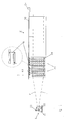
- the coil creel 10 shown in FIGS. 1, 2 is a so-called V-creel, from the two creel sides 10 'of which threads F run towards a winding device, namely a warping machine 11, from which the group of threads of threads F is wound onto a winding tree 21.
- the winding tree 21 has winding disks 21 ', between which a pressure roller 22 presses on the winding which is constantly increasing in diameter during winding.
- the winding process is controlled by a control panel 23 of the winding device, from where it can also be switched off if a thread F is broken.
- the coil gate 10 has a larger number of gate fields 20, in which coils 24 are arranged in rows and columns in a conventional manner.
- FIG. 2 schematically shows rotary gates 25 illustrated with dash-dotted rotating circles, which can be equipped from the interior 26 of the bobbin gate 10, while the threads F are drawn off on the outer sides of the gate sides 10 '.
- each thread guide device has a thread clamp 14 which is attached to a gate strut 26 in a manner not shown.
- the gate strut 26 is a component of the gate frame, which is not shown in any more detail, from the coil mandrels of which the coils 24 are also carried.
- the thread clamp 14 has a tubular housing 27 with an external abutment 29. This interacts with a clamping jaw 30 which is adjustable in the plane of the illustration. Between the jaw 30 and the abutment 29, the thread F runs perpendicular to the plane of representation. The thread course is ideally such that the thread does not touch either the jaw 30 or the abutment 29.
- Such a guiding of the thread provides, for example, pre-wrapping rods arranged in the space between the thread clamp 14 and the associated bobbin, which are known per se and are therefore not shown here.
- the jaw 30 is held by a bolt 31 which is guided in the housing 27 such that the jaw 30 can only move in accordance with this guide.
- the bolt 31 is guided in the bores shown in FIGS. 3, 4 in the directions of its longitudinal axis.
- the jaw-side end 40 of the bolt 31 has a guide pin 41 which is vertical to the plane of the illustration and whose two ends are guided in slots 42 which are located in retaining lugs 43 of the jaw 30 parallel to the bolt.
- the bottom 44 of the jaw has a hole which is penetrated by the bolt 31 so that it is always arranged perpendicular to the bolt 31.
- a compression spring 45 is supported, which tries to press the jaw 30 into its clamping position.
- a compression spring 47 is provided which is supported at one end on the housing 27 and at the other end on the collar 48 of the bolt 31, so that it tries to press the clamping jaw 30 into the clamping position.
- control ramp 49 is a sheet metal part fastened to an adjusting rod 50. If this is in the high position shown in FIG. 3, the bolt 31 is displaced to the right against the force of the spring 47. The stroke to be achieved by the control ramp 49 is so large that the full passage gap between the clamping jaw 30 and the abutment 29 is released. This can already be the case be when the bolt 31 has not yet reached the position shown in Figure 3, but is still supported on the control ramp 49. If, on the other hand, the actuating rod 50 is in its low position according to FIG. 4, the spring 47 is able to move the bolt 31 to the left against the action of the spring 45, so that the clamp 14 closes.
- the adjusting rod 50 is held up by an adjusting lever 51, which is designed as a two-armed angle lever. It is driven by a rod 52 which is articulated on the angle arm 53 and is adjusted horizontally, for example as a result of being acted upon by a pneumatic cylinder 54 which acts on the lever arm 53 via the rod 52.
- a pivoting about the pivot point fixed to the frame frame 55 in a counterclockwise direction causes the lever arm 56 to lower and thus the transition of the adjusting rod 50 from the position shown in FIG. 3 to the low position shown in FIG.
- the adjusting lever 51 is quickly folded away so that the rod 50 falls down. Your case is limited by a stop 57 which is adjustably fastened to the gate strut 26 and which is made of sound-absorbing material.
- the stop 57 is provided with an elongated hole 59 so that it can be adjusted up and down in the circumference of this elongated hole.
- the stop 57 is adjusted completely downward, for example, when the bolt 31 is still supported in a manner not shown in the inclined area of the control ramp 49 and it is to be ensured that the thread clamp 14 clamps with full force of the spring 45.
- a position of the actuating rod 50 is set with the stop 57, in which the bolt 31 is supported on the slope of the control ramp 49. With that a exact material-related clamping force can be set continuously.
- the setting is made in that part of the control ramp 49 with respect to which the bolt 31 is freely movable within the slot 42 without the thread clamp 14 opening.
- the adjusting rod 50 is provided with an adjusting part 60, namely with an angle, the one angle leg 60 'of which is arranged approximately horizontally and lies loosely on a support pin 61 of the angle arm 56 of the adjusting lever 51.
- the other angle arm 60 ′′ is fastened to the upper end 50 ′ of the adjusting rod 50 and is provided with an elongated hole 62 so that it can be adjusted vertically.
- the upper end 50 'of the actuating rod 50 is attached as far as possible upwards to the angle arm 60'. This is advisable, for example, if the full open position of the thread clamp 14 shown in FIG. 3 is to be reached, but the bolt 31 is still supported on the inclined surface of the control ramp 49 in a manner not shown.
Landscapes
- Engineering & Computer Science (AREA)
- Textile Engineering (AREA)
- Warping, Beaming, Or Leasing (AREA)
- Moulding By Coating Moulds (AREA)
- Particle Accelerators (AREA)
- Unwinding Of Filamentary Materials (AREA)
Applications Claiming Priority (2)
| Application Number | Priority Date | Filing Date | Title |
|---|---|---|---|
| DE29608167U | 1996-05-06 | ||
| DE29608167U DE29608167U1 (de) | 1996-05-06 | 1996-05-06 | Zentralverstelleinrichtung für Fadenklemmen von Spulengattern |
Publications (2)
| Publication Number | Publication Date |
|---|---|
| EP0806504A1 true EP0806504A1 (fr) | 1997-11-12 |
| EP0806504B1 EP0806504B1 (fr) | 2000-11-02 |
Family
ID=8023583
Family Applications (1)
| Application Number | Title | Priority Date | Filing Date |
|---|---|---|---|
| EP97107061A Expired - Lifetime EP0806504B1 (fr) | 1996-05-06 | 1997-04-29 | Dispositif de réglage centralisé pour des pinces-fil de cantres |
Country Status (3)
| Country | Link |
|---|---|
| EP (1) | EP0806504B1 (fr) |
| DE (2) | DE29608167U1 (fr) |
| ES (1) | ES2151203T3 (fr) |
Families Citing this family (9)
| Publication number | Priority date | Publication date | Assignee | Title |
|---|---|---|---|---|
| US7086111B2 (en) | 2001-03-16 | 2006-08-08 | Braun Gmbh | Electric dental cleaning device |
| DK1367958T3 (da) | 2001-03-14 | 2008-01-28 | Braun Gmbh | Anordning til tandrensning |
| DE10159395B4 (de) | 2001-12-04 | 2010-11-11 | Braun Gmbh | Vorrichtung zur Zahnreinigung |
| US8443476B2 (en) | 2001-12-04 | 2013-05-21 | Braun Gmbh | Dental cleaning device |
| DE102004062150A1 (de) | 2004-12-23 | 2006-07-13 | Braun Gmbh | Auswechselbares Zubehörteil für ein Elektrokleingerät und Verfahren zum Bestimmen der Benutzungsdauer des Zubehörteils |
| EP2420203B1 (fr) | 2010-08-19 | 2019-10-23 | Braun GmbH | Unité de moteur à résonance et dispositif électrique avec unité de moteur à résonance |
| EP2550937B1 (fr) | 2011-07-25 | 2014-02-26 | Braun GmbH | Connexion magnétique entre la manche d'une brosse à dents et la tête de brosse |
| CN103703668B (zh) | 2011-07-25 | 2016-12-07 | 博朗有限公司 | 线性电动聚合物马达和具有所述线性电动聚合物马达的装置 |
| EP2550938B1 (fr) | 2011-07-25 | 2015-01-14 | Braun GmbH | Dispositif d'hygiène buccale |
Citations (7)
| Publication number | Priority date | Publication date | Assignee | Title |
|---|---|---|---|---|
| EP0012235A1 (fr) * | 1978-12-13 | 1980-06-25 | Hacoba Textilmaschinen GmbH & Co KG | Dispositif et procédé pour ourdir des fils |
| US4598184A (en) * | 1985-04-16 | 1986-07-01 | West Point Foundry And Machine Co. | Thread tension monitoring and clamping apparatus |
| US4664335A (en) * | 1984-10-06 | 1987-05-12 | Hacoba Textilmaschinen Gmbh & Co. Kg | Creel for warping machine |
| US4819310A (en) * | 1986-04-02 | 1989-04-11 | Benninger Ag | Apparatus for regulating the warp section tension during warping |
| DE3734518A1 (de) * | 1987-10-13 | 1989-04-27 | Hacoba Textilmaschinen | Vorrichtung fuer die anlaufsteuerung von spulengattern |
| EP0319477A1 (fr) * | 1987-12-03 | 1989-06-07 | Benninger AG | Dispositif pour compenser la tension du fil dans un cantre de bobine |
| EP0511160A1 (fr) * | 1991-04-24 | 1992-10-28 | Benninger AG | Dispositif de contrôle de la course du fil sur un cantre |
-
1996
- 1996-05-06 DE DE29608167U patent/DE29608167U1/de not_active Expired - Lifetime
-
1997
- 1997-04-29 EP EP97107061A patent/EP0806504B1/fr not_active Expired - Lifetime
- 1997-04-29 ES ES97107061T patent/ES2151203T3/es not_active Expired - Lifetime
- 1997-04-29 DE DE59702550T patent/DE59702550D1/de not_active Expired - Fee Related
Patent Citations (7)
| Publication number | Priority date | Publication date | Assignee | Title |
|---|---|---|---|---|
| EP0012235A1 (fr) * | 1978-12-13 | 1980-06-25 | Hacoba Textilmaschinen GmbH & Co KG | Dispositif et procédé pour ourdir des fils |
| US4664335A (en) * | 1984-10-06 | 1987-05-12 | Hacoba Textilmaschinen Gmbh & Co. Kg | Creel for warping machine |
| US4598184A (en) * | 1985-04-16 | 1986-07-01 | West Point Foundry And Machine Co. | Thread tension monitoring and clamping apparatus |
| US4819310A (en) * | 1986-04-02 | 1989-04-11 | Benninger Ag | Apparatus for regulating the warp section tension during warping |
| DE3734518A1 (de) * | 1987-10-13 | 1989-04-27 | Hacoba Textilmaschinen | Vorrichtung fuer die anlaufsteuerung von spulengattern |
| EP0319477A1 (fr) * | 1987-12-03 | 1989-06-07 | Benninger AG | Dispositif pour compenser la tension du fil dans un cantre de bobine |
| EP0511160A1 (fr) * | 1991-04-24 | 1992-10-28 | Benninger AG | Dispositif de contrôle de la course du fil sur un cantre |
Also Published As
| Publication number | Publication date |
|---|---|
| EP0806504B1 (fr) | 2000-11-02 |
| ES2151203T3 (es) | 2000-12-16 |
| DE29608167U1 (de) | 1997-09-18 |
| DE59702550D1 (de) | 2000-12-07 |
Similar Documents
| Publication | Publication Date | Title |
|---|---|---|
| DE102010005720B3 (de) | Haspel zur Aufnahme eines Coils aus Draht oder einem rohrförmigen oder einem bandförmigen Material zur Abgabe an eine nachgeschaltete Verarbeitungsmaschine | |
| EP0546150B1 (fr) | Dispositif de bobinage muni d'une unite de commande pour la regulation de la pression d'appui d'une bobine sur un cylindre entraineur | |
| DE4114012A1 (de) | Kettenwirkmaschine mit auf einer legebarre angebrachten individuell bewegbaren fadenfuehrer | |
| DE4303967A1 (de) | Kettenwirkmaschine mit auf einer Legebarre angebrachten individuell bewegbaren Fadenführern | |
| EP0806504B1 (fr) | Dispositif de réglage centralisé pour des pinces-fil de cantres | |
| CH615964A5 (fr) | ||
| DE3505913C2 (fr) | ||
| DE1919533B2 (de) | Fadenwechselvorrichtung für Rundstrickmaschinen | |
| DE2757679C2 (de) | Fadenkreuzvorrichtung für Schärmaschinen | |
| DE4115059C2 (de) | Vorrichtung zum Begrenzen der Fadenballons an einem Spulengatter | |
| DE3327633C2 (de) | Fadenbremsvorrichtung | |
| DE2534364C2 (fr) | ||
| DE3033102A1 (de) | Doppelzylinder-strickmaschine | |
| EP0511160B1 (fr) | Dispositif de contrôle de la course du fil sur un cantre | |
| DE19703002C2 (de) | Vorrichtung zum Schären einer Fadenschar auf einem Kettbaum | |
| EP0012937A1 (fr) | Dispositif de va-et-vient pour bobinoir avec amplitude variable et ajustement collectif et régulier de l'angle des flancs des paquets de fil | |
| EP0529429B1 (fr) | Frein à disques pour fils textiles | |
| EP2122024A1 (fr) | Dispositif de positionnement des fils à l'intérieur de la largeur de bande d'une section d'ourdissage et procédé d'ourdissage | |
| DE3123282C1 (de) | Vorrichtung zur Aufnahme eines Fadens von einer Spule und UEbergabe an ein Arbeitsorgan | |
| DD208634A5 (de) | Vorrichtung zur aufnahme eines streckrollenaggregates | |
| DE19525434C2 (de) | Faden-bzw. Garnklemmung | |
| EP0441178A1 (fr) | Banc à étirer à courroies et continu à filer avec une pluralité de telles bancs à étirer à courroies | |
| DE2735760A1 (de) | Vorrichtung zum abnehmen von faeden, insbesondere von garnen | |
| DE29608169U1 (de) | Wickelvorrichtung für Fäden von Spulengattern | |
| DE3137346A1 (de) | Spinnereimaschine mit streckwerken |
Legal Events
| Date | Code | Title | Description |
|---|---|---|---|
| PUAI | Public reference made under article 153(3) epc to a published international application that has entered the european phase |
Free format text: ORIGINAL CODE: 0009012 |
|
| AK | Designated contracting states |
Kind code of ref document: A1 Designated state(s): CH DE ES IT LI |
|
| 17P | Request for examination filed |
Effective date: 19971111 |
|
| GRAG | Despatch of communication of intention to grant |
Free format text: ORIGINAL CODE: EPIDOS AGRA |
|
| 17Q | First examination report despatched |
Effective date: 20000131 |
|
| GRAG | Despatch of communication of intention to grant |
Free format text: ORIGINAL CODE: EPIDOS AGRA |
|
| GRAH | Despatch of communication of intention to grant a patent |
Free format text: ORIGINAL CODE: EPIDOS IGRA |
|
| GRAH | Despatch of communication of intention to grant a patent |
Free format text: ORIGINAL CODE: EPIDOS IGRA |
|
| GRAA | (expected) grant |
Free format text: ORIGINAL CODE: 0009210 |
|
| AK | Designated contracting states |
Kind code of ref document: B1 Designated state(s): CH DE ES IT LI |
|
| REG | Reference to a national code |
Ref country code: CH Ref legal event code: NV Representative=s name: E. BLUM & CO. PATENTANWAELTE Ref country code: CH Ref legal event code: EP |
|
| REF | Corresponds to: |
Ref document number: 59702550 Country of ref document: DE Date of ref document: 20001207 |
|
| REG | Reference to a national code |
Ref country code: ES Ref legal event code: FG2A Ref document number: 2151203 Country of ref document: ES Kind code of ref document: T3 |
|
| ITF | It: translation for a ep patent filed | ||
| EN | Fr: translation not filed | ||
| PG25 | Lapsed in a contracting state [announced via postgrant information from national office to epo] |
Ref country code: ES Free format text: LAPSE BECAUSE OF NON-PAYMENT OF DUE FEES Effective date: 20010430 |
|
| PG25 | Lapsed in a contracting state [announced via postgrant information from national office to epo] |
Ref country code: LI Free format text: LAPSE BECAUSE OF NON-PAYMENT OF DUE FEES Effective date: 20010528 Ref country code: CH Free format text: LAPSE BECAUSE OF NON-PAYMENT OF DUE FEES Effective date: 20010528 |
|
| PLBE | No opposition filed within time limit |
Free format text: ORIGINAL CODE: 0009261 |
|
| STAA | Information on the status of an ep patent application or granted ep patent |
Free format text: STATUS: NO OPPOSITION FILED WITHIN TIME LIMIT |
|
| 26N | No opposition filed | ||
| REG | Reference to a national code |
Ref country code: CH Ref legal event code: PL |
|
| REG | Reference to a national code |
Ref country code: ES Ref legal event code: FD2A Effective date: 20020514 |
|
| PG25 | Lapsed in a contracting state [announced via postgrant information from national office to epo] |
Ref country code: IT Free format text: LAPSE BECAUSE OF NON-PAYMENT OF DUE FEES;WARNING: LAPSES OF ITALIAN PATENTS WITH EFFECTIVE DATE BEFORE 2007 MAY HAVE OCCURRED AT ANY TIME BEFORE 2007. THE CORRECT EFFECTIVE DATE MAY BE DIFFERENT FROM THE ONE RECORDED. Effective date: 20050429 |
|
| PGFP | Annual fee paid to national office [announced via postgrant information from national office to epo] |
Ref country code: DE Payment date: 20090421 Year of fee payment: 13 |
|
| PG25 | Lapsed in a contracting state [announced via postgrant information from national office to epo] |
Ref country code: DE Free format text: LAPSE BECAUSE OF NON-PAYMENT OF DUE FEES Effective date: 20101103 |