EP0806518B1 - Dispositif pour le pétrissage d'une pulpe à consistance élevée - Google Patents
Dispositif pour le pétrissage d'une pulpe à consistance élevée Download PDFInfo
- Publication number
- EP0806518B1 EP0806518B1 EP97104827A EP97104827A EP0806518B1 EP 0806518 B1 EP0806518 B1 EP 0806518B1 EP 97104827 A EP97104827 A EP 97104827A EP 97104827 A EP97104827 A EP 97104827A EP 0806518 B1 EP0806518 B1 EP 0806518B1
- Authority
- EP
- European Patent Office
- Prior art keywords
- teeth
- kneading
- pulp
- angle
- kneading device
- Prior art date
- Legal status (The legal status is an assumption and is not a legal conclusion. Google has not performed a legal analysis and makes no representation as to the accuracy of the status listed.)
- Expired - Lifetime
Links
- 238000004898 kneading Methods 0.000 title claims abstract description 40
- 239000011800 void material Substances 0.000 claims 1
- 239000000835 fiber Substances 0.000 abstract description 7
- 239000002657 fibrous material Substances 0.000 description 7
- 239000000463 material Substances 0.000 description 7
- 230000000694 effects Effects 0.000 description 6
- 239000000126 substance Substances 0.000 description 6
- 230000008859 change Effects 0.000 description 4
- 230000006835 compression Effects 0.000 description 3
- 238000007906 compression Methods 0.000 description 3
- 238000000034 method Methods 0.000 description 3
- 239000010893 paper waste Substances 0.000 description 3
- 230000008569 process Effects 0.000 description 3
- 239000004744 fabric Substances 0.000 description 2
- 238000003754 machining Methods 0.000 description 2
- 230000004888 barrier function Effects 0.000 description 1
- 229920002678 cellulose Polymers 0.000 description 1
- 239000001913 cellulose Substances 0.000 description 1
- 239000000356 contaminant Substances 0.000 description 1
- 210000004013 groin Anatomy 0.000 description 1
- 235000011837 pasties Nutrition 0.000 description 1
- 230000001737 promoting effect Effects 0.000 description 1
- 239000007858 starting material Substances 0.000 description 1
- 239000000725 suspension Substances 0.000 description 1
- 238000011144 upstream manufacturing Methods 0.000 description 1
- 239000002023 wood Substances 0.000 description 1
Images
Classifications
-
- D—TEXTILES; PAPER
- D21—PAPER-MAKING; PRODUCTION OF CELLULOSE
- D21B—FIBROUS RAW MATERIALS OR THEIR MECHANICAL TREATMENT
- D21B1/00—Fibrous raw materials or their mechanical treatment
- D21B1/04—Fibrous raw materials or their mechanical treatment by dividing raw materials into small particles, e.g. fibres
- D21B1/12—Fibrous raw materials or their mechanical treatment by dividing raw materials into small particles, e.g. fibres by wet methods, by the use of steam
- D21B1/30—Defibrating by other means
- D21B1/34—Kneading or mixing; Pulpers
- D21B1/342—Mixing apparatus
Definitions
- the invention relates to a device for kneading highly consistent fibrous material according to the preamble of claim 1.
- a kneading device is e.g. B. known from DE-42 37 433 A1.
- This for kneading Device suitable for waste paper serves to intensively mechanically and possibly the substance can also be processed thermally, thereby removing the contaminants contained in the fibers can be detached, crushed and / or brought below the visibility limit.
- the starting material intended for the kneading process already has a pasty or soft-crumbly shape, so is no longer with wood chips or still coarser substances comparable. Other than z. B.
- the pulp in pulp refiners in such machines the pulp is not in a pumpable suspension edited, but just as a high consistency substance, preferably with one Dry content between 15 and 40%. In this way, considerable Transfer shear forces into the fiber material, whereby the stated goals can be achieved, without any significant change in fiber length.
- the effect of mechanical treatment is further enhanced by heat, e.g. by setting a fiber temperature of 90 ° Celsius or even higher.
- the substance In the kneader, the substance usually stays in for 15 seconds to several minutes the processing rooms and is due to the distance of more than 3 mm between the tools are mainly processed by fiber-fiber friction. As is known this protects the fiber and the processing tools become slow worn.
- the basic structure of the kneader is almost always as in the example of DE-42 37 433 A1 recognizable:
- the rotor is essentially cylindrical, and the material becomes conveyed axially between standing and moving kneading teeth.
- Such kneaders have long proven themselves especially for the use of waste paper.
- the transportation of the Material through the processing zone is usually both by tilting the Machining teeth and secured by a suitable conveyor, which e.g. is designed as a helix on the kneader shaft.
- the funding parameters are so practically firm.
- the invention is therefore based on the object of a device for kneading to create highly consistent fibrous material, which without any significant additional effort Possibility to change the transport movement in the processing zone.
- the front of the teeth of such a kneading tool moves relative to the Pulp too. Since the incline on the front is a sliding and Deflection movement of the substance to be transported in the transport direction causes the mass transfer is supported in the kneader. Prerequisite for this is the relative movement between the bevel and the pulp, either by doing so can arise that the tooth in question belongs to the moving kneading tool or in that a fixed tooth of a material moved in the circumferential direction is flowed to.
- the device equipped according to the invention now exists the possibility of simply turning a tooth or a group of teeth one or more kneading tools the surface of the previously used as the back To bring tooth to the front.
- the transport effect of the angle depends on the incline in relation to the direction of movement of the tooth or the material on the unmoved tooth, can be turned by turning such a tooth, e.g. by 180 ° with different angles of the slopes also a different one Transport effect can be achieved.
- the mass transfer in the kneader can be used for various applications and the same kneader are desired differently.
- a part of or all accordingly equipped teeth are turned. Even in the cases where the Slopes on the front and back are the same, can be turned one less worn area for transporting the fabric.
- the slope can even be chosen so that the Material transport brakes.
- an upstream or downstream one would Transport device can still be forced throughput through the machine have to.
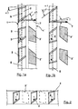
- Figure 1a shows in a developed form the supervision of the part of a movable Kneading tool 1, which belongs to a kneader with an axial flow of material.
- a movable Kneading tool which belongs to a kneader with an axial flow of material.
- Cut teeth are indicated 2 ' a fixed kneading tool.
- the teeth 2, 2 ' are both on the front as well also bevelled on the back.
- everyone has Teeth are essentially the same shape, but this does not always have to be the case (see also Fig. 3). Due to their arrangement in the kneading device, the teeth 2 at Operation moved in the circumferential direction (arrow 3).
- a plane E is spanned here, shown in section.
- the The direction of transport T of the fibrous material is perpendicular to this plane E.
- the angles which have the bevels in relation to the transport direction T are at an angle ⁇ 1 Front and angle ⁇ 2 on the back - each in the position before turning of the tooth - specified.
- Fig. 1 b shows the parts of Fig. 1 a after turning the teeth 2 and 2 'through 180 °.
- the transport effect on the front of the teeth is because of the lower Inclination less. Of course, these tooth surfaces can also be curved.
- the decisive factor is their transport effect.
- Figure 2 shows a slightly different attachment of the device to the invention belonging teeth 2.
- the turning of the teeth can be done Turn this bar 4 done.
- Such a bar can be used as a rotor or stator belong on which it is attached along its length substantially axially aligned.
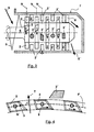
- Figure 3 shows in section an axially constructed kneading device, in which the Transport movement of the fibrous material also takes place axially again.
- the presentation is rough schematic and contains e.g. only a small part of the real teeth.
- the Fibrous material S is fed into the actual feed screw 5 Machining zone pressed.
- there the teeth 2 'belonging to the stator housing 7 are shown cut.
- a part of here they have a varied, strongly rounded shape, but another part is cubic without bevels.
- Fig. 4 shows the part of a kneading tool that belongs to a radial kneader.
- the Mass transport with transport direction T thus takes place radially outwards from the inside.
- the circumferential movement (arrow 3) of the tooth base normal N 'of the teeth 2 becomes one cylindrical surface F spanned.
- the holes 9 are provided for fastening screws.
- the one to the stator belonging tooth 2 ' is only indicated. Unlike the example shown here, it can differ in shape from the moving teeth 2.
Landscapes
- Engineering & Computer Science (AREA)
- Life Sciences & Earth Sciences (AREA)
- Wood Science & Technology (AREA)
- Mechanical Engineering (AREA)
- Spinning Methods And Devices For Manufacturing Artificial Fibers (AREA)
- Mixers Of The Rotary Stirring Type (AREA)
- Processing And Handling Of Plastics And Other Materials For Molding In General (AREA)
- Preparation Of Clay, And Manufacture Of Mixtures Containing Clay Or Cement (AREA)
- Paper (AREA)
Claims (10)
- Dispositif de pétrissage d'une matière fibreuse (S) très consistante, comportant au moins deux outils de pétrissage (1, 1') coaxiaux, déplaçables l'un par rapport à l'autre et présentant sensiblement une symétrie de révolution, qui présentent des dents (2, 2') disposées en rangées annulaires, entre lesquelles se trouvent des entredents, dans lequel des espaces vides annulaires se trouvent entre les rangées de dents et sont positionnés les uns par rapport aux autres, de manière qu'au moins une rangée de dents d'un outil de pétrissage (1, 1') pénètre à l'intérieur d'un espace vide annulaire d'un autre outil de pétrissage (1', 1), dans lequel au moins sur une partie des dents (2, 2') la face avant présente une surface oblique sur laquelle la matière fibreuse est déviée dans le sens (T) du transport, par mouvement relatif entre la matière fibreuse et la surface qui forme la face avant, dans lequel le sens (T) du transport résulte du passage de la matière fibreuse à travers le dispositif de pétrissage, caractérisé en ce qu'au moins une partie des dents (2, 2') contient également des surfaces obliques sur la face arrière, en ce que l'angle (α1) de la surface oblique de la face avant diffère d'au moins 5 degrés de l'angle (α2) de la face arrière, et en ce qu'au moins une partie des dents (2, 2') est fixée de manière non permanente de façon que la position de la face avant et de la face arrière soit interchangeable par retournement des dents (2, 2').
- Dispositif de pétrissage selon la revendication 1, caractérisé en ce que le retournement de la dent (2, 2') s'effectue sous un angle de 180 degrés.
- Dispositif de pétrissage selon la revendication 1, ou 2, caractérisé en ce que l'angle (α1) de la surface oblique de la face avant diffère d'au moins 15 degrés de l'angle (α2) de la face arrière.
- Dispositif de pétrissage selon la revendication 1, 2 ou 3, caractérisé en ce que le sens (T) de transport de la matière fibreuse est perpendiculaire à la surface (E, F) définie par le mouvement des dents.
- Dispositif de pétrissage selon la revendication 4, caractérisé en ce que le sens (T) de transport se situe dans la direction de l'axe des outils de pétrissage.
- Dispositif de pétrissage selon la revendication 4, caractérisé en ce que le sens (T) de transport est radial et son centre se situe dans l'axe médian des outils de pétrissage (1, 1').
- Dispositif de pétrissage selon l'une des revendications précédentes, caractérisé en ce que plusieurs dents (2, 2') d'un outil de pétrissage (1, 1') sont réunies sur un segment de garniture qui peut être retourné.
- Dispositif de pétrissage selon les revendications 6 et 7, caractérisé en ce que le segment de garniture contient un anneau fermé.
- Dispositif de pétrissage selon la revendication 8, caractérisé en ce que le segment de garniture contient un segment annulaire qui s'étend sur un angle périphérique de 180 degrés au plus.
- Dispositif de pétrissage selon les revendications 6 et 7, caractérisé en ce que le segment de garniture contient des baguettes (4) qui sont fixées axialement sur l'outil de pétrissage (1, 1') et qui portent chacune des dents (2) faisant partie de plusieurs rangées de dents.
Applications Claiming Priority (2)
| Application Number | Priority Date | Filing Date | Title |
|---|---|---|---|
| DE19618886 | 1996-05-10 | ||
| DE19618886 | 1996-05-10 |
Publications (2)
| Publication Number | Publication Date |
|---|---|
| EP0806518A1 EP0806518A1 (fr) | 1997-11-12 |
| EP0806518B1 true EP0806518B1 (fr) | 2001-06-27 |
Family
ID=7793965
Family Applications (1)
| Application Number | Title | Priority Date | Filing Date |
|---|---|---|---|
| EP97104827A Expired - Lifetime EP0806518B1 (fr) | 1996-05-10 | 1997-03-21 | Dispositif pour le pétrissage d'une pulpe à consistance élevée |
Country Status (5)
| Country | Link |
|---|---|
| US (1) | US5836689A (fr) |
| EP (1) | EP0806518B1 (fr) |
| AT (1) | ATE202603T1 (fr) |
| DE (1) | DE59703888D1 (fr) |
| NO (1) | NO310307B1 (fr) |
Families Citing this family (7)
| Publication number | Priority date | Publication date | Assignee | Title |
|---|---|---|---|---|
| US6267847B1 (en) * | 1999-11-15 | 2001-07-31 | Voith Sulzer Paper Technology North America, Inc. | Pulper for a stock preparation system |
| DE10024122A1 (de) * | 2000-05-18 | 2001-11-22 | Lipp Mischtechnik Gmbh | Vorrichtung zur Herstellung von Kaugummi |
| AU2001213042A1 (en) * | 2000-11-13 | 2002-05-21 | Morinaga And Co. Ltd. | Kneading device and forming device |
| US6767123B2 (en) * | 2001-08-15 | 2004-07-27 | Morinaga & Co., Ltd. | Kneading device |
| CN101725065B (zh) * | 2009-12-01 | 2011-09-07 | 沈阳市宏芮化学品厂 | 一种反刍式高浓碎浆机 |
| SE536456C2 (sv) * | 2011-12-15 | 2013-11-12 | Metso Paper Sweden Ab | Blandningsenhet innefattande åtminstone två rotorkroppar föranvändning i en blandningsanordning och en blandningsanordning |
| DE102021119250B3 (de) * | 2021-07-26 | 2022-07-28 | Voith Patent Gmbh | Vorrichtung zum Auflösen von Faserstoff |
Family Cites Families (16)
| Publication number | Priority date | Publication date | Assignee | Title |
|---|---|---|---|---|
| DE446025C (de) * | 1926-08-21 | 1927-06-22 | Eduard Sterzl | Verfahren und Vorrichtung zur Zerkleinerung, Vermahlung, Auffaserung, Mischung oder Verfilzung von feuchten oder trockenen Stoffen |
| US1711154A (en) * | 1926-12-30 | 1929-04-30 | Turbinator Company Inc | Mixing and grinding device |
| US1977955A (en) * | 1930-04-02 | 1934-10-23 | Lancaster Asphalt Inc | Mixing and reducing apparatus |
| US2283008A (en) * | 1940-08-01 | 1942-05-12 | Pennsylvania Salt Mfg Co | Chemical processing apparatus |
| US2520424A (en) * | 1947-05-02 | 1950-08-29 | Procter & Gamble | Continuous hydrogenator |
| CH278575A (de) * | 1949-11-04 | 1951-10-31 | List Heinz | Misch- und Knetmaschine. |
| BE561975A (fr) * | 1956-11-14 | |||
| NL136122C (fr) * | 1960-08-22 | 1900-01-01 | ||
| US3938783A (en) * | 1970-10-30 | 1976-02-17 | The Upjohn Company | Method for continuous mixing of foam materials |
| GB1390190A (en) * | 1971-07-01 | 1975-04-09 | Wisz E | Mixing apparatus and method |
| JPS59167240A (ja) * | 1983-03-14 | 1984-09-20 | Chisso Corp | 有機フイラ−を配合された熱可塑性樹脂組成物の成形物の製法及びそのための装置 |
| EP0303728B1 (fr) * | 1987-08-21 | 1991-09-11 | Schumacher, Walter Dr. Ing. | Dispositif pour extruder, expanser et/ou traiter thermiquement des matières ou des mélanges de matières |
| US5032073A (en) * | 1989-10-06 | 1991-07-16 | Thermax Wire Corp. | Thin walled high velocity propagation of foamed thermoplastic resins |
| DE4118091A1 (de) * | 1991-06-03 | 1992-12-10 | Theysohn Friedrich Fa | Vorrichtung zum plastifizieren von kunststoff |
| DE4237433C2 (de) * | 1992-11-06 | 1994-05-11 | Voith Gmbh J M | Stoffknetmaschine |
| US5450368A (en) * | 1993-12-28 | 1995-09-12 | Three Bond Co., Ltd. | Two liquid type mixer |
-
1997
- 1997-03-21 EP EP97104827A patent/EP0806518B1/fr not_active Expired - Lifetime
- 1997-03-21 DE DE59703888T patent/DE59703888D1/de not_active Expired - Fee Related
- 1997-03-21 AT AT97104827T patent/ATE202603T1/de not_active IP Right Cessation
- 1997-04-16 NO NO19971738A patent/NO310307B1/no unknown
- 1997-05-09 US US08/854,182 patent/US5836689A/en not_active Expired - Fee Related
Also Published As
| Publication number | Publication date |
|---|---|
| NO971738D0 (no) | 1997-04-16 |
| NO310307B1 (no) | 2001-06-18 |
| EP0806518A1 (fr) | 1997-11-12 |
| DE59703888D1 (de) | 2001-08-02 |
| ATE202603T1 (de) | 2001-07-15 |
| US5836689A (en) | 1998-11-17 |
| NO971738L (no) | 1997-11-11 |
Similar Documents
| Publication | Publication Date | Title |
|---|---|---|
| DE102009057916B4 (de) | Verfahren und Vorrichtung zum kontinuierlichen Mischen von Fasern mit einem Bindemittel | |
| DE19523704C2 (de) | Vorrichtung zur mechanischen Behandlung von hochkonsistentem Faserstoff | |
| DE19637665C2 (de) | Vorsatz- und Zusatzgerät für Zerkleinerungsmaschinen | |
| DE3216939C2 (de) | Knetmaschine | |
| EP0773316B1 (fr) | Dispositif pour le traitement de pulpe à consistence élevée | |
| EP0624124A1 (fr) | Melangeur-malaxeur a arbres multiples travaillant en continu pour matieres plastifiables. | |
| EP0064596B1 (fr) | Broyeur granulateur pour le broyage de carottes, de pièces moulées par injection, de corps creux soufflés, etc. | |
| EP1570919B1 (fr) | Appareil pour la séparation de matériaux substantiellement solides | |
| EP0529221B1 (fr) | Dispositif de broyage | |
| EP0995565B1 (fr) | Appareil pour le traitement continu de materiaux coulants | |
| DE2516111C2 (de) | Zerkleinerungsvorrichtung, insbesondere zur Verarbeitung von Papier und Kunststoffmaterial | |
| DE3410053A1 (de) | Asynchron - astralrotorzerkleinerer | |
| EP0090248A2 (fr) | Dispositif de déchiquetage de documents | |
| WO1998028079A1 (fr) | Hache-viande | |
| EP0124138B1 (fr) | Méthode et dispositif pour le broyage de produits végétaux | |
| EP0806518A1 (fr) | Dispositif pour le pétrissage d'une pulpe à consistance élevée | |
| AT406565B (de) | Vorrichtung zum kontinuierlichen herstellen von stückigem brennmaterial | |
| DE4213608C2 (de) | Vorrichtung zum Zerkleinern von Gummibrocken | |
| DE9311705U1 (de) | Kunststoffschweißgerät | |
| DE2943567A1 (de) | Reisszahnwalze und damit bestueckte reisswalenzerkleinerungsmaschinen | |
| DE3201096C2 (de) | Schneidmühle zum Zerkleinern von Angüssen | |
| EP0946304A1 (fr) | Broyeur a lames pour le broyage de matiere plastique | |
| DE69329074T2 (de) | Zerkleinerungsvorrichtung mit scherwirkung | |
| EP0513431A1 (fr) | Dispositif pour la préparation et l'extrusion de matériaux | |
| EP4504413B1 (fr) | Rouleau pour un dispositif de broyage servant à broyer un produit à broyer |
Legal Events
| Date | Code | Title | Description |
|---|---|---|---|
| PUAI | Public reference made under article 153(3) epc to a published international application that has entered the european phase |
Free format text: ORIGINAL CODE: 0009012 |
|
| AK | Designated contracting states |
Kind code of ref document: A1 Designated state(s): AT DE FR IT |
|
| 17P | Request for examination filed |
Effective date: 19980512 |
|
| GRAG | Despatch of communication of intention to grant |
Free format text: ORIGINAL CODE: EPIDOS AGRA |
|
| GRAG | Despatch of communication of intention to grant |
Free format text: ORIGINAL CODE: EPIDOS AGRA |
|
| GRAH | Despatch of communication of intention to grant a patent |
Free format text: ORIGINAL CODE: EPIDOS IGRA |
|
| 17Q | First examination report despatched |
Effective date: 20000621 |
|
| GRAH | Despatch of communication of intention to grant a patent |
Free format text: ORIGINAL CODE: EPIDOS IGRA |
|
| GRAA | (expected) grant |
Free format text: ORIGINAL CODE: 0009210 |
|
| ITF | It: translation for a ep patent filed | ||
| AK | Designated contracting states |
Kind code of ref document: B1 Designated state(s): AT DE FR IT |
|
| REF | Corresponds to: |
Ref document number: 202603 Country of ref document: AT Date of ref document: 20010715 Kind code of ref document: T |
|
| REF | Corresponds to: |
Ref document number: 59703888 Country of ref document: DE Date of ref document: 20010802 |
|
| ET | Fr: translation filed | ||
| PLBE | No opposition filed within time limit |
Free format text: ORIGINAL CODE: 0009261 |
|
| STAA | Information on the status of an ep patent application or granted ep patent |
Free format text: STATUS: NO OPPOSITION FILED WITHIN TIME LIMIT |
|
| 26N | No opposition filed | ||
| PGFP | Annual fee paid to national office [announced via postgrant information from national office to epo] |
Ref country code: FR Payment date: 20060313 Year of fee payment: 10 |
|
| PGFP | Annual fee paid to national office [announced via postgrant information from national office to epo] |
Ref country code: DE Payment date: 20060314 Year of fee payment: 10 |
|
| PGFP | Annual fee paid to national office [announced via postgrant information from national office to epo] |
Ref country code: AT Payment date: 20060315 Year of fee payment: 10 |
|
| PGFP | Annual fee paid to national office [announced via postgrant information from national office to epo] |
Ref country code: IT Payment date: 20060331 Year of fee payment: 10 |
|
| PG25 | Lapsed in a contracting state [announced via postgrant information from national office to epo] |
Ref country code: AT Free format text: LAPSE BECAUSE OF NON-PAYMENT OF DUE FEES Effective date: 20070321 |
|
| REG | Reference to a national code |
Ref country code: FR Ref legal event code: ST Effective date: 20071130 |
|
| PG25 | Lapsed in a contracting state [announced via postgrant information from national office to epo] |
Ref country code: DE Free format text: LAPSE BECAUSE OF NON-PAYMENT OF DUE FEES Effective date: 20071002 |
|
| PG25 | Lapsed in a contracting state [announced via postgrant information from national office to epo] |
Ref country code: FR Free format text: LAPSE BECAUSE OF NON-PAYMENT OF DUE FEES Effective date: 20070402 |
|
| PG25 | Lapsed in a contracting state [announced via postgrant information from national office to epo] |
Ref country code: IT Free format text: LAPSE BECAUSE OF NON-PAYMENT OF DUE FEES Effective date: 20070321 |