EP0806549A1 - Poussoir de moteur à combustion interne et méthode de fabrication - Google Patents
Poussoir de moteur à combustion interne et méthode de fabrication Download PDFInfo
- Publication number
- EP0806549A1 EP0806549A1 EP96303151A EP96303151A EP0806549A1 EP 0806549 A1 EP0806549 A1 EP 0806549A1 EP 96303151 A EP96303151 A EP 96303151A EP 96303151 A EP96303151 A EP 96303151A EP 0806549 A1 EP0806549 A1 EP 0806549A1
- Authority
- EP
- European Patent Office
- Prior art keywords
- outer circumferential
- circumferential surface
- core material
- helical groove
- tappet
- Prior art date
- Legal status (The legal status is an assumption and is not a legal conclusion. Google has not performed a legal analysis and makes no representation as to the accuracy of the status listed.)
- Granted
Links
- 238000002485 combustion reaction Methods 0.000 title claims abstract description 17
- 238000004519 manufacturing process Methods 0.000 title claims description 9
- 239000011162 core material Substances 0.000 claims abstract description 54
- 239000011247 coating layer Substances 0.000 claims abstract description 33
- 238000000034 method Methods 0.000 claims description 6
- 239000002994 raw material Substances 0.000 description 10
- 239000002184 metal Substances 0.000 description 7
- 239000000463 material Substances 0.000 description 6
- 238000007751 thermal spraying Methods 0.000 description 3
- 238000005260 corrosion Methods 0.000 description 1
- 230000007797 corrosion Effects 0.000 description 1
- 230000007423 decrease Effects 0.000 description 1
- 238000012986 modification Methods 0.000 description 1
- 230000004048 modification Effects 0.000 description 1
- 238000007747 plating Methods 0.000 description 1
Images


Classifications
-
- F—MECHANICAL ENGINEERING; LIGHTING; HEATING; WEAPONS; BLASTING
- F01—MACHINES OR ENGINES IN GENERAL; ENGINE PLANTS IN GENERAL; STEAM ENGINES
- F01L—CYCLICALLY OPERATING VALVES FOR MACHINES OR ENGINES
- F01L1/00—Valve-gear or valve arrangements, e.g. lift-valve gear
- F01L1/12—Transmitting gear between valve drive and valve
- F01L1/14—Tappets; Push rods
- F01L1/143—Tappets; Push rods for use with overhead camshafts
Definitions
- the present invention relates to a tappet in an internal combustion engine and a method of manufacturing it.
- a helical groove 13 is formed on the outer circumferential surface of raw material for a tappet to make a core material 15, the surface of which is thermally sprayed by wear resistant material such as Fe metal to form a coating layer 17 which covers the helical groove 13.
- the outer circumferential surface of the coating layer is ground to form a cylindrical portion 18, the end 19 of which is chamfered.
- the cylindrical wear resistant coating layer 17 in which the groove 13 of the core material 15 is embedded is slightly left as a fine string-like portion 16, which is likely to peel off as small pieces.
- a tappet in an internal combustion engine comprising a core material having a helical groove on the outer circumferential surface and a wear resistant coating layer which covers the outer circumferential surface of the core material, the end of the outer circumfential surface being chamfered, characterized in that in the vicinity of the end of the outer circumferential surface, said helical groove gradually becomes smaller in diameter toward the end, thereby preventing peaks of the helical groove from being exposed over the outer circumferential surface of said coating layer.
- a tappet in an internal combustion engine comprising a core material having a helical groove on the outer circumferential surface and a wear resistant coating layer which covers the outer circumferential surface of the core material, the end of the outer circumfential surface being chamfered, characterized in that the end of said helical groove is terminated at a position slightly spaced from the end of the core, an annular groove being formed at the end of the helical groove, thereby preventing peaks of the helical groove from being exposed over the outer circumferential surface of said coating layer.
- a tappet in an internal combustion engine comprising a core material having a helical groove on the outer circumferential surface and a wear resistant coating layer which covers the outer circumferential surface of the core material, the end of the outer circumfential surface being chamfered, characterized in that in the vicinity of the end of the outer circumferential surface, said helical groove gradually becomes smaller in diameter toward the end, the end of said helical groove is terminated at a position slightly spaced from the end of the core, an annular groove being formed at the end of the helical groove, thereby preventing peaks of the helical groove from being exposed over the outer circumferential surface of said coating layer.
- a method of manufacturing a tappet in an internal combustion engine comprising the steps of forming a helical groove on the outer circumferential surface of a core material so that the groove may become smaller in diameter in the vicinity of the end of the core material; covering the outer circumferential surface with a wear resistant coating layer; and forming the outer circumferantial surface to an cylindrical surface, at least the end of the cylindrical surface being chamfered.
- a method of manufacturing a tappet in an internal combustion engine comprising the steps of contacting the outer circumferential surface of a cylindrical core material with a cutting tool to give feed in an axial direction to form a helical groove on the outer circumferential surface of the core material while the core material is rotated on an axis; stopping the feed of the cutting tool when the helical groove reaches in the vicinity of the end of the core material to form an annular groove at the end of the helical groove; overing the outer circumferential surface of the core material with wear resistant coating layer; and finishing the outer circumferential surface to a cylindrical surface, at least the end of the cylindrical surface being chamfered.
- a method of manufacturing a tappet in an internal combustion engine comprising the steps of contacting the outer circumferential surface of a core material with a cutting tool to give it feed in an axial direction while the core material is rotated on an axis; giving feed to the cutting tool toward the axis in the vicinity of the end of said core material to form a helical groove which gradually becomes smaller in diameter as it becomes closer to the end of the core material; stopping the feed of the cutting tool when the helical groove reaches to a predetermined position closer to the end of the core material to form an annular groove at then end of the helical groove; covering the outer circumferential surface with a wear resistant coating layer; and finishing the outer circumferential surface of the coating layer to a cylindrical surface, at least said end of the cylindrical surface being chamfered.
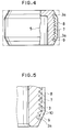
- the helical groove gradually becomes smaller in diameter toward the end in the vicinity of the end of the core material, thereby preventing the helical groove from being exposed over the coating layer even if the upper and lower ends of the coating layer are chamfered.
- the end of the helical groove is stopped before the end of the core material, and is connected with the annular groove, thereby preventing removal even if the chamfered portion is exposed owing to corrosion.
- the tappet according to the present invention comprises the core material in which the helical groove is formed on the outer circumferential surface, and the wear resistant coating layer with which the outer circumferential surface is covered and the ends are chamfered, thereby providing a light weight body and relatively small inertia force, so that response and followability to reciprocal movement is improved. Furthermore; owing to wear resistance in frictional portion, durability will increase.
- the groove of the core material is completely covered with the coating layer other than upper and lower ends, thereby avoiding thinner string portions as in a conventional ones and removal thereof.
- metal thermal spraying it is suggested that the core material is immersed in melted metal, or plating is applied, but metal thermal spraying is more convenient and economical.
- a cylindrical raw material 1 of light metal such as Al as shown in Fig. 1 is rotated on an axis , while a cutting tool contacts the outer circumferential surface 12. Feed is axially given by the cutting tool to form a helical groove 3 on the outer circumferential surface of the raw material 1. At the same time, adjacent to the raw material 1, additional feed is given to the cutting tool toward the axis so that the helical groove 3 gradually decreases in diameter toward the end of the raw material 1.
- Fig. 6 illustrates the second embodiment of a tappet according to the present invention.
- feeds are given to the cutting tool in an axial direction and toward the axis, and the raw material 1 is immediately ground to the end thereof without stopping the feeds at near the end of the material 1, so that the helical groove 3 is formed all over the outer circumferential surface 1, and similar way to the first embodiment is then made.
- the peaks 10 in the helical groove 3 of the material 5 are not exposed over the outer circumferential surface 8 of the coating layer 7.
- the same numerals are alotted to the same members and parts in the first embodiment, and the details thereof are omitted.
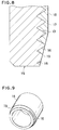
- Fig. 7 illustrates the third embodiment of a tappet according to the present invention.
- feed is given to the cutting tool only in an axial direction, not toward the axis, so that the raw material is ground.
- feed of the cutting tool is stopped, and terminates at a position slightly spaced from the end of the material 1. thereby forming a helical groove 3 having an annular groove 3a at the terminating end then a tappet is made by a way similar to the first embodiment.
Landscapes
- Engineering & Computer Science (AREA)
- Mechanical Engineering (AREA)
- General Engineering & Computer Science (AREA)
- Valve-Gear Or Valve Arrangements (AREA)
Priority Applications (3)
| Application Number | Priority Date | Filing Date | Title |
|---|---|---|---|
| DE1996613959 DE69613959T2 (de) | 1996-05-03 | 1996-05-03 | Ventilstössel einer Brennkraftmaschine und Herstellungsverfahren |
| EP19960303151 EP0806549B1 (fr) | 1996-05-03 | 1996-05-03 | Poussoir de moteur à combustion interne et méthode de fabrication |
| EP00200571A EP1004753B1 (fr) | 1996-05-03 | 1996-05-03 | Poussoir de moteur à combustion interne et sa méthode de fabrication |
Applications Claiming Priority (1)
| Application Number | Priority Date | Filing Date | Title |
|---|---|---|---|
| EP19960303151 EP0806549B1 (fr) | 1996-05-03 | 1996-05-03 | Poussoir de moteur à combustion interne et méthode de fabrication |
Related Child Applications (1)
| Application Number | Title | Priority Date | Filing Date |
|---|---|---|---|
| EP00200571A Division EP1004753B1 (fr) | 1996-05-03 | 1996-05-03 | Poussoir de moteur à combustion interne et sa méthode de fabrication |
Publications (2)
| Publication Number | Publication Date |
|---|---|
| EP0806549A1 true EP0806549A1 (fr) | 1997-11-12 |
| EP0806549B1 EP0806549B1 (fr) | 2001-07-18 |
Family
ID=8224920
Family Applications (2)
| Application Number | Title | Priority Date | Filing Date |
|---|---|---|---|
| EP19960303151 Expired - Lifetime EP0806549B1 (fr) | 1996-05-03 | 1996-05-03 | Poussoir de moteur à combustion interne et méthode de fabrication |
| EP00200571A Expired - Lifetime EP1004753B1 (fr) | 1996-05-03 | 1996-05-03 | Poussoir de moteur à combustion interne et sa méthode de fabrication |
Family Applications After (1)
| Application Number | Title | Priority Date | Filing Date |
|---|---|---|---|
| EP00200571A Expired - Lifetime EP1004753B1 (fr) | 1996-05-03 | 1996-05-03 | Poussoir de moteur à combustion interne et sa méthode de fabrication |
Country Status (2)
| Country | Link |
|---|---|
| EP (2) | EP0806549B1 (fr) |
| DE (1) | DE69613959T2 (fr) |
Families Citing this family (1)
| Publication number | Priority date | Publication date | Assignee | Title |
|---|---|---|---|---|
| DE102013206011A1 (de) | 2013-04-05 | 2014-10-09 | Schaeffler Technologies Gmbh & Co. Kg | Stößel zur Ventil- oder Pumpenbetätigung und Herstellungsverfahren für einen Stößel zur Ventil- oder Pumpenbetätigung |
Citations (3)
| Publication number | Priority date | Publication date | Assignee | Title |
|---|---|---|---|---|
| US3715790A (en) * | 1971-01-13 | 1973-02-13 | Trw Inc | Method of reinforcing piston ring grooves |
| DE3627505A1 (de) * | 1986-08-13 | 1988-02-18 | Motomak | Sich selbsttaetig hydraulisch einstellender ventilstoessel |
| GB2245327A (en) * | 1990-05-17 | 1992-01-02 | T & N Technology Ltd | Tappets |
Family Cites Families (1)
| Publication number | Priority date | Publication date | Assignee | Title |
|---|---|---|---|---|
| JPH07310508A (ja) * | 1994-05-19 | 1995-11-28 | Fuji Oozx Inc | 内燃機関用タペット |
-
1996
- 1996-05-03 DE DE1996613959 patent/DE69613959T2/de not_active Expired - Fee Related
- 1996-05-03 EP EP19960303151 patent/EP0806549B1/fr not_active Expired - Lifetime
- 1996-05-03 EP EP00200571A patent/EP1004753B1/fr not_active Expired - Lifetime
Patent Citations (3)
| Publication number | Priority date | Publication date | Assignee | Title |
|---|---|---|---|---|
| US3715790A (en) * | 1971-01-13 | 1973-02-13 | Trw Inc | Method of reinforcing piston ring grooves |
| DE3627505A1 (de) * | 1986-08-13 | 1988-02-18 | Motomak | Sich selbsttaetig hydraulisch einstellender ventilstoessel |
| GB2245327A (en) * | 1990-05-17 | 1992-01-02 | T & N Technology Ltd | Tappets |
Also Published As
| Publication number | Publication date |
|---|---|
| EP1004753A1 (fr) | 2000-05-31 |
| DE69613959T2 (de) | 2001-12-20 |
| DE69613959D1 (de) | 2001-08-23 |
| EP1004753B1 (fr) | 2002-03-06 |
| EP0806549B1 (fr) | 2001-07-18 |
Similar Documents
| Publication | Publication Date | Title |
|---|---|---|
| US5301874A (en) | Adjusting sleeve for an electromagnetically actuatable valve | |
| US5295696A (en) | Combined oil ring | |
| JP4689923B2 (ja) | 油掻きピストンリングおよび油掻きピストンリングの製造方法 | |
| US4570582A (en) | Inner element for a hydraulic valve play compensating element | |
| GB2093554A (en) | Tappet with ceramic camface | |
| US5455078A (en) | Method of roughening and coating the contact surface of a valve lifter | |
| US5605122A (en) | Tappet in an internal combustion engine and a method of manufacturing it | |
| EP0806549A1 (fr) | Poussoir de moteur à combustion interne et méthode de fabrication | |
| US5729900A (en) | Method of manufacturing a tappet in an internal combustion engine | |
| EP1092886B1 (fr) | Palier lisse muni d'une surface de frottement à motifs en zigzag | |
| EP0828060B1 (fr) | Procédé de fabrication d'un poussoir de moteur à combustion interne | |
| US6203203B1 (en) | Slide bearing having a bearing block and a bearing cap | |
| EP0864731B1 (fr) | Coupelle d'appui de ressort de soupape en alliage d'aluminium | |
| US5809644A (en) | Valve lifter | |
| JPH08200414A (ja) | スプリングインシュレータ構造 | |
| US5743224A (en) | Valve lifter surface and processing method thereof | |
| US5992363A (en) | Valve spring in an internal combustion engine | |
| JP2020504268A (ja) | ヒートエンジンのためのピストン、そうしたピストンを備えるヒートエンジン、および方法 | |
| US5402568A (en) | Method of securing a tip in a tappet | |
| EP4700152A2 (fr) | Insert de chemise de cylindre de barrière thermique | |
| EP0957238B1 (fr) | Ressort de soupape dans un moteur à combustion interne | |
| JP2841422B2 (ja) | 溶射膜の形成方法 | |
| JP3097002B2 (ja) | 内燃機関用タペットのチップ取付方法 | |
| EP0878637A3 (fr) | Ressort hélicoidal revêtu, en particulier pour suspensions de véhicule | |
| US5349748A (en) | Method of manufacturing a tappet for an internal combustion engine |
Legal Events
| Date | Code | Title | Description |
|---|---|---|---|
| PUAI | Public reference made under article 153(3) epc to a published international application that has entered the european phase |
Free format text: ORIGINAL CODE: 0009012 |
|
| AK | Designated contracting states |
Kind code of ref document: A1 Designated state(s): DE FR GB IT |
|
| 17P | Request for examination filed |
Effective date: 19971119 |
|
| 17Q | First examination report despatched |
Effective date: 19991115 |
|
| GRAG | Despatch of communication of intention to grant |
Free format text: ORIGINAL CODE: EPIDOS AGRA |
|
| GRAG | Despatch of communication of intention to grant |
Free format text: ORIGINAL CODE: EPIDOS AGRA |
|
| GRAH | Despatch of communication of intention to grant a patent |
Free format text: ORIGINAL CODE: EPIDOS IGRA |
|
| GRAH | Despatch of communication of intention to grant a patent |
Free format text: ORIGINAL CODE: EPIDOS IGRA |
|
| GRAA | (expected) grant |
Free format text: ORIGINAL CODE: 0009210 |
|
| AK | Designated contracting states |
Kind code of ref document: B1 Designated state(s): DE FR GB IT |
|
| PG25 | Lapsed in a contracting state [announced via postgrant information from national office to epo] |
Ref country code: IT Free format text: LAPSE BECAUSE OF FAILURE TO SUBMIT A TRANSLATION OF THE DESCRIPTION OR TO PAY THE FEE WITHIN THE PRE;WARNING: LAPSES OF ITALIAN PATENTS WITH EFFECTIVE DATE BEFORE 2007 MAY HAVE OCCURRED AT ANY TIME BEFORE 2007. THE CORRECT EFFECTIVE DATE MAY BE DIFFERENT FROM THE ONE RECORDED.SCRIBED TIME-LIMIT Effective date: 20010718 Ref country code: FR Free format text: LAPSE BECAUSE OF FAILURE TO SUBMIT A TRANSLATION OF THE DESCRIPTION OR TO PAY THE FEE WITHIN THE PRESCRIBED TIME-LIMIT Effective date: 20010718 |
|
| REF | Corresponds to: |
Ref document number: 69613959 Country of ref document: DE Date of ref document: 20010823 |
|
| EN | Fr: translation not filed | ||
| REG | Reference to a national code |
Ref country code: GB Ref legal event code: IF02 |
|
| PLBE | No opposition filed within time limit |
Free format text: ORIGINAL CODE: 0009261 |
|
| STAA | Information on the status of an ep patent application or granted ep patent |
Free format text: STATUS: NO OPPOSITION FILED WITHIN TIME LIMIT |
|
| 26N | No opposition filed | ||
| PGFP | Annual fee paid to national office [announced via postgrant information from national office to epo] |
Ref country code: DE Payment date: 20070421 Year of fee payment: 12 |
|
| PGFP | Annual fee paid to national office [announced via postgrant information from national office to epo] |
Ref country code: GB Payment date: 20070502 Year of fee payment: 12 |
|
| GBPC | Gb: european patent ceased through non-payment of renewal fee |
Effective date: 20080503 |
|
| PG25 | Lapsed in a contracting state [announced via postgrant information from national office to epo] |
Ref country code: DE Free format text: LAPSE BECAUSE OF NON-PAYMENT OF DUE FEES Effective date: 20081202 |
|
| PG25 | Lapsed in a contracting state [announced via postgrant information from national office to epo] |
Ref country code: GB Free format text: LAPSE BECAUSE OF NON-PAYMENT OF DUE FEES Effective date: 20080503 |