EP0806558A2 - Device to use an annular gas turbine combustor with liquid and gasseous fuels - Google Patents
Device to use an annular gas turbine combustor with liquid and gasseous fuels Download PDFInfo
- Publication number
- EP0806558A2 EP0806558A2 EP97810225A EP97810225A EP0806558A2 EP 0806558 A2 EP0806558 A2 EP 0806558A2 EP 97810225 A EP97810225 A EP 97810225A EP 97810225 A EP97810225 A EP 97810225A EP 0806558 A2 EP0806558 A2 EP 0806558A2
- Authority
- EP
- European Patent Office
- Prior art keywords
- burner
- fuel
- air
- gas
- liquid
- Prior art date
- Legal status (The legal status is an assumption and is not a legal conclusion. Google has not performed a legal analysis and makes no representation as to the accuracy of the status listed.)
- Withdrawn
Links
- 239000000446 fuel Substances 0.000 title claims abstract description 59
- 239000007788 liquid Substances 0.000 title claims description 26
- 230000007246 mechanism Effects 0.000 claims abstract description 9
- 238000002485 combustion reaction Methods 0.000 claims description 20
- 238000000889 atomisation Methods 0.000 abstract description 7
- 239000012530 fluid Substances 0.000 abstract 2
- 239000007789 gas Substances 0.000 description 33
- 239000003921 oil Substances 0.000 description 4
- 239000002737 fuel gas Substances 0.000 description 3
- 239000000203 mixture Substances 0.000 description 3
- 230000008901 benefit Effects 0.000 description 2
- 230000001276 controlling effect Effects 0.000 description 2
- 238000010586 diagram Methods 0.000 description 2
- 238000000034 method Methods 0.000 description 2
- 238000011144 upstream manufacturing Methods 0.000 description 2
- 241001156002 Anthonomus pomorum Species 0.000 description 1
- 230000006978 adaptation Effects 0.000 description 1
- 238000005516 engineering process Methods 0.000 description 1
- 239000000295 fuel oil Substances 0.000 description 1
- 238000009434 installation Methods 0.000 description 1
- 230000008569 process Effects 0.000 description 1
- 230000009467 reduction Effects 0.000 description 1
- 230000001105 regulatory effect Effects 0.000 description 1
Images
Classifications
-
- F—MECHANICAL ENGINEERING; LIGHTING; HEATING; WEAPONS; BLASTING
- F02—COMBUSTION ENGINES; HOT-GAS OR COMBUSTION-PRODUCT ENGINE PLANTS
- F02C—GAS-TURBINE PLANTS; AIR INTAKES FOR JET-PROPULSION PLANTS; CONTROLLING FUEL SUPPLY IN AIR-BREATHING JET-PROPULSION PLANTS
- F02C7/00—Features, components parts, details or accessories, not provided for in, or of interest apart form groups F02C1/00 - F02C6/00; Air intakes for jet-propulsion plants
- F02C7/22—Fuel supply systems
- F02C7/222—Fuel flow conduits, e.g. manifolds
-
- F—MECHANICAL ENGINEERING; LIGHTING; HEATING; WEAPONS; BLASTING
- F02—COMBUSTION ENGINES; HOT-GAS OR COMBUSTION-PRODUCT ENGINE PLANTS
- F02C—GAS-TURBINE PLANTS; AIR INTAKES FOR JET-PROPULSION PLANTS; CONTROLLING FUEL SUPPLY IN AIR-BREATHING JET-PROPULSION PLANTS
- F02C7/00—Features, components parts, details or accessories, not provided for in, or of interest apart form groups F02C1/00 - F02C6/00; Air intakes for jet-propulsion plants
- F02C7/22—Fuel supply systems
- F02C7/232—Fuel valves; Draining valves or systems
-
- F—MECHANICAL ENGINEERING; LIGHTING; HEATING; WEAPONS; BLASTING
- F23—COMBUSTION APPARATUS; COMBUSTION PROCESSES
- F23R—GENERATING COMBUSTION PRODUCTS OF HIGH PRESSURE OR HIGH VELOCITY, e.g. GAS-TURBINE COMBUSTION CHAMBERS
- F23R3/00—Continuous combustion chambers using liquid or gaseous fuel
- F23R3/28—Continuous combustion chambers using liquid or gaseous fuel characterised by the fuel supply
- F23R3/36—Supply of different fuels
Definitions
- the invention relates to the field of combustion technology. It relates to a device for operating an annular combustion chamber for gas turbines, which is equipped with combined burners for liquid and gaseous fuels, in particular burners of the double-cone type, each burner having an airblast nozzle for atomizing the liquid fuel, into which atomizing air is fed from outside the burner hood is and wherein the inflow of atomizing air is at least partially throttled during gas operation.
- burners are operated close to their lean extinguishing limit.
- internal piloting is used, for example, in the case of part-load operation of a gas turbine, in which the fuel gases near the axis are enriched with additional fuel. This extends the stability range of the burners to such an extent that safe operation is guaranteed even under partial load conditions.
- the atomizing air is not only injected during the fuel oil atomization, but also in gas operation, in which, however, no air is required for atomization.
- this additional air destabilizes the flame, on the one hand, through leaning and, on the other hand, through the inflow itself. This in turn leads to a significant reduction in the lean extinguishing limit of the gas flame.
- the airblast nozzle is designed such that the pilot gas channel opens into at least one atomizing air channel before the atomizing cross section, so that the atomizing air is throttled off by means of the pilot gas.
- This design has the disadvantage that when the burner is operated with gaseous fuel, it is necessary to work continuously with additional pilot gas not only during the starting phase.
- an adjustment mechanism for example in the form of a displaceable or rotatable sleeve, is arranged on the fuel lance or the fuel nozzle, which acts when the burner is operated with gaseous fuel at least partially closes the air inlet opening of the atomizing air.
- the invention tries to avoid all of these disadvantages. It is the object of the invention to provide a simple device for operating an annular combustion chamber equipped with combined burners for liquid and gaseous fuels for the purpose of hot gas generation, with which a separate control of the atomizing air is made possible, so that the lean extinguishing limit of the gas flame without impairing the atomization of the liquid Fuel is increased.
- the device should work reliably and allow trouble-free switching between gas and oil operation of the burners.
- the advantages of the invention are that the flow of atomizing air can be controlled in a simple manner outside the nozzle or the burner and can thus be optimally adapted to the respective operating conditions. It is possible to switch between gas and oil operation of the burner, with oil operation the valve is opened so far that the required atomizing air enters the airblast nozzle unhindered, while with gas operation of the burner the valve is either completely closed and thus the inflow of Atomizing air is prevented or the valve is partially closed, so that only a certain amount of air that hardly influences the flame stability gets into the fuel lance.
- the external arrangement of the control system also ensures that it can work reliably at high operating temperatures inside the machine.
- the ring line is arranged outside on the housing of the gas turbine. This enables easy installation and easy access.
- an embodiment of the invention is shown on the basis of an annular combustion chamber equipped with combined burners for liquid and gaseous burners, which provides the hot gas required for charging a gas turbine.
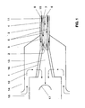
- Fig. 1 shows schematically a burner 1 of the double-cone type. Its basic structure is described in detail in EP 0 321 809 B1, so that it is therefore omitted here.
- An airblast nozzle 2 is arranged in the upstream end of the burner 1.
- the airblast nozzle 2 is supplied with liquid fuel 4 and atomizing air 5 via a fuel lance 3 connected to the double-cone burner 1.
- a liquid fuel channel 6 and an atomizing air channel 7 are arranged in the fuel lance 3.
- the fuel lance 3 delivers via a gas channel 8 the gaseous fuel 9 for the burner 1.
- pilot gas 9 can be injected near the axis of the double-cone burner to enrich the fuel gases.
- the combustion air 12 is fed to the burner 1 from the space inside the burner hood 13, which is connected to an air plenum 14.
- the burner 1 opens into the combustion chamber 15 downstream.
- gaseous fuel 9 When operating with gaseous fuel 9, the inflow of atomizing air 5, as will be described below, is throttled or completely prevented.
- the gaseous fuel 9 is therefore pre-mixed undisturbed with the combustion air 12 flowing into the burner interior 16 via the tangential air inlet slots. Downstream of the burner mouth, a backflow zone 17 forms, at the tip of which the fuel / air mixture is ignited. A stable flame front then forms at this point.
- pilot gas 11 is supplied to the nozzle 2 through the pilot gas channel 10. The fuel gases are enriched by this additional fuel 11 and the stability range of the burner 1 is expanded.
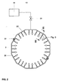
- FIG. 2 shows a schematic diagram of the device according to the invention.
- the annular combustion chamber 15 is arranged between a compressor, not shown here, and a turbine, also not shown.
- a line 19 is connected to the compressor outlet 18 of the gas turbine system, which is shown schematically in FIG. 2, which leads to a ring line 20 and is connected to the latter.
- the line 19 represents the main supply line for the atomizing air 5.
- a valve 21 is arranged in the line 19, with which the amount of the atomizing air 5 flowing into the ring line 20 can be regulated.
- the ring line 20 is mounted on the outside of the housing of the gas turbine, it leads around the entire machine. For reasons of assembly, the ring line 20 is divided, its two halves are connected to one another by means of flanges 22.
- 20 branch lines 23 branch off from the ring line 20.
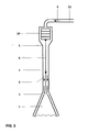
- One of these branch lines 23 is connected at its other end to the head 24 of a fuel lance 3. This can be seen particularly clearly in the enlarged detail according to FIG. 3.
- the valve 21 is opened.
- the atomizing air 5 required for atomizing the liquid fuel 4 in the airblast nozzle can therefore pass freely into the ring line 20 and from there via the branch lines 23 into the lance heads 24.
- the air 5 then flows through the atomizing air channel 7 present in the fuel lance 3 into the airblast nozzle 2, where it is used to atomize the liquid fuel 4.
- the atomized liquid fuel 4 is then premixed with the main combustion air 12 and the mixture is finally burned in the combustion chamber 15, with only low NOx emissions occurring.
- valve 21 is at least partially closed, so that only a certain proportion of air 5 reaches the fuel lance 3 through the lines 19, 20 and 23.
- the gas flame is not destabilized. It is easy to switch between gas and oil operation. It is not necessary to replace the fuel lances during the switchover process.
- Controlling the air supply via an external valve also has the advantage of good accessibility and good operational safety because the adjustment mechanism can be operated outside the machine. This is particularly important because in the course of constant efficiency improvements, gas turbines are now operated at ever higher temperatures.
Landscapes
- Engineering & Computer Science (AREA)
- Chemical & Material Sciences (AREA)
- Combustion & Propulsion (AREA)
- Mechanical Engineering (AREA)
- General Engineering & Computer Science (AREA)
- Nozzles For Spraying Of Liquid Fuel (AREA)
- Spray-Type Burners (AREA)
Abstract
Description
Die Erfindung bezieht sich auf das Gebiet der Verbrennungstechnik. Sie betrifft eine Vorrichtung zum Betreiben einer Ringbrennkammer für Gasturbinen, welche mit kombinierten Brennern für flüssige und gasförmige Brennstoffe, insbesondere Brennern der Doppelkegelbauart bestückt ist, wobei jeder Brenner eine Airblast-Düse zum Zerstäuben des flüssigen Brennstoffes aufweist, in welche Zerstäubungsluft von ausserhalb der Brennerhaube zugeführt wird und wobei der Zustrom der Zerstäubungsluft bei Gasbetrieb zumindestens teilweise abgedrosselt wird.The invention relates to the field of combustion technology. It relates to a device for operating an annular combustion chamber for gas turbines, which is equipped with combined burners for liquid and gaseous fuels, in particular burners of the double-cone type, each burner having an airblast nozzle for atomizing the liquid fuel, into which atomizing air is fed from outside the burner hood is and wherein the inflow of atomizing air is at least partially throttled during gas operation.
Zur Erzielung möglichst niedriger NOx-Emissionen werden Brenner nahe ihrer mageren Löschgrenze betrieben. Dadurch wird allerdings der Regelbereich der Brenner stark eingeschränkt. Um diesen Nachteil zu beseitigen, wird beispielsweise bei Teillastbetrieb einer Gasturbine eine interne Pilotierung angewendet, bei der die Brenngase in Achsnähe mit zusätzlichem Brennstoff angefettet werden. Dadurch wird der Stabilitätsbereich der Brenner so weit erweitert, dass ein sicherer Betrieb auch bei Teillastbedingungen gewährleistet ist.To achieve the lowest possible NOx emissions, burners are operated close to their lean extinguishing limit. However, this severely limits the burner control range. In order to eliminate this disadvantage, internal piloting is used, for example, in the case of part-load operation of a gas turbine, in which the fuel gases near the axis are enriched with additional fuel. This extends the stability range of the burners to such an extent that safe operation is guaranteed even under partial load conditions.
Zum wahlweisen Betrieb eines Brenners mit gasförmigem oder flüssigem Brennstoff ist es bekannt, den flüssigen Brennstoff mit Hilfe einer Airblast-Düse zu zerstäuben. Dazu wird in Achsnähe, d.h. im Zentrum des Brenners Luft eingedüst. Diese Zerstäubungsluft wird ebenso wie die Verbrennungsluft bei Vormischbrennern der Doppelkegelbauart, deren prinzipieller Aufbau in EP 0 321 809 B1 beschrieben ist, einem ausserhalb des Brenners angeordnetem Plenum entnommen.For the optional operation of a burner with gaseous or liquid fuel, it is known to atomize the liquid fuel using an airblast nozzle. To do this, close to the axis, i.e. Air is injected into the center of the burner. This atomizing air, like the combustion air in premix burners of the double-cone type, the basic structure of which is described in EP 0 321 809 B1, is taken from a plenum arranged outside the burner.
Die Eindüsung der Zerstäubungsluft geschieht aber nicht nur bei der Brennölzerstäubung, sondern auch im Gasbetrieb, bei dem jedoch gar keine Luft zur Zerstäubung notwendig ist. Im Gasbetrieb des Brenners destabilisiert diese zusätzliche Luft die Flamme zum einen durch Abmagerung und zum anderen durch die Anströmung selbst. Das führt wiederum zu einer deutlichen Herabsetzung der mageren Löschgrenze der Gasflamme.The atomizing air is not only injected during the fuel oil atomization, but also in gas operation, in which, however, no air is required for atomization. When the burner is operating in gas mode, this additional air destabilizes the flame, on the one hand, through leaning and, on the other hand, through the inflow itself. This in turn leads to a significant reduction in the lean extinguishing limit of the gas flame.
Aus DE 44 24 599 A1 sind ein Verfahren und mehrere Vorrichtungen zum Betreiben eines kombinierten Brenners für flüssige und gasförmige Brennstoffe bekannt, bei denen dieser Nachteil beseitigt wird, indem eine Steuerung des Zustromes der Zerstäubungsluft vorgesehen ist, wobei beim Betrieb mit gasförmigen Brennstoff der Zustrom der Zerstäubungsluft zumindest teilweise abgedrosselt wird.From DE 44 24 599 A1 a method and several devices for operating a combined burner for liquid and gaseous fuels are known, in which this disadvantage is eliminated by controlling the inflow of the atomizing air, the inflow of the gas being used when operating with gaseous fuel Atomizing air is at least partially throttled.
Dazu ist gemäss DE 44 24 599 A1 beispielsweise die Airblast-Düse so ausgebildet, dass der Pilotgaskanal vor dem Zerstäubungsquerschnitt in mindestens einen Zerstäubungsluftkanal mündet, so dass das Abdrosseln der Zerstäubungsluft mittels des Pilotgases erfolgt. Diese Ausführung hat den Nachteil, dass beim Betrieb des Brenners mit gasförmigem Brennstoff nicht nur während der Startphase, sondern ständig mit zusätzlichem Pilotgas gearbeitet werden muss.For this purpose, according to DE 44 24 599 A1, for example, the airblast nozzle is designed such that the pilot gas channel opens into at least one atomizing air channel before the atomizing cross section, so that the atomizing air is throttled off by means of the pilot gas. This design has the disadvantage that when the burner is operated with gaseous fuel, it is necessary to work continuously with additional pilot gas not only during the starting phase.
In einer anderen in DE 44 24 599 A1 beschriebenen Ausführung, bei welcher der Brenner in der Brennerhaube durch einen Brennerstutzen mit integrierter Lufteintrittsöffnung für die Gebläseluft befestigt ist und zur Zufuhr des flüssigen Brennstoffes am Brennerstutzen stromaufwärts eine Brennstofflanze anschliesst, ist auf der Brennstofflanze oder dem Brennstutzen ein Verstellmechanismus, z.B. in Form einer verschiebbaren oder drehbaren Hülse, angeordnet, der beim Betreiben des Brenners mit gasförmigen Brennstoff die Lufteintrittsöffnung der Zerstäubungsluft zumindestens teilweise verschliesst. Diese Lösung hat den Nachteil, dass der Verstellmechanismus im Inneren der Maschine angeordnet ist und daher schwer zugänglich ist.In another embodiment described in DE 44 24 599 A1, in which the burner in the burner hood is through a burner nozzle with an integrated air inlet opening for the blower air and a fuel lance connected upstream to supply the liquid fuel to the burner nozzle, an adjustment mechanism, for example in the form of a displaceable or rotatable sleeve, is arranged on the fuel lance or the fuel nozzle, which acts when the burner is operated with gaseous fuel at least partially closes the air inlet opening of the atomizing air. This solution has the disadvantage that the adjustment mechanism is arranged inside the machine and is therefore difficult to access.
Aus GB 2 091 409 A ist eine Airblast-Düse bekannt, bei der der Zustrom der Verbrennungs- und der Zerstäubungsluft entsprechend dem Bedarf der Brennkammer gemeinsam gesteuert wird. Dazu sind zwei unterschiedliche Dosierventile angeordnet, die von einem gemeinsamen Kolben beaufschlagt werden. Diese Lösung hat den Nachteil, dass keine separate Steuerung der Zerstäubungsluft möglich ist. Ausserdem sind die Ventile unmittelbar an der Düse angeordnet und somit hohen Temperaturen ausgesetzt.From
Die Erfindung versucht, alle diese Nachteile zu vermeiden. Ihr liegt die Aufgabe zugrunde, eine einfache Vorrichtung zum Betreiben einer mit kombinierten Brennern für flüssige und gasförmige Brennstoffe zwecks Heissgaserzeugung bestückten Ringbrennkammer zu schaffen, mit der eine separate Steuerung der Zerstäubungsluft ermöglicht wird, so dass die magere Löschgrenze der Gasflammme ohne Beeinträchtigung der Zerstäubung des flüssigen Brennstoffes heraufgesetzt wird. Die Vorrichtung soll zuverlässig arbeiten und ein problemloses Umschalten zwischen Gas- und Ölbetrieb der Brenner ermöglichen.The invention tries to avoid all of these disadvantages. It is the object of the invention to provide a simple device for operating an annular combustion chamber equipped with combined burners for liquid and gaseous fuels for the purpose of hot gas generation, with which a separate control of the atomizing air is made possible, so that the lean extinguishing limit of the gas flame without impairing the atomization of the liquid Fuel is increased. The device should work reliably and allow trouble-free switching between gas and oil operation of the burners.
Erfindungsgemäss wird dies bei einer Vorrichtung zum Betreiben einer mit kombinierten Brennern für flüssige und gasförmige Brennstoffe, insbesondere Brennern der Doppelkegelbauart, bestückten Ringbrennkammer, wobei jeder Brenner zur Zufuhr des flüssigen Brennstoffes eine Brennstofflanze mit zusätzlichen Luftkanälen und zum Zerstäuben des flüssigen Brennstoffes eine Airblast-Düse aufweist, in welche Zerstäubungsluft von ausserhalb der Brennerhaube zugeführt wird, und ein Verstellmechanismus zur zumindestens teilweisen Abdrosselung des Zustromes der Zerstäubungsluft bei Gasbetrieb vorgesehen ist, dadurch erreicht, dass der Verstellmechanismus ein externes Ventil ist, welches in einer vom Verdichteraustritt kommenden Hauptzufuhrleitung für die Zerstäubungsluft angeordnet ist, wobei die Hauptzufuhrleitung in eine Ringleitung mündet, und die Ringleitung über jeweils eine Stichleitung mit dem Kopf jeder Brennstofflanze verbunden ist.According to the invention, this becomes in a device for operating an annular combustion chamber equipped with combined burners for liquid and gaseous fuels, in particular burners of the double cone type, each burner having a fuel lance with additional air channels for supplying the liquid fuel and an airblast nozzle for atomizing the liquid fuel , into which atomizing air is fed from outside the burner hood, and an adjustment mechanism for at least partially throttling off the inflow of atomizing air during gas operation is achieved in that the adjusting mechanism is an external valve which is arranged in a main supply line for the atomizing air coming from the compressor outlet , wherein the main feed line opens into a ring line, and the ring line is connected via a branch line to the head of each fuel lance.
Die Vorteile der Erfindung bestehen darin, dass der Zustrom der Zerstäubungsluft auf einfache Art und Weise ausserhalb der Düse bzw. des Brenners gesteuert und somit optimal auf die jeweiligen Betriebsbedingungen angepasst werden kann. Es kann wahlweise zwischen Gas- und Ölbetrieb des Brenners umgeschaltet werden, wobei bei Ölbetrieb das Ventil so weit geöffnet wird, dass die benötigte Zerstäubungsluft ungehindert in die Airblast-Düse gelangt, während bei Gasbetrieb des Brenners das Ventil entweder ganz geschlossen und damit der Zustrom der Zerstäubungsluft verhindert wird oder das Ventil wird teilweise geschlossen, so dass nur ein bestimmter, die Flammenstabilität kaum beeinflussender Anteil Luft in die Brennstofflanze gelangt. Durch die externe Anordnung des Steuersystems ist auch sein zuverlässiges Arbeiten bei hohen Betriebstemperaturen im Inneren der Maschine gewährleistet.The advantages of the invention are that the flow of atomizing air can be controlled in a simple manner outside the nozzle or the burner and can thus be optimally adapted to the respective operating conditions. It is possible to switch between gas and oil operation of the burner, with oil operation the valve is opened so far that the required atomizing air enters the airblast nozzle unhindered, while with gas operation of the burner the valve is either completely closed and thus the inflow of Atomizing air is prevented or the valve is partially closed, so that only a certain amount of air that hardly influences the flame stability gets into the fuel lance. The external arrangement of the control system also ensures that it can work reliably at high operating temperatures inside the machine.
Es ist besonders zweckmässig, wenn die Ringleitung ausserhalb am Gehäuse der Gasturbine angeordnet ist. Das ermöglicht ein einfache Montage und eine problemlose Zugänglichkeit.It is particularly expedient if the ring line is arranged outside on the housing of the gas turbine. This enables easy installation and easy access.
In der Zeichnung ist ein Ausführungsbeispiel der Erfindung anhand einer mit kombinierten Brennern für flüssige und gasförmige Brenner bestückten Ringbrennkammer, welche das zur Beaufschlagung einer Gasturbine benötigte Heissgas bereitstellt, dargestellt.In the drawing, an embodiment of the invention is shown on the basis of an annular combustion chamber equipped with combined burners for liquid and gaseous burners, which provides the hot gas required for charging a gas turbine.
Es zeigen:
- Fig. 1
- eine schematische Darstellung der Anordnung eines mit einer Airblast-Düse ausgestatteten Brenners;
- Fig. 2
- eine Prinzipskizze der erfindungsgemässen Vorrichtung;
- Fig. 3
- ein vergrössertes Detail aus Fig 2.
- Fig. 1
- is a schematic representation of the arrangement of a burner equipped with an airblast nozzle;
- Fig. 2
- a schematic diagram of the inventive device;
- Fig. 3
- an enlarged detail from FIG. 2.
Es sind nur die für das Verständnis der Erfindung wesentlichen Elemente gezeigt. Die Strömungsrichtung der Arbeitsmittel ist mit Pfeilen bezeichnet.Only the elements essential for understanding the invention are shown. The direction of flow of the work equipment is indicated by arrows.
Nachfolgend wird die Erfindung anhand eines Ausführungsbeispieles und der Fig. 1 bis 3 näher erläutert.The invention is explained in more detail below using an exemplary embodiment and FIGS. 1 to 3.
Fig. 1 zeigt schematisch einen Brenner 1 der Doppelkegelbauart. Dessen prinzipieller Aufbau ist ausführlich in EP 0 321 809 B1 beschrieben, so dass hier deshalb darauf verzichtet wird. Im stromaufwärtigen Ende des Brenners 1 ist eine Airblast-Düse 2 angeordnet. Die Airblast-Düse 2 wird über eine mit dem Doppelkegelbrenner 1 verbundene Brennstofflanze 3 mit flüssigem Brennstoff 4 und mit Zerstäubungsluft 5 versorgt. Aus diesem Grunde sind in der Brennstofflanze 3 ein Flüssigbrennstoffkanal 6 und ein Zerstäubungsluftkanal 7 angeordnet. Ausserdem liefert die Brennstofflanze 3 über einen Gaskanal 8 den gasförmigen Brennstoff 9 für den Brenner 1. Schliesslich kann über einen in der Brennstofflanze 3 angeordneten Pilotgaskanal 10 zusätzlich gasförmiger Brennstoff, sogenanntes Pilotgas 9, zum Anfetten der Brenngase in Achsnähe des Doppelkegelbrenners eingedüst werden. Die Verbrennungsluft 12 wird dem Brenner 1 aus dem Raum innerhalb der Brennerhaube 13, welche mit einem Luftplenum 14 in Verbindung steht, zugeführt. Stromabwärts mündet der Brenner 1 in die Brennkammer 15.Fig. 1 shows schematically a
Beim Betrieb mit flüssigem Brennstoff 4 wird dieser über den in der Brennstofflanze 3 zentral angeordneten Flüssigbrennstoffkanal 6 in die Airblast-Düse 2 geführt und dort mittels der über den Zerstäubungsluftkanal 7 zugeführten Zerstäubungsluft 5 fein zerstäubt. Anschliessend gelangt der so zerstäubte Brennstoff 4 zwecks Vormischung mit der über die tangentialen Lufteintrittsschlitze des Doppelkegelbrenners 1 einströmenden Verbrennungsluft 12 in den Brennerinnenraum 16. Das Gemisch verbrennt schliesslich in der Brennkammer 15.When operating with
Beim Betrieb mit gasförmigen Brennstoff 9 wird der Zustrom der Zerstäubungsluft 5, wie weiter unten beschrieben wird, abgedrosselt bzw. ganz unterbunden. Der gasförmige Brennstoff 9 wird daher ungestört mit der über die tangentialen Lufteintrittsschlitze in den Brennerinnenraum 16 einströmenden Verbrennungsluft 12 vorgemischt. Stromabwärts der Brennermündung bildet sich eine Rückströmzone 17 aus, an deren Spitze die Zündung des Brennstoff/Luft-Gemisches erfolgt. An dieser Stelle bildet sich dann eine stabile Flammenfront aus. Um auch beim Start bzw. bei Teillastbedingungen ein stabiles Brennen der Flamme zu gewährleisten, wird durch den Pilotgaskanal 10 der Düse 2 Pilotgas 11 zugeführt. Durch diesen zusätzlichen Brennstoff 11 werden die Brenngase angefettet und der Stabilitätsbereich des Brenners 1 wird erweitert.When operating with
Fig. 2 zeigt eine Prinzipskizze der erfindungsgemässen Vorrichtung. Die Ringbrennkammer 15 ist zwischen einem hier nicht dargestellten Verdichter und einer ebenfalls nicht dargestellten Turbine angeordnet. Am in Fig. 2 schematisch dargestellten Verdichteraustritt 18 der Gasturbinenanlage ist eine Leitung 19 angeschlossen, die zu einer Ringleitung 20 führt und mit dieser verbunden ist. Die Leitung 19 stellt die Hauptzufuhrleitung für die Zerstäubungsluft 5 dar. In der Leitung 19 ist ein Ventil 21 angeordnet, mit welchem sich die Menge der in die Ringleitung 20 strömenden Zerstäubungsluft 5 regulieren lässt. Die Ringleitung 20 ist aussen am Gehäuse der Gasturbine montiert, sie führt um die ganze Maschine herum. Aus Montagegründen ist die Ringleitung 20 geteilt, ihre beiden Hälften sind mit Hilfe von Flanschen 22 miteinander verbunden. Von der Ringleitung 20 zweigen gemäss dem in Fig. 2 dargestellten Ausführungsbeispiel 20 Stichleitungen 23 ab. Jeweils eine dieser Stichleitungen 23 ist an ihrem anderen Ende mit dem Kopf 24 einer Brennstofflanze 3 verbunden. Dies ist besonders deutlich in dem vergrösserten Detail gemäss Fig. 3 zu erkennen.2 shows a schematic diagram of the device according to the invention. The
Werden die Brenner 1 der Ringbrennkammer 15 mit flüssigem Brennstoff 4 betrieben, so wird das Ventil 21 geöffnet. Die zur Zerstäubung des flüssigen Brennstoffes 4 in der Airblast-Düse benötigte Zerstäubungsluft 5 kann deshalb ungehindert in die Ringleitung 20 und von dort aus über die Stichleitungen 23 in die Lanzenköpfe 24 gelangen. Anschliessend strömt die Luft 5 durch den in der Brennstofflanze 3 vorhandenen Zerstäubungsluftkanal 7 in die Airblast-Düse 2, wo sie zur Zerstäubung des flüssigen Brennstoffes 4 benutzt wird. Der zerstäubte flüssige Brennstoff 4 wird danach mit der Haupt-Verbrennungsluft 12 vorgemischt und das Gemisch schliesslich in der Brennkammer 15 verbrannt, wobei nur geringe NOx-Emissionen auftreten.If the
Wird nun auf Gasbetrieb umgestellt, dann wird das Ventil 21 zumindestens teilweise geschlossen, so dass nur ein bestimmter Anteil an Luft 5 durch die Leitungen 19, 20 und 23 in die Brennstofflanze 3 gelangt. Selbstverständlich ist es auch möglich, durch vollständiges Schliessen des Ventiles 21 den Zustrom der Zerstäubungsluft 5 völlig zu unterbinden. Auf diese Weise ist es möglich, die zuzuführende Luftmenge sehr einfach zu steuern und eine schnelle Anpassung auf die jeweiligen Betriebsbedingungen zu erreichen. Die Gasflamme wird nicht destablisiert. Es kann problemlos zwischen Gas- und Ölbetrieb umgeschaltet werden. Beim Umschaltvorgang ist kein Austauschen der Brennstofflanzen nötig. Die Steuerung der Luftzufuhr über ein externes Ventil hat ausserdem den Vorteil einer guten Zugänglichkeit und einer guten Betriebssicherheit, weil der Verstellmechanismus ausserhalb der Maschine betätigt werden kann. Das ist besonders wichtig, weil im Zuge der ständigen Wirkungsgradverbesserungen heutzutage Gasturbinen bei immer höheren Temperaturen betrieben werden.If a switch is now made to gas operation, the
- 11
- Brennerburner
- 22nd
- Airblast-DüseAirblast nozzle
- 33rd
- BrennstofflanzeFuel lance
- 44th
- flüssiger Brennstoffliquid fuel
- 55
- ZerstäubungsluftAtomizing air
- 66
- FlüssigbrennstoffkanalLiquid fuel channel
- 77
- ZerstäubunasluftkanalAtomizing air duct
- 88th
- GaskanalGas channel
- 99
- gasförmiger Brennstoffgaseous fuel
- 1010th
- PilotgaskanalPilot gas duct
- 1111
- PilotgasPilot gas
- 1212th
- VerbrennungsluftCombustion air
- 1313
- BrennerhaubeBurner hood
- 1414
- Plenumplenum
- 1515
- BrennkammerCombustion chamber
- 1616
- BrennerinnenraumBurner interior
- 1717th
- RückströmzoneBackflow zone
- 1818th
- VerdichteraustrittCompressor outlet
- 1919th
-
Hauptzufuhrleitung für Pos. 5Main supply line for
item 5 - 2020th
- RingleitungLoop
- 2121
- VentilValve
- 2222
- Flanschflange
- 2323
- StichleitungBranch line
- 2424th
-
Kopf von Pos. 3Head of
item 3
Claims (2)
Applications Claiming Priority (2)
| Application Number | Priority Date | Filing Date | Title |
|---|---|---|---|
| DE19618856 | 1996-05-10 | ||
| DE19618856A DE19618856B4 (en) | 1996-05-10 | 1996-05-10 | Device for operating an annular combustion chamber equipped with combined burners for liquid and gaseous fuels |
Publications (1)
| Publication Number | Publication Date |
|---|---|
| EP0806558A2 true EP0806558A2 (en) | 1997-11-12 |
Family
ID=7793944
Family Applications (1)
| Application Number | Title | Priority Date | Filing Date |
|---|---|---|---|
| EP97810225A Withdrawn EP0806558A2 (en) | 1996-05-10 | 1997-04-15 | Device to use an annular gas turbine combustor with liquid and gasseous fuels |
Country Status (4)
| Country | Link |
|---|---|
| US (1) | US5884471A (en) |
| EP (1) | EP0806558A2 (en) |
| JP (1) | JPH1054557A (en) |
| DE (1) | DE19618856B4 (en) |
Cited By (1)
| Publication number | Priority date | Publication date | Assignee | Title |
|---|---|---|---|---|
| EP4621294A1 (en) * | 2024-03-19 | 2025-09-24 | Rolls-Royce Deutschland Ltd & Co KG | Injector assembly for a gas turbine and aircraft |
Families Citing this family (15)
| Publication number | Priority date | Publication date | Assignee | Title |
|---|---|---|---|---|
| DE19652899A1 (en) * | 1996-12-19 | 1998-06-25 | Asea Brown Boveri | Burner arrangement for a gas turbine |
| EP0918190A1 (en) * | 1997-11-21 | 1999-05-26 | Abb Research Ltd. | Burner for the operation of a heat generator |
| DE19829398A1 (en) * | 1998-07-01 | 2000-01-05 | Asea Brown Boveri | Gas turbine with reduced noise operation |
| ATE249577T1 (en) * | 1999-02-24 | 2003-09-15 | Kema Nv | COMBUSTION DEVICE AND POWER PLANT WITH SUCH A COMBUSTION DEVICE |
| DE10049203A1 (en) * | 2000-10-05 | 2002-05-23 | Alstom Switzerland Ltd | Process for introducing fuel into a premix burner |
| DE10050248A1 (en) * | 2000-10-11 | 2002-04-18 | Alstom Switzerland Ltd | Pre-mixing burner comprises swirl burner with inner chamber, with widening passage, injector with adjustable elements. |
| ES2295423T3 (en) * | 2001-12-20 | 2008-04-16 | Alstom Technology Ltd | PROCEDURE FOR INJECTION OF A FUEL / AIR MIXTURE IN A COMBUSTION CHAMBER. |
| US7117675B2 (en) * | 2002-12-03 | 2006-10-10 | General Electric Company | Cooling of liquid fuel components to eliminate coking |
| US7533531B2 (en) * | 2005-04-01 | 2009-05-19 | Pratt & Whitney Canada Corp. | Internal fuel manifold with airblast nozzles |
| US8413446B2 (en) * | 2008-12-10 | 2013-04-09 | Caterpillar Inc. | Fuel injector arrangement having porous premixing chamber |
| JP6664389B2 (en) * | 2014-10-23 | 2020-03-13 | シーメンス アクチエンゲゼルシヤフトSiemens Aktiengesellschaft | Flexible fuel combustion system for turbine engines |
| EP3073097B1 (en) * | 2015-03-27 | 2019-06-12 | Ansaldo Energia Switzerland AG | Integrated dual fuel delivery system |
| CN113803744B (en) * | 2021-09-27 | 2023-03-10 | 中国联合重型燃气轮机技术有限公司 | Combustion chamber feeding device and feeding system |
| US12162618B2 (en) | 2021-10-11 | 2024-12-10 | Boom Technology, Inc. | Dissimilarly shaped aircraft nozzles with tandem mixing devices, and associated systems and methods |
| DE102022207492A1 (en) * | 2022-07-21 | 2024-02-01 | Rolls-Royce Deutschland Ltd & Co Kg | Nozzle device for adding at least one gaseous fuel and one liquid fuel, set, supply system and gas turbine arrangement |
Family Cites Families (10)
| Publication number | Priority date | Publication date | Assignee | Title |
|---|---|---|---|---|
| US1338679A (en) * | 1919-02-15 | 1920-05-04 | Neville C Davison | Fuel-burner |
| US2595759A (en) * | 1948-11-30 | 1952-05-06 | Gen Electric | Atomizing nozzle for spraying viscous liquids |
| US3668869A (en) * | 1971-01-28 | 1972-06-13 | Westinghouse Electric Corp | Fuel spray ignition atomizer nozzle |
| US3763650A (en) * | 1971-07-26 | 1973-10-09 | Westinghouse Electric Corp | Gas turbine temperature profiling structure |
| CA1188111A (en) * | 1980-12-02 | 1985-06-04 | William F. Helmrich | Variable area means for air systems of air blast type fuel nozzle assemblies |
| US4903478A (en) * | 1987-06-25 | 1990-02-27 | General Electric Company | Dual manifold fuel system |
| CH674561A5 (en) * | 1987-12-21 | 1990-06-15 | Bbc Brown Boveri & Cie | |
| US5097666A (en) * | 1989-12-11 | 1992-03-24 | Sundstrand Corporation | Combustor fuel injection system |
| JPH06323165A (en) * | 1993-05-17 | 1994-11-22 | Hitachi Ltd | Gas turbine control device and control method |
| DE4424599A1 (en) * | 1994-07-13 | 1996-01-18 | Abb Research Ltd | Method and device for operating a combined burner for liquid and gaseous fuels |
-
1996
- 1996-05-10 DE DE19618856A patent/DE19618856B4/en not_active Expired - Lifetime
-
1997
- 1997-04-15 EP EP97810225A patent/EP0806558A2/en not_active Withdrawn
- 1997-04-25 US US08/845,390 patent/US5884471A/en not_active Expired - Lifetime
- 1997-05-09 JP JP9119363A patent/JPH1054557A/en active Pending
Cited By (1)
| Publication number | Priority date | Publication date | Assignee | Title |
|---|---|---|---|---|
| EP4621294A1 (en) * | 2024-03-19 | 2025-09-24 | Rolls-Royce Deutschland Ltd & Co KG | Injector assembly for a gas turbine and aircraft |
Also Published As
| Publication number | Publication date |
|---|---|
| DE19618856A1 (en) | 1997-11-13 |
| DE19618856B4 (en) | 2006-04-13 |
| US5884471A (en) | 1999-03-23 |
| JPH1054557A (en) | 1998-02-24 |
Similar Documents
| Publication | Publication Date | Title |
|---|---|---|
| EP0769655B1 (en) | Air-blast spray nozzle | |
| DE69407565T2 (en) | FUEL INJECTION NOZZLE | |
| DE19618856B4 (en) | Device for operating an annular combustion chamber equipped with combined burners for liquid and gaseous fuels | |
| EP0592717B1 (en) | Gas-operated premix burner | |
| EP0387532B1 (en) | Gas turbine combustion chamber | |
| EP0276696B1 (en) | Hybrid burner for premix operation with gas and/or oil, particularly for gas turbine plants | |
| EP0794383B1 (en) | Method of operating a pressurised atomising nozzle | |
| EP0393484B1 (en) | Combustion chamber arrangement | |
| DE102006007087B4 (en) | A gas turbine combustor | |
| EP1456583B1 (en) | Method for injecting a fuel/air mixture in a combustion chamber | |
| EP3559551B1 (en) | Mixing device and burner head for a burner with reduced nox emissions | |
| EP0580683A1 (en) | BURNER, PARTICULARLY FOR GAS TURBINES, FOR THE LOW-POLLUTANT COMBUSTION OF COAL GAS AND OTHER FUELS. | |
| DE4223828A1 (en) | Method for operating a combustion chamber of a gas turbine | |
| EP0692675A2 (en) | Method and device for operating a combined burner for liquid and gaseous fuels | |
| EP1262714A1 (en) | Burner with exhausts recirculation | |
| DE4326802A1 (en) | Fuel lance for liquid and / or gaseous fuels and process for their operation | |
| DE4446945A1 (en) | Gas powered premix burner | |
| DE102005032109B4 (en) | Carbon dust burner for low NOx emissions | |
| DE19738054C2 (en) | Method and device for changing the swirl number of the combustion air of a burner during operation | |
| EP0742411B1 (en) | Air supply for a premix combustor | |
| EP0718550A1 (en) | Injection nozzle | |
| EP1084368B2 (en) | Fuel injector | |
| EP2558781B1 (en) | Swirl generator for a torch | |
| DE19535370B4 (en) | Process for low-emission premix combustion in gas turbine combustion chambers | |
| EP0043908A1 (en) | Spray nozzle for continuous fuel injection |
Legal Events
| Date | Code | Title | Description |
|---|---|---|---|
| PUAI | Public reference made under article 153(3) epc to a published international application that has entered the european phase |
Free format text: ORIGINAL CODE: 0009012 |
|
| AK | Designated contracting states |
Kind code of ref document: A2 Designated state(s): DE GB IT |
|
| STAA | Information on the status of an ep patent application or granted ep patent |
Free format text: STATUS: THE APPLICATION HAS BEEN WITHDRAWN |
|
| 18W | Application withdrawn |
Withdrawal date: 19980220 |