EP0806572A2 - Improvements in diffusion pumps - Google Patents
Improvements in diffusion pumps Download PDFInfo
- Publication number
- EP0806572A2 EP0806572A2 EP97302923A EP97302923A EP0806572A2 EP 0806572 A2 EP0806572 A2 EP 0806572A2 EP 97302923 A EP97302923 A EP 97302923A EP 97302923 A EP97302923 A EP 97302923A EP 0806572 A2 EP0806572 A2 EP 0806572A2
- Authority
- EP
- European Patent Office
- Prior art keywords
- outer body
- pump
- diffusion pump
- chimney
- diffusion
- Prior art date
- Legal status (The legal status is an assumption and is not a legal conclusion. Google has not performed a legal analysis and makes no representation as to the accuracy of the status listed.)
- Withdrawn
Links
Images

Classifications
-
- F—MECHANICAL ENGINEERING; LIGHTING; HEATING; WEAPONS; BLASTING
- F04—POSITIVE - DISPLACEMENT MACHINES FOR LIQUIDS; PUMPS FOR LIQUIDS OR ELASTIC FLUIDS
- F04F—PUMPING OF FLUID BY DIRECT CONTACT OF ANOTHER FLUID OR BY USING INERTIA OF FLUID TO BE PUMPED; SIPHONS
- F04F9/00—Diffusion pumps
Definitions
- the present invention relates to vacuum pumps of the type known as diffusion pumps.
- Diffusion pumps are well known and widely used for the attainment of high and ultra high vacuum. When used with modern working fluids and accessories, they can produce pressures approaching 10 -10 mbar. The pumps are generally incapable of exhausting directly to the atmosphere and require the use of a backing pump, commonly an oil sealed rotary vacuum pump, in conjunction with the diffusion pump itself.
- Diffusion pumps generally comprise a substantially cylindrical outer body which is cooled by, for example, coils helically wound around the outside of the body through which cooling water can be circulated or alternatively by air cooled fins attached to the outside of the body.
- the outer body Within the outer body is positioned a hollow “chimney " sitting at, or close to, the base of the outer body and which tapers (continuously or, more usually, in stages) upwardly from the base.
- the chimney is generally contained within the outer body and is positioned substantially concentrically therein.
- top cap having a generally circular portion of somewhat larger diameter than the top of the chimney and positioned symmetrically with regard to the chimney and having a downwardly projecting annular side portion whose lower edge is somewhat beneath the upper edge of the chimney.
- the top cap is therefore substantially an inverted "cup shaped" component positioned about the top of the chimney with a circular or annular passageway therebetween.
- the top cap and the adjacent portion of the chimney defining the annular passageway is known as a 'jet stage'.
- a heater is provided in the base of the outer body and, prior to use of the pump, a working fluid is placed in the base of the body to a height above the lower edge of the chimney positioned within the body.
- the fluid is usually a low vapour pressure oil although some versions of diffusion pumps use mercury.
- a pump inlet is positioned in the outer body above the top cap and an outlet in the side of the body towards the base of the chimney but above the oil level.
- the outlet is normally connected to a backing pump as described above.
- the backing (rotary) pump is turned on and left running continuously, a pressure of at least 0.1 mbar being required on the exhaust side of the diffusion pump.
- the cooling system (water or air) for the outer body is turned on and the oil can now be heated by the heater for, for example, fifteen to twenty minutes, when it begins to boil. Hot vapour rises up the chimney and forms (aided by the taper) a relatively high oil pressure at the top of the chimney. The vapour is then urged through the passageway between the chimney and the top cap, the jet stage, to an area of much lower pressure and creates an annular vapour jet.
- This jet is designed to move at a velocity which is supersonic and which impinges on the inside surface of the cooled outer body where the vapour condenses and condensed oil flows down the inside wall of the outer body and returns to the oil reservoir at the base of the body.
- a limitation of known diffusion pumps whether they be air or water cooled, is that they can operate in only one orientation; that is to say, vertically with the chimney extending vertically upwardly from the base within the hollow body, which thereby allows the condensed working fluid to drain back to the base.
- a diffusion pump comprises;
- the wick material is a sintered material.
- a known diffusion pump 1 comprises a hollow outer body 2 of generally circular cross-section, a major portion of which is provided with cooling coils 4 for circulation of cooling fluid, for example water.
- the body 2 includes a base 6 and vapour chimney 8 is positioned within the outer body 2 and extends upwardly from the base 6.
- a working fluid 7 is located in the base of the chimney 8 and, as shown, a heater 10 is located immediately below the base 6.
- the chimney is formed with a single jet stage 12.
- the diffusion pump 1 also includes an outlet 14 for connection to a backing vacuum pump and an inlet 16 for connection to a chamber to be evacuated. As shown, the jet stage 12 is located adjacent the inlet 16.
- the backing pump is turned on to reduce the pressure within the diffusion pump 1 and, if necessary, a coolant is passed through the coils 4.
- Heating of the working fluid by means of the heater 10 causes boiled vapour to rise up the chimney 8 in the general manner described earlier and to emerge through the jet stage 12 and thereafter to fall downwardly in the general direction of the base 6 along the inner surface of the outer body 2.
- the hollow outer body 2 of the diffusion pump 1 is provided on its inside surface with a layout of wick material 20 (see Figure 2) which will absorb the working fluid.
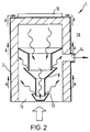
- FIG 2 this illustrates a diffusion pump according to the present invention which has been inverted through 180 degrees and generally utilising the same reference numerals as shown in Figure 1.
- the working fluid present in the wick from a reservoir at the base of the pump in normal orientation or otherwise rises through the wick material 20 by capilliary action as indicated by the arrows A to arrive at or adjacent the heater 10 where it is evaporated.
- the vaporised working fluid then passes through the chimney 8 and out via the jet stage 12 in the conventional manner. It will be evident that by using a layer of wick material 20 which covers the whole or a substantial portion of the inner surface of the outer body 2, the diffusion pump 1 can be used effectively in any orientation. This is a particularly useful attribute when evacuating small portable devices such as portable mass spectrometers which require a secondary pump to operate in any orientation.
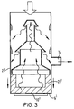
- FIG. 3 this illustrates a diffusion pump according to the present invention which as shown is in a conventional orientation.
- the wick material 20' is located over the base 6' of the body 2' as well as a portion of the inner surface of the outer body 2' adjacent the heater 10'. This will allow the diffusion pump to be transported in any orientation without the loss of working fluid or the contamination of system parts.
- This diffusion pump can be operated in the upright conventional orientation or at a considerable angle to the upright when compared with a conventional diffusion pump.
Landscapes
- Engineering & Computer Science (AREA)
- Mechanical Engineering (AREA)
- General Engineering & Computer Science (AREA)
- Compressors, Vaccum Pumps And Other Relevant Systems (AREA)
- Structures Of Non-Positive Displacement Pumps (AREA)
Abstract
A diffusion pump 1 comprises a hollow outer body 2 containing a vapour chimney 8 with at least one jet stage 12. At least a portion of the internal surface of the hollow outer body 2 is covered with a wicking material 20 for absorbing a working fluid. The use of the wicking material 20 allows the diffusion pump to be used in orientations other than the conventional upright configuration.
Description
- The present invention relates to vacuum pumps of the type known as diffusion pumps.
- Diffusion pumps are well known and widely used for the attainment of high and ultra high vacuum. When used with modern working fluids and accessories, they can produce pressures approaching 10-10 mbar. The pumps are generally incapable of exhausting directly to the atmosphere and require the use of a backing pump, commonly an oil sealed rotary vacuum pump, in conjunction with the diffusion pump itself.
- Diffusion pumps generally comprise a substantially cylindrical outer body which is cooled by, for example, coils helically wound around the outside of the body through which cooling water can be circulated or alternatively by air cooled fins attached to the outside of the body.
- Within the outer body is positioned a hollow "chimney" sitting at, or close to, the base of the outer body and which tapers (continuously or, more usually, in stages) upwardly from the base. The chimney is generally contained within the outer body and is positioned substantially concentrically therein.
- Across the top of the chimney but not in contact therewith is a top cap having a generally circular portion of somewhat larger diameter than the top of the chimney and positioned symmetrically with regard to the chimney and having a downwardly projecting annular side portion whose lower edge is somewhat beneath the upper edge of the chimney. The top cap is therefore substantially an inverted "cup shaped" component positioned about the top of the chimney with a circular or annular passageway therebetween. The top cap and the adjacent portion of the chimney defining the annular passageway is known as a 'jet stage'.
- A heater is provided in the base of the outer body and, prior to use of the pump, a working fluid is placed in the base of the body to a height above the lower edge of the chimney positioned within the body. The fluid is usually a low vapour pressure oil although some versions of diffusion pumps use mercury.
- A pump inlet is positioned in the outer body above the top cap and an outlet in the side of the body towards the base of the chimney but above the oil level. The outlet is normally connected to a backing pump as described above.
- In use of pumps of this type, the backing (rotary) pump is turned on and left running continuously, a pressure of at least 0.1 mbar being required on the exhaust side of the diffusion pump. The cooling system (water or air) for the outer body is turned on and the oil can now be heated by the heater for, for example, fifteen to twenty minutes, when it begins to boil. Hot vapour rises up the chimney and forms (aided by the taper) a relatively high oil pressure at the top of the chimney. The vapour is then urged through the passageway between the chimney and the top cap, the jet stage, to an area of much lower pressure and creates an annular vapour jet. This jet is designed to move at a velocity which is supersonic and which impinges on the inside surface of the cooled outer body where the vapour condenses and condensed oil flows down the inside wall of the outer body and returns to the oil reservoir at the base of the body.
- With the diffusion pump turned on, gas molecules being pumped in to the inlet of the diffusion pump are likely to collide with the much heavier oil vapour molecules and be provided with a velocity component which will direct the gas molecules towards the outlet of the diffusion pump where they will be subsequently removed from the diffusion pump via the backing pump. A pressure difference is thereby established across the continuously flowing vapour jet.
- A limitation of known diffusion pumps whether they be air or water cooled, is that they can operate in only one orientation; that is to say, vertically with the chimney extending vertically upwardly from the base within the hollow body, which thereby allows the condensed working fluid to drain back to the base.
- This places a limitation on the utility of the known diffusion pumps.
- It is an aim of the present invention to provide a diffusion pump which can operate efficiently or be transported in any orientation or provide a pump that can be transported in any orientation.
- According to the present invention, a diffusion pump comprises;
- a) a hollow outer body including an outlet for connection to a backing pump and an inlet for connection to a chamber to be evacuated;
- b) a vapour chimney located within the outer body and including at least one jet stage;
- c) a wick material for absorbing a working fluid extending over at least a portion of the internal surface of the outer body; and
- d) means for heating the working fluid.
- Preferably, the wick material is a sintered material.
- An embodiment of the invention will now be described, by way of example, reference being made to the Figures of the accompanying diagrammatic drawings in which:-
- Figure 1 is a cross-section through a known diffusion pump in its normal orientation ready for use;
- Figure 2 is a cross-section through a first embodiment of a diffusion pump according to the present invention; and
- Figure 3 is a cross-section through a second embodiment of a diffusion pump according to the present invention
- Referring first to Figure 1, a known
diffusion pump 1 comprises a hollowouter body 2 of generally circular cross-section, a major portion of which is provided with cooling coils 4 for circulation of cooling fluid, for example water. Thebody 2 includes abase 6 andvapour chimney 8 is positioned within theouter body 2 and extends upwardly from thebase 6. A workingfluid 7 is located in the base of thechimney 8 and, as shown, aheater 10 is located immediately below thebase 6. - As shown, the chimney is formed with a
single jet stage 12. - The
diffusion pump 1 also includes anoutlet 14 for connection to a backing vacuum pump and aninlet 16 for connection to a chamber to be evacuated. As shown, thejet stage 12 is located adjacent theinlet 16. - In use, when the
inlet 16 is attached to the chamber to be evacuated, the backing pump is turned on to reduce the pressure within thediffusion pump 1 and, if necessary, a coolant is passed through the coils 4. - Heating of the working fluid by means of the
heater 10 causes boiled vapour to rise up thechimney 8 in the general manner described earlier and to emerge through thejet stage 12 and thereafter to fall downwardly in the general direction of thebase 6 along the inner surface of theouter body 2. - As explained earlier, this known diffusion pump is very sensitive to orientation and will only operate in the orientation illustrated in Figure 1.
- In accordance with the present invention, the hollow
outer body 2 of thediffusion pump 1 is provided on its inside surface with a layout of wick material 20 (see Figure 2) which will absorb the working fluid. - Referring now to Figure 2, this illustrates a diffusion pump according to the present invention which has been inverted through 180 degrees and generally utilising the same reference numerals as shown in Figure 1. In use, the working fluid present in the wick from a reservoir at the base of the pump in normal orientation or otherwise rises through the
wick material 20 by capilliary action as indicated by the arrows A to arrive at or adjacent theheater 10 where it is evaporated. - The vaporised working fluid then passes through the
chimney 8 and out via thejet stage 12 in the conventional manner. It will be evident that by using a layer ofwick material 20 which covers the whole or a substantial portion of the inner surface of theouter body 2, thediffusion pump 1 can be used effectively in any orientation. This is a particularly useful attribute when evacuating small portable devices such as portable mass spectrometers which require a secondary pump to operate in any orientation. - Referring now to Figure 3, this illustrates a diffusion pump according to the present invention which as shown is in a conventional orientation. In this embodiment the wick material 20' is located over the base 6' of the body 2' as well as a portion of the inner surface of the outer body 2' adjacent the heater 10'. This will allow the diffusion pump to be transported in any orientation without the loss of working fluid or the contamination of system parts. This diffusion pump can be operated in the upright conventional orientation or at a considerable angle to the upright when compared with a conventional diffusion pump.
Claims (3)
- A diffusion pump 1 comprising a hollow outer body 2 including an outlet 14 for connection to a backing pump and an inlet 16 for connection to a chamber to be evacuated, a vapour chimney 8 located within the outer body 2 including at least one jet stage 12 and means 10 for healing a working fluid, characterised by a wick material 20 for absorbing the working fluid extending over at least a portion of the internal surface of the outer body 2.
- A diffusion pump as claimed in Claim 1, in which the wick material 20 extends over a base 6 of the hollow outer body 2.
- A diffusion pump as claimed in Claim 1 or 2, in which the wick material 20 is a sintered material.
Applications Claiming Priority (2)
| Application Number | Priority Date | Filing Date | Title |
|---|---|---|---|
| GBGB9609467.7A GB9609467D0 (en) | 1996-05-07 | 1996-05-07 | Improvements in diffusion pumps |
| GB9609467 | 1996-05-07 |
Publications (2)
| Publication Number | Publication Date |
|---|---|
| EP0806572A2 true EP0806572A2 (en) | 1997-11-12 |
| EP0806572A3 EP0806572A3 (en) | 1998-06-17 |
Family
ID=10793279
Family Applications (1)
| Application Number | Title | Priority Date | Filing Date |
|---|---|---|---|
| EP97302923A Withdrawn EP0806572A3 (en) | 1996-05-07 | 1997-04-29 | Improvements in diffusion pumps |
Country Status (3)
| Country | Link |
|---|---|
| EP (1) | EP0806572A3 (en) |
| JP (1) | JPH1073100A (en) |
| GB (1) | GB9609467D0 (en) |
Family Cites Families (3)
| Publication number | Priority date | Publication date | Assignee | Title |
|---|---|---|---|---|
| GB1448750A (en) * | 1973-12-28 | 1976-09-08 | Boc International Ltd | Vacuum vapour pumps |
| SU985415A1 (en) * | 1980-11-05 | 1982-12-30 | Предприятие П/Я А-3634 | Cooled trap |
| SU1576737A1 (en) * | 1988-09-27 | 1990-07-07 | Предприятие П/Я А-3605 | Adsorbing trap |
-
1996
- 1996-05-07 GB GBGB9609467.7A patent/GB9609467D0/en active Pending
-
1997
- 1997-04-29 EP EP97302923A patent/EP0806572A3/en not_active Withdrawn
- 1997-05-07 JP JP15277497A patent/JPH1073100A/en active Pending
Also Published As
| Publication number | Publication date |
|---|---|
| GB9609467D0 (en) | 1996-07-10 |
| EP0806572A3 (en) | 1998-06-17 |
| JPH1073100A (en) | 1998-03-17 |
Similar Documents
| Publication | Publication Date | Title |
|---|---|---|
| US5894887A (en) | Ceramic dome temperature control using heat pipe structure and method | |
| CN109073301B (en) | Heat pump with heterogeneous gas accumulation chamber, method for operating a heat pump and method for manufacturing a heat pump | |
| EP0806572A2 (en) | Improvements in diffusion pumps | |
| US4343292A (en) | Vapor jacketed cooking vessel | |
| EP0730096B1 (en) | Improvements in diffusion pumps | |
| US5993166A (en) | Diffusion pumps having an integrated reservoir for the working fluid | |
| US5913662A (en) | Diffusion pump with two inlets and two stage pumping capability | |
| JP2737378B2 (en) | Refrigerant degassing equipment | |
| US2305947A (en) | Diffusion pump | |
| CN217796219U (en) | A vacuum quantitative concentration equipment | |
| US6915842B2 (en) | Heat-transfer device | |
| US3117714A (en) | Gas or vapour condensers | |
| US2923458A (en) | Diffusion pumps | |
| JPH1182399A (en) | Diffusion pump | |
| JP3332429B2 (en) | Double tank type cryogenic fluid drainage tank | |
| JPS56135987A (en) | Gas laser device | |
| US20030210986A1 (en) | Diffusion pumps | |
| JPH0131285Y2 (en) | ||
| JPH0238023Y2 (en) | ||
| JPH05223271A (en) | Temperature difference type pump | |
| SU954602A1 (en) | Cryogenic vacuum pump | |
| JPS6411323B2 (en) | ||
| SU1108255A1 (en) | Cryogenic trap | |
| US2999363A (en) | Double-walled pipe for liquified gas | |
| JPS5627891A (en) | Radiator |
Legal Events
| Date | Code | Title | Description |
|---|---|---|---|
| PUAI | Public reference made under article 153(3) epc to a published international application that has entered the european phase |
Free format text: ORIGINAL CODE: 0009012 |
|
| AK | Designated contracting states |
Kind code of ref document: A2 Designated state(s): CH DE FR GB IT LI |
|
| PUAL | Search report despatched |
Free format text: ORIGINAL CODE: 0009013 |
|
| AK | Designated contracting states |
Kind code of ref document: A3 Designated state(s): CH DE FR GB IT LI |
|
| 17P | Request for examination filed |
Effective date: 19980701 |
|
| STAA | Information on the status of an ep patent application or granted ep patent |
Free format text: STATUS: THE APPLICATION IS DEEMED TO BE WITHDRAWN |
|
| 18D | Application deemed to be withdrawn |
Effective date: 20001101 |