EP0806575A1 - Dispositif de fixation - Google Patents
Dispositif de fixation Download PDFInfo
- Publication number
- EP0806575A1 EP0806575A1 EP97106667A EP97106667A EP0806575A1 EP 0806575 A1 EP0806575 A1 EP 0806575A1 EP 97106667 A EP97106667 A EP 97106667A EP 97106667 A EP97106667 A EP 97106667A EP 0806575 A1 EP0806575 A1 EP 0806575A1
- Authority
- EP
- European Patent Office
- Prior art keywords
- component
- holes
- clamping
- groove
- elements
- Prior art date
- Legal status (The legal status is an assumption and is not a legal conclusion. Google has not performed a legal analysis and makes no representation as to the accuracy of the status listed.)
- Granted
Links
- 125000006850 spacer group Chemical group 0.000 claims description 16
- 230000000295 complement effect Effects 0.000 claims description 4
- 210000000078 claw Anatomy 0.000 claims description 2
- 238000010276 construction Methods 0.000 description 5
- 229910000831 Steel Inorganic materials 0.000 description 3
- 230000000712 assembly Effects 0.000 description 3
- 238000000429 assembly Methods 0.000 description 3
- 239000010959 steel Substances 0.000 description 3
- XAGFODPZIPBFFR-UHFFFAOYSA-N aluminium Chemical compound [Al] XAGFODPZIPBFFR-UHFFFAOYSA-N 0.000 description 2
- 229910052782 aluminium Inorganic materials 0.000 description 2
- 238000005253 cladding Methods 0.000 description 1
- 238000009434 installation Methods 0.000 description 1
- 230000003993 interaction Effects 0.000 description 1
- 230000000284 resting effect Effects 0.000 description 1
- 239000002344 surface layer Substances 0.000 description 1
Images
Classifications
-
- H—ELECTRICITY
- H02—GENERATION; CONVERSION OR DISTRIBUTION OF ELECTRIC POWER
- H02B—BOARDS, SUBSTATIONS OR SWITCHING ARRANGEMENTS FOR THE SUPPLY OR DISTRIBUTION OF ELECTRIC POWER
- H02B1/00—Frameworks, boards, panels, desks, casings; Details of substations or switching arrangements
- H02B1/26—Casings; Parts thereof or accessories therefor
- H02B1/30—Cabinet-type casings; Parts thereof or accessories therefor
- H02B1/32—Mounting of devices therein
-
- F—MECHANICAL ENGINEERING; LIGHTING; HEATING; WEAPONS; BLASTING
- F16—ENGINEERING ELEMENTS AND UNITS; GENERAL MEASURES FOR PRODUCING AND MAINTAINING EFFECTIVE FUNCTIONING OF MACHINES OR INSTALLATIONS; THERMAL INSULATION IN GENERAL
- F16B—DEVICES FOR FASTENING OR SECURING CONSTRUCTIONAL ELEMENTS OR MACHINE PARTS TOGETHER, e.g. NAILS, BOLTS, CIRCLIPS, CLAMPS, CLIPS OR WEDGES; JOINTS OR JOINTING
- F16B5/00—Joining sheets or plates, e.g. panels, to one another or to strips or bars parallel to them
- F16B5/07—Joining sheets or plates, e.g. panels, to one another or to strips or bars parallel to them by means of multiple interengaging protrusions on the surfaces, e.g. hooks, coils
-
- F—MECHANICAL ENGINEERING; LIGHTING; HEATING; WEAPONS; BLASTING
- F16—ENGINEERING ELEMENTS AND UNITS; GENERAL MEASURES FOR PRODUCING AND MAINTAINING EFFECTIVE FUNCTIONING OF MACHINES OR INSTALLATIONS; THERMAL INSULATION IN GENERAL
- F16B—DEVICES FOR FASTENING OR SECURING CONSTRUCTIONAL ELEMENTS OR MACHINE PARTS TOGETHER, e.g. NAILS, BOLTS, CIRCLIPS, CLAMPS, CLIPS OR WEDGES; JOINTS OR JOINTING
- F16B7/00—Connections of rods or tubes, e.g. of non-circular section, mutually, including resilient connections
- F16B7/22—Connections of rods or tubes, e.g. of non-circular section, mutually, including resilient connections using hooks or like elements
-
- F—MECHANICAL ENGINEERING; LIGHTING; HEATING; WEAPONS; BLASTING
- F16—ENGINEERING ELEMENTS AND UNITS; GENERAL MEASURES FOR PRODUCING AND MAINTAINING EFFECTIVE FUNCTIONING OF MACHINES OR INSTALLATIONS; THERMAL INSULATION IN GENERAL
- F16B—DEVICES FOR FASTENING OR SECURING CONSTRUCTIONAL ELEMENTS OR MACHINE PARTS TOGETHER, e.g. NAILS, BOLTS, CIRCLIPS, CLAMPS, CLIPS OR WEDGES; JOINTS OR JOINTING
- F16B2200/00—Constructional details of connections not covered for in other groups of this subclass
- F16B2200/69—Redundant disconnection blocking means
Definitions
- the invention relates to a fastening arrangement according to the preamble of claim 1.
- housings and cabinets for example equipment cabinets based on the 19 "system, vertically and horizontally arranged components, usually cut to length, are connected to form a frame structure and provided with cladding parts.
- Rail-like components for example telescopic rails, are arranged to accommodate printer and keyboard modules and similar devices or electrical or electronic assemblies.
- fastening has generally been carried out using fastening screws which interact with appropriately designed nuts in the bores or T-slots of the spar profiles.
- the assembly of the rail-like components, flat sheets and similar components takes up a lot of time, which is disadvantageously noticeable when building and converting an equipment cabinet, a frame and the like.
- the object of the invention is to create a fastening arrangement which, with an extraordinarily simple structure, enables a structural or component to be fastened to another component quickly.
- the invention is based on the basic idea of connecting two components to one another via a clamping bracket and to achieve the clamping bracket by means of clamping elements which are integrated in at least one component and are preferably formed on the edge.
- the clamping elements and spacer elements interact with a groove, in particular a T-groove, or with a row of holes which has alternating openings, preferably elongated holes and round holes, and are designed such that a rear grip, in particular at the edges of the elongated holes, and a System, preferably in the area of the round holes, or in the groove is reached.
- Clamping of the component to be fastened is achieved via the engaging clamping elements and the spacing elements resting on or in openings, which, in particular when the component to be fastened oppositely jamming, does not require any additional fastening elements for secure and stable mounting.
- Another advantage is that an extremely rapid fixing is possible, since only the edge integrally formed clamping and spacer elements inserted in the respective row of holes or T-groove or brought into contact and o clamped by a subsequent pivoting about the 90th A structural part clamped on one side still has a pivoting range in the fastening position, which is approximately up to 10 o . As soon as a component is jammed with rows of holes in rows of holes and / or T-slots in the adjacent profiles, there is no longer any such play, but safe and stable jamming and clamping between the two profiles.
- the fastening arrangement it is particularly advantageous to connect at least one component of the fastening arrangement according to the invention to a further component or structural part, for example a telescopic rail, and thereby a particularly efficient fastening of the telescopic rail to a component and in particular to a profile spar which has at least one row of holes or a groove or also has at least one row of holes and at least one T-groove.
- the structural part to be fastened for example the telescopic rail, connects, in particular screwed, the component of the fastening arrangement that has the clamping and holding elements.
- the telescopic rail or also a side wall or other assemblies can be fixed to the profile spar particularly quickly and without further aids.
- the component to be fastened lies almost on the surface that has the row of holes or groove and thus runs almost at right angles to the profile surface.
- the clamping elements are angled and hook-like for a grip on recesses, holes, bores and the like, in particular on the elongated holes.
- the spacing or positioning elements are small, e.g. with an angle of inclination of approximately 10 degrees, bent and rounded at the ends for an installation in the round holes.
- a rear grip can also be realized in the round holes and a positive fit in the elongated holes.
- the interaction of the engaging clamping hooks and the adjoining spacer elements or the spacer elements accommodated in the round holes is essential for jamming the component to be fastened.
- An alternating arrangement of the clamping hooks and spacer elements or of the elongated holes and round holes is particularly advantageous for a press fit and a positive and non-positive connection of two components, the latter being designed in particular as circular bores.
- a preferred embodiment of the quick fastening according to the invention provides two round holes which are delimited by an upper and a lower elongated hole.
- two spacer elements are delimited by an upper and lower clamping hook on an associated component to be fastened.
- the grid dimensions of the holes in the row of holes and the clamping and spacing elements are matched to one another.
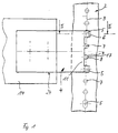
- first component 2 which is a vertical profile spar of a device cabinet
- second component 4 which serves as a fastening element for a construction element 14 to be fastened, for example for a telescopic rail, and with the component 2 is to be connected.
- the vertical profile spar 2 which is made, for example, of aluminum or steel, has a row of holes 3 composed of elongated holes 5 and round holes 7 arranged in a grid, two round holes 7 being formed between an upper and an elongated hole 5.
- the round holes 7 are circular holes.
- a rail-like fastening element is fastened to the profile spar 2 as a second component 4, to which the construction element 14 shown only as a cutout is fastened, for example by means of fastening screws (not shown), and which has an edge region 11 with integrated clamping elements 6 and spacing elements 8. 1 shows that the clamping elements 6 and spacers 8 of the fastening element 4 are complementary to the two different types of holes 5, 7 of the vertical profile spar 2 and have the same pitch as the holes 5, 7 of the vertical profile 2.
- Clamping hooks 6 are formed as clamping elements, which are designed to be angled twice for engaging behind the elongated hole 5 and for contacting a rear edge region 15 of the elongated hole 5 (see also FIGS. 2 and 3).
- tongue-shaped spacer elements 8 are formed which, together with the clamping hooks 6, cause a clamping holder of the edge region 11 due to their arrangement and angling or beveling.
- the component 4 of the fastening arrangement according to the invention which serves as a fastening element for further components and structural elements 14, is produced from a steel sheet with a wall thickness of 2.0 mm.
- the wall thickness of the first component for example a vertical spar, can be 1.9 mm when using an aluminum profile and 1.5 mm when using a steel profile.
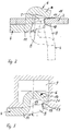
- FIG. 2 From Fig. 2 the clamp bracket and the quick fastener can be seen.
- the dash-dotted lines represent a fastening element as a second component 4 in a position in which the clamping elements 6 have not yet or only partially been inserted into the elongated holes 5 of the profile spar as the first component 2 and the spacer elements 8 have not yet been end-positioned, but on the outer edge of the round holes 7 are supported.
- the clamping position of the second component 4 to be fastened and the arrangement of a clamping element 6 and a spacing element 8 in the clamping position are shown with solid lines and dashed lines.
- the second component 4 has integrally arranged clamping hooks 6 and spacing elements 8 on an edge region 11.
- the clamping hooks 6 are bent at right angles at the edge region 11 and provided with a clamping leg 16 which is inclined inwards and ensures the rear grip and an abutment on a rear edge region 15 of an elongated hole 5.
- the vertical dimensions of the clamping hook 6 are coordinated with those of the elongated hole 5.
- a spacing element 8 below the clamping hook 6 lies with little engagement in the round hole 7 and is supported with an end face 18 on an inner edge region 17 of the round hole 7.
- the spacer 8 is slightly bevelled on the edge region 11.
- An angle of inclination ⁇ can be approximately 10 degrees.
- FIG. 3 Analogously to FIG. 2, a clamp holder of a fastening element as component 4 with an edge region 11 is shown in FIG. 3. Identical features have been given the same features.
- the second component 4 which is provided for fastening a construction element 14 shown only in FIG. 1, is not fastened in a row of holes, but in a T-groove 9 of a first component 2.
- the first component 2 has at least one T-groove and at the same time at least one row of holes 3.
- a clamping leg 16 of the clamping hook 6 lies against an inner side 21 of a groove leg and is guided through a slot 19 of the T-groove 9 for this purpose.
- the spacer element 8 lies against an inner edge region 17 of the slot 19 of the T-groove 9.
- the spacer elements 8 are substantially shorter than the clamping hook 6 and, by means of a defined abutment or support, ensure an exact arrangement and positioning of the clamping elements 6 in a row of holes 3 or a T-slot 9.
- the clamping hook 6 can be provided on the clamping leg 16 and in particular on its end region with small, pointed projections which claw into the surface layer.
- the fastening arrangement according to the invention with a first and a second component can be used for fast and easy-to-assemble fastening of various assemblies and structural parts and is particularly suitable for fastening rail-like components, such as telescopic rails, in a cabinet or frame system.
Landscapes
- Engineering & Computer Science (AREA)
- General Engineering & Computer Science (AREA)
- Mechanical Engineering (AREA)
- Power Engineering (AREA)
- Connection Of Plates (AREA)
- Materials For Medical Uses (AREA)
- Dowels (AREA)
- Orthopedics, Nursing, And Contraception (AREA)
- Assembled Shelves (AREA)
- Rod-Shaped Construction Members (AREA)
- Furniture Connections (AREA)
- Mutual Connection Of Rods And Tubes (AREA)
- Clamps And Clips (AREA)
Applications Claiming Priority (2)
| Application Number | Priority Date | Filing Date | Title |
|---|---|---|---|
| DE19618127 | 1996-05-06 | ||
| DE19618127A DE19618127C1 (de) | 1996-05-06 | 1996-05-06 | Befestigungsanordnung |
Publications (2)
| Publication Number | Publication Date |
|---|---|
| EP0806575A1 true EP0806575A1 (fr) | 1997-11-12 |
| EP0806575B1 EP0806575B1 (fr) | 1999-12-01 |
Family
ID=7793467
Family Applications (1)
| Application Number | Title | Priority Date | Filing Date |
|---|---|---|---|
| EP97106667A Expired - Lifetime EP0806575B1 (fr) | 1996-05-06 | 1997-04-22 | Dispositif de fixation |
Country Status (5)
| Country | Link |
|---|---|
| US (1) | US5931426A (fr) |
| EP (1) | EP0806575B1 (fr) |
| JP (1) | JPH1057159A (fr) |
| AT (1) | ATE187229T1 (fr) |
| DE (2) | DE19618127C1 (fr) |
Families Citing this family (11)
| Publication number | Priority date | Publication date | Assignee | Title |
|---|---|---|---|---|
| US6253898B1 (en) * | 1998-07-02 | 2001-07-03 | O'brien Daniel F. | Equipment loading plank |
| TW453621U (en) * | 1999-06-08 | 2001-09-01 | Hon Hai Prec Ind Co Ltd | Structure for combining stopping sheet and carrying seat |
| DE10007470C2 (de) * | 2000-02-18 | 2002-06-20 | Rittal Gmbh & Co Kg | Schaltschrank |
| DE10119994B4 (de) * | 2001-04-23 | 2009-04-09 | Dorma Gmbh + Co. Kg | Klemmhalter |
| US6732866B2 (en) * | 2002-04-24 | 2004-05-11 | East Industries, Ltd. | Combination shelf and display unit |
| US7029143B2 (en) * | 2002-10-22 | 2006-04-18 | Ceilings Plus | Light cove |
| WO2004100473A2 (fr) * | 2003-04-30 | 2004-11-18 | Analog Devices, Inc. | Isolateurs de signal utilisant des micro-transformateurs |
| US8713889B2 (en) * | 2011-01-14 | 2014-05-06 | Ronald Buttner | Anchor bracket and method of mounting anchor bracket |
| US20120260549A1 (en) * | 2011-04-14 | 2012-10-18 | Nielsen Bainbridge | Picture frame wall bracket |
| CN103580592A (zh) * | 2012-08-09 | 2014-02-12 | 富昱能源科技(昆山)有限公司 | 支架结构 |
| CN108061088A (zh) * | 2017-12-12 | 2018-05-22 | 无锡优耐特能源科技有限公司 | 一种支架连接件 |
Citations (5)
| Publication number | Priority date | Publication date | Assignee | Title |
|---|---|---|---|---|
| DE2161889A1 (de) * | 1971-12-14 | 1973-06-20 | Geb Posselt Ursula Schaefer | Steck- und riegelverbindung |
| DE9110389U1 (de) * | 1991-08-22 | 1992-12-17 | Klöckner-Moeller GmbH, 5300 Bonn | Tragvorrichtung für Schalt- und Steuergeräte |
| EP0534578A1 (fr) * | 1991-09-26 | 1993-03-31 | Siemens Aktiengesellschaft | Dispositif de support pour appareils électriques |
| EP0557213A1 (fr) * | 1992-02-21 | 1993-08-25 | Schneider Electric Sa | Dispositif pour assembler l'une contre l'autre deux plaques rigides |
| EP0668644A1 (fr) * | 1994-02-17 | 1995-08-23 | Schneider Electric Sa | Dispositif d'installation électrique à platine support équipé d'une bride de raccordement |
Family Cites Families (14)
| Publication number | Priority date | Publication date | Assignee | Title |
|---|---|---|---|---|
| US3248079A (en) * | 1963-12-30 | 1966-04-26 | Clark Equipment Co | Angularly adjustable shelf bracket |
| US3272345A (en) * | 1965-01-11 | 1966-09-13 | Brad Mar Corp | Cloth bolt holder and rack |
| US3353684A (en) * | 1965-10-22 | 1967-11-21 | Chesley Ind Inc | Shelf structure |
| GB1222488A (en) * | 1969-09-11 | 1971-02-17 | Basil Zachariou | Improvements in shelving assemblies |
| US4204480A (en) * | 1975-07-30 | 1980-05-27 | The Mead Corporation | Shelving system |
| US4378925A (en) * | 1981-03-10 | 1983-04-05 | Lingo Manufacturing Company | T-Bracket shelf assembly |
| ZA822552B (en) * | 1981-04-22 | 1983-03-30 | Dexion Comino Int Ltd | Framework connection means |
| US4553725A (en) * | 1982-02-25 | 1985-11-19 | Vargo William R | Steel shelving mounting clip and shelving structure |
| US5277393A (en) * | 1989-03-10 | 1994-01-11 | Mccalla/Lackey Corporation | Shelving unit |
| US5265740A (en) * | 1991-12-23 | 1993-11-30 | The Winsford Corporation | Adjustable storage apparatus for computer media |
| FR2720792B1 (fr) * | 1993-12-23 | 1996-07-12 | Alplast Sarl | Dispositif pour la fixation d'ustensiles et d'outils sur un support perforé. |
| US5477971A (en) * | 1994-04-29 | 1995-12-26 | L&P Property Management Company | Gondola rack modular stacking system |
| US5538213A (en) * | 1994-09-21 | 1996-07-23 | Brown Office Systems, Inc. | Bracket for shelving, furniture and the like |
| US5575444A (en) * | 1995-03-16 | 1996-11-19 | Otema; Martin | Adjustable shelf bracket |
-
1996
- 1996-05-06 DE DE19618127A patent/DE19618127C1/de not_active Expired - Fee Related
-
1997
- 1997-04-22 DE DE59700784T patent/DE59700784D1/de not_active Expired - Fee Related
- 1997-04-22 AT AT97106667T patent/ATE187229T1/de not_active IP Right Cessation
- 1997-04-22 EP EP97106667A patent/EP0806575B1/fr not_active Expired - Lifetime
- 1997-05-06 JP JP9115853A patent/JPH1057159A/ja not_active Withdrawn
- 1997-05-06 US US08/851,890 patent/US5931426A/en not_active Expired - Fee Related
Patent Citations (5)
| Publication number | Priority date | Publication date | Assignee | Title |
|---|---|---|---|---|
| DE2161889A1 (de) * | 1971-12-14 | 1973-06-20 | Geb Posselt Ursula Schaefer | Steck- und riegelverbindung |
| DE9110389U1 (de) * | 1991-08-22 | 1992-12-17 | Klöckner-Moeller GmbH, 5300 Bonn | Tragvorrichtung für Schalt- und Steuergeräte |
| EP0534578A1 (fr) * | 1991-09-26 | 1993-03-31 | Siemens Aktiengesellschaft | Dispositif de support pour appareils électriques |
| EP0557213A1 (fr) * | 1992-02-21 | 1993-08-25 | Schneider Electric Sa | Dispositif pour assembler l'une contre l'autre deux plaques rigides |
| EP0668644A1 (fr) * | 1994-02-17 | 1995-08-23 | Schneider Electric Sa | Dispositif d'installation électrique à platine support équipé d'une bride de raccordement |
Also Published As
| Publication number | Publication date |
|---|---|
| DE59700784D1 (de) | 2000-01-05 |
| EP0806575B1 (fr) | 1999-12-01 |
| US5931426A (en) | 1999-08-03 |
| DE19618127C1 (de) | 1997-10-09 |
| JPH1057159A (ja) | 1998-03-03 |
| ATE187229T1 (de) | 1999-12-15 |
Similar Documents
| Publication | Publication Date | Title |
|---|---|---|
| EP3763035B1 (fr) | Borne d'extrémité pour fixer un module photovoltaïque doté d'un cadre | |
| EP0452256B1 (fr) | Connexion angulaire de deux profilés avec prolongation en C utilisant un connecteur et un élément en angle pour le montage de ladite connexion | |
| EP0686316B1 (fr) | Armoire | |
| EP0602314A1 (fr) | Dispositif pour assurer le maintien en place d'éléments de fixation dans des logements au moyen de l'élasticité de ressorts | |
| EP1070923A2 (fr) | Dispositif pour la fixation de modules solaires | |
| DE3513384A1 (de) | Profilsystem zum bau von montageeinrichtungen, stuetzkonstruktionen und transportbaendern | |
| DE102007018212B4 (de) | Befestigungseinrichtung für an einem Gestellaufbau anzuordnende Rahmenbauteile, insbesondere Solarmodule | |
| EP0806575B1 (fr) | Dispositif de fixation | |
| EP1840315B1 (fr) | Construction de cadre | |
| DE2164991A1 (de) | Ankerschiene | |
| EP0579578A1 (fr) | Plaque de raccordement à une structure de support | |
| EP0935500B1 (fr) | Paroi de cabine pour chaine de vernissage | |
| EP3721100B1 (fr) | Ensemble de liaison | |
| EP0335857B1 (fr) | Jonction entre au moins deux profilés ou plaques de métal profilées | |
| DE69925404T2 (de) | Metallische Verbindungsvorrichtung und Beschlagteile dafür | |
| DE102009017164A1 (de) | Haltevorrichtung | |
| DE2707718A1 (de) | Aus platten zusammengesetzte unterdecke | |
| WO2006092156A1 (fr) | Element paroi | |
| DE8328123U1 (de) | Haltevorrichtung | |
| EP0593871B1 (fr) | Agencement lumineux à armatures lumineuses disposées l'une derrière l'autre ou cÔte-à-cÔte | |
| DE9405831U1 (de) | Halteelement für Fachböden | |
| EP0542007B1 (fr) | Dispositif de liaison de profilés de construction et/ou de pièces semblable, spécialement pour des systèmes d'assemblage flexibles | |
| DE4301634C2 (de) | Rahmengestell aus Rahmenschenkeln für einen Schaltschrank | |
| EP3720790B1 (fr) | Appareil de transport | |
| DE7230142U (de) | Anordnung für elektronische Einschubsysteme |
Legal Events
| Date | Code | Title | Description |
|---|---|---|---|
| PUAI | Public reference made under article 153(3) epc to a published international application that has entered the european phase |
Free format text: ORIGINAL CODE: 0009012 |
|
| AK | Designated contracting states |
Kind code of ref document: A1 Designated state(s): AT BE CH DE DK ES FR GB IT LI NL SE |
|
| 17P | Request for examination filed |
Effective date: 19971013 |
|
| 17Q | First examination report despatched |
Effective date: 19980702 |
|
| GRAG | Despatch of communication of intention to grant |
Free format text: ORIGINAL CODE: EPIDOS AGRA |
|
| GRAG | Despatch of communication of intention to grant |
Free format text: ORIGINAL CODE: EPIDOS AGRA |
|
| GRAH | Despatch of communication of intention to grant a patent |
Free format text: ORIGINAL CODE: EPIDOS IGRA |
|
| GRAH | Despatch of communication of intention to grant a patent |
Free format text: ORIGINAL CODE: EPIDOS IGRA |
|
| GRAA | (expected) grant |
Free format text: ORIGINAL CODE: 0009210 |
|
| AK | Designated contracting states |
Kind code of ref document: B1 Designated state(s): AT BE CH DE DK ES FR GB IT LI NL SE |
|
| PG25 | Lapsed in a contracting state [announced via postgrant information from national office to epo] |
Ref country code: SE Free format text: THE PATENT HAS BEEN ANNULLED BY A DECISION OF A NATIONAL AUTHORITY Effective date: 19991201 Ref country code: NL Free format text: LAPSE BECAUSE OF FAILURE TO SUBMIT A TRANSLATION OF THE DESCRIPTION OR TO PAY THE FEE WITHIN THE PRESCRIBED TIME-LIMIT Effective date: 19991201 Ref country code: IT Free format text: LAPSE BECAUSE OF FAILURE TO SUBMIT A TRANSLATION OF THE DESCRIPTION OR TO PAY THE FEE WITHIN THE PRESCRIBED TIME-LIMIT;WARNING: LAPSES OF ITALIAN PATENTS WITH EFFECTIVE DATE BEFORE 2007 MAY HAVE OCCURRED AT ANY TIME BEFORE 2007. THE CORRECT EFFECTIVE DATE MAY BE DIFFERENT FROM THE ONE RECORDED. Effective date: 19991201 Ref country code: GB Free format text: LAPSE BECAUSE OF FAILURE TO SUBMIT A TRANSLATION OF THE DESCRIPTION OR TO PAY THE FEE WITHIN THE PRESCRIBED TIME-LIMIT Effective date: 19991201 Ref country code: FR Free format text: LAPSE BECAUSE OF FAILURE TO SUBMIT A TRANSLATION OF THE DESCRIPTION OR TO PAY THE FEE WITHIN THE PRESCRIBED TIME-LIMIT Effective date: 19991201 Ref country code: ES Free format text: THE PATENT HAS BEEN ANNULLED BY A DECISION OF A NATIONAL AUTHORITY Effective date: 19991201 |
|
| REF | Corresponds to: |
Ref document number: 187229 Country of ref document: AT Date of ref document: 19991215 Kind code of ref document: T |
|
| REG | Reference to a national code |
Ref country code: CH Ref legal event code: EP |
|
| REF | Corresponds to: |
Ref document number: 59700784 Country of ref document: DE Date of ref document: 20000105 |
|
| PG25 | Lapsed in a contracting state [announced via postgrant information from national office to epo] |
Ref country code: DK Free format text: LAPSE BECAUSE OF FAILURE TO SUBMIT A TRANSLATION OF THE DESCRIPTION OR TO PAY THE FEE WITHIN THE PRESCRIBED TIME-LIMIT Effective date: 20000301 |
|
| PG25 | Lapsed in a contracting state [announced via postgrant information from national office to epo] |
Ref country code: AT Free format text: LAPSE BECAUSE OF NON-PAYMENT OF DUE FEES Effective date: 20000422 |
|
| EN | Fr: translation not filed | ||
| PG25 | Lapsed in a contracting state [announced via postgrant information from national office to epo] |
Ref country code: BE Free format text: LAPSE BECAUSE OF NON-PAYMENT OF DUE FEES Effective date: 20000430 |
|
| NLV1 | Nl: lapsed or annulled due to failure to fulfill the requirements of art. 29p and 29m of the patents act | ||
| GBV | Gb: ep patent (uk) treated as always having been void in accordance with gb section 77(7)/1977 [no translation filed] |
Effective date: 19991201 |
|
| PLBE | No opposition filed within time limit |
Free format text: ORIGINAL CODE: 0009261 |
|
| STAA | Information on the status of an ep patent application or granted ep patent |
Free format text: STATUS: NO OPPOSITION FILED WITHIN TIME LIMIT |
|
| BERE | Be: lapsed |
Owner name: KNURR-MECHANIK FUR DIE ELEKTRONIK A.G. Effective date: 20000430 |
|
| 26N | No opposition filed | ||
| PG25 | Lapsed in a contracting state [announced via postgrant information from national office to epo] |
Ref country code: LI Free format text: LAPSE BECAUSE OF NON-PAYMENT OF DUE FEES Effective date: 20010521 Ref country code: CH Free format text: LAPSE BECAUSE OF NON-PAYMENT OF DUE FEES Effective date: 20010521 |
|
| REG | Reference to a national code |
Ref country code: CH Ref legal event code: PL |
|
| PGFP | Annual fee paid to national office [announced via postgrant information from national office to epo] |
Ref country code: DE Payment date: 20020429 Year of fee payment: 6 |
|
| PG25 | Lapsed in a contracting state [announced via postgrant information from national office to epo] |
Ref country code: DE Free format text: LAPSE BECAUSE OF NON-PAYMENT OF DUE FEES Effective date: 20031101 |