EP0806593B1 - Dispositif de verrouillage de la marche arrière d'une boíte de vitesses à plusieurs rapports - Google Patents
Dispositif de verrouillage de la marche arrière d'une boíte de vitesses à plusieurs rapports Download PDFInfo
- Publication number
- EP0806593B1 EP0806593B1 EP97107091A EP97107091A EP0806593B1 EP 0806593 B1 EP0806593 B1 EP 0806593B1 EP 97107091 A EP97107091 A EP 97107091A EP 97107091 A EP97107091 A EP 97107091A EP 0806593 B1 EP0806593 B1 EP 0806593B1
- Authority
- EP
- European Patent Office
- Prior art keywords
- shift
- reverse gear
- finger
- lockout
- locking
- Prior art date
- Legal status (The legal status is an assumption and is not a legal conclusion. Google has not performed a legal analysis and makes no representation as to the accuracy of the status listed.)
- Expired - Lifetime
Links
- 230000003213 activating effect Effects 0.000 claims 1
- 230000005540 biological transmission Effects 0.000 description 2
- 230000002028 premature Effects 0.000 description 1
Images

Classifications
-
- F—MECHANICAL ENGINEERING; LIGHTING; HEATING; WEAPONS; BLASTING
- F16—ENGINEERING ELEMENTS AND UNITS; GENERAL MEASURES FOR PRODUCING AND MAINTAINING EFFECTIVE FUNCTIONING OF MACHINES OR INSTALLATIONS; THERMAL INSULATION IN GENERAL
- F16H—GEARING
- F16H61/00—Control functions within control units of change-speed- or reversing-gearings for conveying rotary motion ; Control of exclusively fluid gearing, friction gearing, gearings with endless flexible members or other particular types of gearing
- F16H61/18—Preventing unintentional or unsafe shift, e.g. preventing manual shift from highest gear to reverse gear
-
- F—MECHANICAL ENGINEERING; LIGHTING; HEATING; WEAPONS; BLASTING
- F16—ENGINEERING ELEMENTS AND UNITS; GENERAL MEASURES FOR PRODUCING AND MAINTAINING EFFECTIVE FUNCTIONING OF MACHINES OR INSTALLATIONS; THERMAL INSULATION IN GENERAL
- F16H—GEARING
- F16H63/00—Control outputs from the control unit to change-speed- or reversing-gearings for conveying rotary motion or to other devices than the final output mechanism
- F16H63/02—Final output mechanisms therefor; Actuating means for the final output mechanisms
- F16H63/30—Constructional features of the final output mechanisms
- F16H63/302—Final output mechanisms for reversing
-
- F—MECHANICAL ENGINEERING; LIGHTING; HEATING; WEAPONS; BLASTING
- F16—ENGINEERING ELEMENTS AND UNITS; GENERAL MEASURES FOR PRODUCING AND MAINTAINING EFFECTIVE FUNCTIONING OF MACHINES OR INSTALLATIONS; THERMAL INSULATION IN GENERAL
- F16H—GEARING
- F16H63/00—Control outputs from the control unit to change-speed- or reversing-gearings for conveying rotary motion or to other devices than the final output mechanism
- F16H63/02—Final output mechanisms therefor; Actuating means for the final output mechanisms
- F16H63/08—Multiple final output mechanisms being moved by a single common final actuating mechanism
- F16H63/20—Multiple final output mechanisms being moved by a single common final actuating mechanism with preselection and subsequent movement of each final output mechanism by movement of the final actuating mechanism in two different ways, e.g. guided by a shift gate
- F16H2063/208—Multiple final output mechanisms being moved by a single common final actuating mechanism with preselection and subsequent movement of each final output mechanism by movement of the final actuating mechanism in two different ways, e.g. guided by a shift gate using two or more selecting fingers
Definitions
- the invention relates to a switching device for Gearbox with a reverse gear lock, which in Obergriff of claim 1 explained Art.
- a switching device for change gear known with a reverse gear shift lock, at which is arranged vertically in a gearbox Shift shaft is provided for the preselection of shift gates axially displaceable and radially rotatable for shifting gears is and with an upper and a on the shift shaft lower shift finger is provided to a variety of Select and operate switching means and each Shift finger a shift lock to block each is not assigned to selected switching means.
- the switching locks exist from link brackets, which, although the axial movement of the Join the shift shaft, but with an additional, parallel rod arranged to the control shaft prevented from rotating are.
- the known shift lock is therefore proportional complex.
- EP-A 0 247 976 is a switching device for change gear known with a reverse gear shift lock, at which is again vertically arranged in a gearbox Shift shaft is provided for the preselection of shift gates axially displaceable and radial for shifting gears is rotatable and in this case is through a flange formed a kind of shifting gate with a bushing attachment, a pivoting of the selector shaft in the direction of the reverse gear only in a certain axial position of the selector shaft allows.
- the object of the invention is a known and Switching device for change gearboxes in production with a reverse gear lock, which in the preamble to improve the type of claim 1 explained, that not only a reverse gear shift lock to Avoid unintentional engagement of the reverse gear is provided, but that an automatic pivoting a relatively large shift arm, the is provided for engaging the reverse gear prevented if reverse gear is not selected.
- this object is achieved by a switching device for gearboxes with a reverse gear lock the in the preamble of the claim 1 explained the type in the characterizing part of the claim 1 shown features can be applied.
- the shift lock assigned to the lower shift finger as a locking slide with a cranked locking tongue is formed, which is axially movable on the shift shaft but is rotatably arranged and with a cranked Locking tongue is provided and fixed in a gear housing
- Angle bracket is fixed in a slot against rotation and the reverse gear shift rocker on the angle bracket a bolt is pivotally mounted and on one side edge provided with a notch for the locking tongue of the locking slide is in which the lower part of the locking tongue when unselected Reverse gear engages with a simple Component in the form of the gate valve with its cranked Locking tongue a reliable setting of the reverse gear shift rocker achieved in all forward gears and with selected Reverse gear by releasing the notch on the Reverse swing arm through the cranked area the locking tongue enables actuation of the reverse gear.
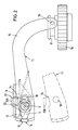
- a gearbox 1 of a transaxel change gear are a variety of transmission shafts in a conventional manner and gear pairs arranged to the different To shift gears, however, are in the present Fig. 1 only those parts of the switching device are shown, which are essential for understanding the invention.
- a vertical shift shaft 3 axially slidably and rotatably arranged to by axial Move a preselection of shift lanes and through Twisting to enable the switching stages to be engaged.
- an upper shift finger 4 and a lower shift finger 5 are arranged on the vertical shift shaft 3 .
- the upper shift finger 4 is in this case known from a per se Link bracket 6 accompanied as a shift lock, the over a pin 7 in a kind of backdrop in a switch housing (only indicated) is fixed against rotation.
- Angle bracket 9 is pivotally mounted about a bolt 10 Reverse gear rocker 11 arranged.
- the angle bracket 9 consists of a vertical angle bracket part 9a, which is attached to the gear housing 1, and from a horizontal angle holder part 9b, which carries the bolt 10.
- the Reverse gear rocker arm 11 has a lever arm 12, the has a groove 13 in the upper end, in which an actuating head 14 engages the lower shift finger 5, and the other Lever arm 15 a bolt 16 is arranged, which is in an actuation ring groove 17 of the reverse gear sliding wheel 18 engages.
- a gate valve 19 is arranged, which consists of a with the Switching shaft 3 rotatably connected via a snap ring 20 Ring part 21 and a cranked locking tongue 22 is made.
- the cranked locking tongue 22 consists of a lower one Part 22a and an upper cranked part 22b, wherein the lower part 22a in a slot 23 in the angle holder 9 axially is guided so that the locking slide against rotation is held with the control shaft 3.
- the bolt 10 for the pivotable mounting of the reverse gear rocker arm 11 can, in order to avoid wobbling, on the Bracket 9 is supported by a lower retaining tab 25 be and receives a wrap leg spring 16, one of which Leg arm 26a is supported on the angle bracket part 9b and whose other arm 26b on the lever arm 15 of the reverse gear rocker arm 11 attacks. In this way the Reverse shift rocker 11 always in its rest position, i.e. held in place with reverse gear disengaged.
Landscapes
- Engineering & Computer Science (AREA)
- General Engineering & Computer Science (AREA)
- Mechanical Engineering (AREA)
- Gear-Shifting Mechanisms (AREA)
Claims (3)
- Dispositif de commande pour une boíte de vitesses à plusieurs rapports avec un moyen de verrouillage de la marche arrière, avec un axe de commande de vitesses (3) placé perpendiculairement dans un carter de boíte de vitesses (1), axe qui est déplaçable axialement pour la présélection de voies de passage de vitesses et est pivotant radialement pour le passage de vitesses, et sur lequel un doigt supérieur et un doigt inférieur (4 et 5) de la fourchette de commande sont prévus pour actionner une multitude de moyens de commande ou de passage de vitesses, un blocage (6 et 19) de passage de vitesses étant attribué à chaque doigt (4 et 5) de la fourchette de commande pour déterminer le moyen de passage de vitesse non sélectionné, caractérisé en ce quele doigt inférieur (5) est prévu pour l'actionnement d'une bielle de commande de marche arrière (11) embrayant dans un pignon de marche arrière (18),le blocage de passage de vitesses attribué au doigt inférieur (5) est formé comme un registre d'arrêt (19) avec une languette de blocage (22) coudée, le registre d'arrêt (19) étant placé de telle sorte qu'il peut être déplacé aussi axialement par l'axe de commande de vitesses (3), mais que la rotation de l'axe de commande de vitesses n'est pas empêché, et en ce qu'il est monté dans une fente (23) d'un support en équerre (9) fixé dans un carter de boíte de vitesses, qui est appliqué dans une fente (23) et est disposé de manière à résister aux torsions, etla bielle de commande de marche arrière (11) est montée de manière pivotante sur le support en équerre (9) à l'aide d'un boulon (10) et présente, sur un bord de côté, une entaille (24) dans laquelle une pièce inférieure (22a) de la languette de blocage (22) a prise en se bloquant lorsque la marche arrière n'est pas sélectionnée.
- Dispositif de changement de vitesses selon la revendication 1, caractérisé en ce que la bielle de marche arrière (11) est munie d'un ressort enrouleur à branches (26) placé autour d'un axe oscillant (10), ressort dont un bras (26a) s'appuie contre la pièce de support en équerre (9a) et dont l'autre bras (26b) a prise sur le bras du levier (15) de la bielle de marche arrière (11) pour maintenir cette dernière en position de repos, c.à.d. lorsque la marche arrière est débrayée.
- Dispositif de changement de vitesses selon les revendications 1 et 2, caractérisé en ce que l'axe pivotant (10) pour le positionnement pivotant de la bielle de commande de marche arrière (11) est soutenu dans le support en équerre (9) à l'aide d'un collier de fixation (25) inférieur supplémentaire pour éviter les nutations.
Applications Claiming Priority (2)
| Application Number | Priority Date | Filing Date | Title |
|---|---|---|---|
| DE19619182 | 1996-05-11 | ||
| DE19619182A DE19619182C2 (de) | 1996-05-11 | 1996-05-11 | Schaltvorrichtung für Wechselgetriebe mit einer Rückwärtsgang-Schaltsperre |
Publications (3)
| Publication Number | Publication Date |
|---|---|
| EP0806593A2 EP0806593A2 (fr) | 1997-11-12 |
| EP0806593A3 EP0806593A3 (fr) | 1999-06-16 |
| EP0806593B1 true EP0806593B1 (fr) | 2001-10-04 |
Family
ID=7794140
Family Applications (1)
| Application Number | Title | Priority Date | Filing Date |
|---|---|---|---|
| EP97107091A Expired - Lifetime EP0806593B1 (fr) | 1996-05-11 | 1997-04-29 | Dispositif de verrouillage de la marche arrière d'une boíte de vitesses à plusieurs rapports |
Country Status (2)
| Country | Link |
|---|---|
| EP (1) | EP0806593B1 (fr) |
| DE (2) | DE19619182C2 (fr) |
Families Citing this family (1)
| Publication number | Priority date | Publication date | Assignee | Title |
|---|---|---|---|---|
| DE102009058377B4 (de) | 2009-12-15 | 2012-12-06 | Getrag Ford Transmissions Gmbh | Verzahnungsanordnung |
Family Cites Families (5)
| Publication number | Priority date | Publication date | Assignee | Title |
|---|---|---|---|---|
| JPS5872222A (ja) * | 1981-10-26 | 1983-04-30 | Nissan Motor Co Ltd | 変速機のシフト装置 |
| AT390038B (de) * | 1983-07-05 | 1990-03-12 | Steyr Daimler Puch Ag | Schaltvorrichtung fuer ein zahnraederwechselgetriebe eines kraftfahrzeuges |
| IT8453633V0 (it) * | 1984-07-11 | 1984-07-11 | Fiat Auto Spa | Dispositivo di comando per un cambio di velocita per autoveicoli |
| IT1190573B (it) * | 1986-05-27 | 1988-02-16 | Fiat Auto Spa | Cambio di velocita a cinque rapporti e retromarcia pe autoveicoli |
| IT1203571B (it) * | 1986-06-10 | 1989-02-15 | Fiat Auto Spa | Dispositivo di innesto della retromarcia per cambi di velocita di autoveicoli |
-
1996
- 1996-05-11 DE DE19619182A patent/DE19619182C2/de not_active Expired - Fee Related
-
1997
- 1997-04-29 EP EP97107091A patent/EP0806593B1/fr not_active Expired - Lifetime
- 1997-04-29 DE DE59704746T patent/DE59704746D1/de not_active Expired - Fee Related
Also Published As
| Publication number | Publication date |
|---|---|
| DE19619182C2 (de) | 1998-07-02 |
| DE59704746D1 (de) | 2001-11-08 |
| DE19619182A1 (de) | 1997-11-13 |
| EP0806593A2 (fr) | 1997-11-12 |
| EP0806593A3 (fr) | 1999-06-16 |
Similar Documents
| Publication | Publication Date | Title |
|---|---|---|
| DE19526059C2 (de) | Schaltvorrichtung für ein automatisches Getriebe eines Kraftfahrzeugs | |
| EP0903518B1 (fr) | Dispostif de changement de vitesses pour transmission véhiculaire | |
| DE3419061C2 (fr) | ||
| EP1224413A1 (fr) | Dispositif de changement de vitesses a une barre destine a des boites de vitesses de vehicules | |
| EP0933563A1 (fr) | Dispositif de changement de vitesses pour transmission de vitesse de véhicule | |
| EP0895007B1 (fr) | Coulisse pour doigt de commande monté sur un arbre de commande changement de vitesses | |
| EP0699853B1 (fr) | Tringlerie de sélection des vitesses pour boîte de vitesse d'un véhicule | |
| DE3927250C2 (fr) | ||
| DE68910890T2 (de) | Mechanismus und dessen arbeitsweise zum positionieren eines gangschalthebels in parkstellung. | |
| EP0999384A1 (fr) | Dispositif de changement de vitesse pour une boíte de vitesse d'un véhicule automobile | |
| DE943742C (de) | Schalteinrichtung fuer Kraftfahrzeuggetriebe | |
| DE4242456C2 (de) | Lagerung eines Handschalthebels einer Schaltvorrichtung eines Zahnräderwechselgetriebes | |
| DE10297643T5 (de) | Getriebeschaltbetätigungsmechanismus | |
| DE19901055A1 (de) | Einwellenschalteinrichtung | |
| EP0790443B1 (fr) | Dispositif de changement de vitesses permettant l'engagement de la marche arrière sans passage au point mort | |
| EP1817513B1 (fr) | Console de changement de vitesses de la boite de vitesses d'un vehicule automobile | |
| WO2006063677A1 (fr) | Dispositif de commutation de boite de vitesses manuelle pour vehicules automobiles | |
| EP0236724A2 (fr) | Dispositif de rappel de l'arbre de commande pour transmission à plusieurs vitesses, en particulier pour véhicules à moteur | |
| DE19619182C2 (de) | Schaltvorrichtung für Wechselgetriebe mit einer Rückwärtsgang-Schaltsperre | |
| DE4121631C2 (fr) | ||
| DE3333423A1 (de) | Mechanische schalteinrichtung | |
| DE19617988C2 (de) | Schaltvorrichtung mit Überschaltsperre | |
| DE2136792A1 (de) | Universalgangschalter fuer elektrische getriebefernsteuerungen | |
| DE2750275A1 (de) | Getriebeschaltung mit schwingen | |
| DE102016213436B4 (de) | Schaltvorrichtung für manuelle Kraftfahrzeuggetriebe mit Schaltgassensperrung |
Legal Events
| Date | Code | Title | Description |
|---|---|---|---|
| PUAI | Public reference made under article 153(3) epc to a published international application that has entered the european phase |
Free format text: ORIGINAL CODE: 0009012 |
|
| AK | Designated contracting states |
Kind code of ref document: A2 Designated state(s): DE FR GB |
|
| RAP1 | Party data changed (applicant data changed or rights of an application transferred) |
Owner name: FORD GLOBAL TECHNOLOGIES, INC. |
|
| PUAL | Search report despatched |
Free format text: ORIGINAL CODE: 0009013 |
|
| AK | Designated contracting states |
Kind code of ref document: A3 Designated state(s): DE FR GB |
|
| RIC1 | Information provided on ipc code assigned before grant |
Free format text: 6F 16H 61/18 A, 6F 16H 63/34 B, 6F 16H 63/30 B |
|
| 17P | Request for examination filed |
Effective date: 19990514 |
|
| GRAG | Despatch of communication of intention to grant |
Free format text: ORIGINAL CODE: EPIDOS AGRA |
|
| 17Q | First examination report despatched |
Effective date: 20010313 |
|
| GRAG | Despatch of communication of intention to grant |
Free format text: ORIGINAL CODE: EPIDOS AGRA |
|
| GRAH | Despatch of communication of intention to grant a patent |
Free format text: ORIGINAL CODE: EPIDOS IGRA |
|
| GRAH | Despatch of communication of intention to grant a patent |
Free format text: ORIGINAL CODE: EPIDOS IGRA |
|
| GRAA | (expected) grant |
Free format text: ORIGINAL CODE: 0009210 |
|
| AK | Designated contracting states |
Kind code of ref document: B1 Designated state(s): DE FR GB |
|
| GBT | Gb: translation of ep patent filed (gb section 77(6)(a)/1977) |
Effective date: 20011004 |
|
| REF | Corresponds to: |
Ref document number: 59704746 Country of ref document: DE Date of ref document: 20011108 |
|
| REG | Reference to a national code |
Ref country code: GB Ref legal event code: IF02 |
|
| ET | Fr: translation filed | ||
| PLBE | No opposition filed within time limit |
Free format text: ORIGINAL CODE: 0009261 |
|
| STAA | Information on the status of an ep patent application or granted ep patent |
Free format text: STATUS: NO OPPOSITION FILED WITHIN TIME LIMIT |
|
| 26N | No opposition filed | ||
| REG | Reference to a national code |
Ref country code: GB Ref legal event code: 732E |
|
| PGFP | Annual fee paid to national office [announced via postgrant information from national office to epo] |
Ref country code: GB Payment date: 20050314 Year of fee payment: 9 |
|
| PGFP | Annual fee paid to national office [announced via postgrant information from national office to epo] |
Ref country code: FR Payment date: 20050401 Year of fee payment: 9 |
|
| REG | Reference to a national code |
Ref country code: FR Ref legal event code: TP |
|
| PGFP | Annual fee paid to national office [announced via postgrant information from national office to epo] |
Ref country code: DE Payment date: 20050429 Year of fee payment: 9 |
|
| PG25 | Lapsed in a contracting state [announced via postgrant information from national office to epo] |
Ref country code: GB Free format text: LAPSE BECAUSE OF NON-PAYMENT OF DUE FEES Effective date: 20060429 |
|
| PG25 | Lapsed in a contracting state [announced via postgrant information from national office to epo] |
Ref country code: DE Free format text: LAPSE BECAUSE OF NON-PAYMENT OF DUE FEES Effective date: 20061101 |
|
| GBPC | Gb: european patent ceased through non-payment of renewal fee |
Effective date: 20060429 |
|
| REG | Reference to a national code |
Ref country code: FR Ref legal event code: ST Effective date: 20061230 |
|
| PG25 | Lapsed in a contracting state [announced via postgrant information from national office to epo] |
Ref country code: FR Free format text: LAPSE BECAUSE OF NON-PAYMENT OF DUE FEES Effective date: 20060502 |