EP0806603B1 - Verfahren und Einrichtung zum automatischen Zuführen von Schmiermittel unter Benutzung eines Mikrokomputers - Google Patents
Verfahren und Einrichtung zum automatischen Zuführen von Schmiermittel unter Benutzung eines Mikrokomputers Download PDFInfo
- Publication number
- EP0806603B1 EP0806603B1 EP97300189A EP97300189A EP0806603B1 EP 0806603 B1 EP0806603 B1 EP 0806603B1 EP 97300189 A EP97300189 A EP 97300189A EP 97300189 A EP97300189 A EP 97300189A EP 0806603 B1 EP0806603 B1 EP 0806603B1
- Authority
- EP
- European Patent Office
- Prior art keywords
- lubricating oil
- discharge
- mode
- microcomputer
- electrochemical reactor
- Prior art date
- Legal status (The legal status is an assumption and is not a legal conclusion. Google has not performed a legal analysis and makes no representation as to the accuracy of the status listed.)
- Expired - Lifetime
Links
- 239000010687 lubricating oil Substances 0.000 title claims description 49
- 238000000034 method Methods 0.000 title claims description 12
- 239000004973 liquid crystal related substance Substances 0.000 claims description 6
- 238000010926 purge Methods 0.000 claims description 6
- 230000035484 reaction time Effects 0.000 description 6
- 238000010586 diagram Methods 0.000 description 5
- 238000003487 electrochemical reaction Methods 0.000 description 2
- 238000007599 discharging Methods 0.000 description 1
- 230000007613 environmental effect Effects 0.000 description 1
- 238000012840 feeding operation Methods 0.000 description 1
- 239000004519 grease Substances 0.000 description 1
- 239000003921 oil Substances 0.000 description 1
Images


Classifications
-
- F—MECHANICAL ENGINEERING; LIGHTING; HEATING; WEAPONS; BLASTING
- F16—ENGINEERING ELEMENTS AND UNITS; GENERAL MEASURES FOR PRODUCING AND MAINTAINING EFFECTIVE FUNCTIONING OF MACHINES OR INSTALLATIONS; THERMAL INSULATION IN GENERAL
- F16N—LUBRICATING
- F16N7/00—Arrangements for supplying oil or unspecified lubricant from a stationary reservoir or the equivalent in or on the machine or member to be lubricated
-
- F—MECHANICAL ENGINEERING; LIGHTING; HEATING; WEAPONS; BLASTING
- F16—ENGINEERING ELEMENTS AND UNITS; GENERAL MEASURES FOR PRODUCING AND MAINTAINING EFFECTIVE FUNCTIONING OF MACHINES OR INSTALLATIONS; THERMAL INSULATION IN GENERAL
- F16N—LUBRICATING
- F16N11/00—Arrangements for supplying grease from a stationary reservoir or the equivalent in or on the machine or member to be lubricated; Grease cups
- F16N11/10—Arrangements for supplying grease from a stationary reservoir or the equivalent in or on the machine or member to be lubricated; Grease cups by pressure of another fluid
-
- F—MECHANICAL ENGINEERING; LIGHTING; HEATING; WEAPONS; BLASTING
- F16—ENGINEERING ELEMENTS AND UNITS; GENERAL MEASURES FOR PRODUCING AND MAINTAINING EFFECTIVE FUNCTIONING OF MACHINES OR INSTALLATIONS; THERMAL INSULATION IN GENERAL
- F16N—LUBRICATING
- F16N2230/00—Signal processing
- F16N2230/02—Microprocessor; Microcomputer
-
- F—MECHANICAL ENGINEERING; LIGHTING; HEATING; WEAPONS; BLASTING
- F16—ENGINEERING ELEMENTS AND UNITS; GENERAL MEASURES FOR PRODUCING AND MAINTAINING EFFECTIVE FUNCTIONING OF MACHINES OR INSTALLATIONS; THERMAL INSULATION IN GENERAL
- F16N—LUBRICATING
- F16N2230/00—Signal processing
- F16N2230/10—Timing network
-
- F—MECHANICAL ENGINEERING; LIGHTING; HEATING; WEAPONS; BLASTING
- F16—ENGINEERING ELEMENTS AND UNITS; GENERAL MEASURES FOR PRODUCING AND MAINTAINING EFFECTIVE FUNCTIONING OF MACHINES OR INSTALLATIONS; THERMAL INSULATION IN GENERAL
- F16N—LUBRICATING
- F16N2260/00—Fail safe
- F16N2260/02—Indicating
- F16N2260/12—Indicating using warning lamps
-
- F—MECHANICAL ENGINEERING; LIGHTING; HEATING; WEAPONS; BLASTING
- F16—ENGINEERING ELEMENTS AND UNITS; GENERAL MEASURES FOR PRODUCING AND MAINTAINING EFFECTIVE FUNCTIONING OF MACHINES OR INSTALLATIONS; THERMAL INSULATION IN GENERAL
- F16N—LUBRICATING
- F16N2270/00—Controlling
- F16N2270/20—Amount of lubricant
- F16N2270/30—Amount of lubricant intermittent
Definitions
- the present invention relates to a method and apparatus for automatically feeding lubricating oil to bearing portions of various machine parts (US 5 381 874).
- the present invention relates to a method and apparatus for automatically feeding lubricating oil using a microcomputer whereby when a predetermined time for discharging lubricating oil terminates, a discharge mode for a minimum time, for example, for one month, is set to completely discharge the remaining lubricating oil, and the predetermined discharge time is displayed by a display device.
- Such an automatic lubricating oil feeding apparatus has advantages in that it can continuously feed lubricating oil to places which need the lubricating oil such as bearings without the necessity of a manual feeding operation.
- the lubricating oil is automatically discharged by a piston which moves downward by a diaphragm.
- This diaphragm is extended to move the piston by gas pressure provided by an electrochemical reactor.
- the gas reaction time and the gas pressure of the electrochemical reactor are adjusted by a control circuit, and thus the discharge of lubricating oil can be automatically performed extending from several months to several tens of months.
- FIG. 1 is a schematic circuit diagram of a conventional lubricating oil feeding apparatus.
- a plurality of resistors R1 to R5 and a plurality of switches S1 to S5 are connected in series to adjust the current flowing to the electrochemical reactor 20.
- a display section for visually indicating the operation of the electrochemical reactor 20 is composed of a light-emitting diode LED, driving transistors Q1 to Q3, and resistors.
- the amount of current applied to the electrochemical reactor 20 is varied in accordance with a specific resistance determined by the on/off state of the switches S1 to S5 to adjust the reaction time of the electrochemical reactor (e.g., gas chamber) 20.
- the reaction time corresponds to the lubricating oil discharge time, and is extended from one month to several months.
- the light-emitting diode is turned on to display the operating state of the electrochemical reactor.
- the electrochemical reaction time is adjusted by controlling the current consumption of the electrochemical reactor and the current consumption is controlled according to the resistance selected by the switches S1 to S5.
- the conventional apparatus has drawbacks in that the environmental conditions such as the condition inside the bearing portion, the temperature change, etc., cannot be reflected in controlling the lubricating oil discharge time. Further, as time goes by, the internal resistance of the electrochemical reactor (e.g., gas chamber) may vary, causing the current consumption of the reactor also to vary. This causes the proper and accurate discharge of lubricating oil in time and in amount not to be achieved.
- the electrochemical reactor e.g., gas chamber
- the predetermined discharge time can be recognized only by checking the on/off state of the switches to cause inconvenience in use. Further, in the event that a portion of the lubricating oil still remains due to the external or internal factors when the predetermined discharge time elapses, a user cannot identify whether or not the amount of the remaining lubricating oil is sufficient for setting of the discharge time again, and thus he can but discard the remaining oil.
- an automatic lubricating oil feeding apparatus using an electrochemical reactor comprising:
- a method of automatically feeding lubricating oil using an electrochemical reactor comprising the steps of:
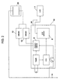
- the automatic lubricating oil feeding apparatus includes a microcomputer 10 capable of storing and computing input data and performing an input/output control, a mode switch MS for determining and inputting discharge time data of lubricating oil to the microcomputer 10, a liquid crystal display (LCD) 11 which is driven by an LCD driver 8 provided in the microcomputer 10, a purge driver 12 which is driven by the maximum output of a power driver 6 provided in the microcomputer 10, a driver 13 which is driven by an output of the power driver 6 corresponding to a selected mode, and an electrochemical reactor 20 receiving its operating power supply B + through the purge driver 12 and the driver 13.
- a microcomputer 10 capable of storing and computing input data and performing an input/output control
- a mode switch MS for determining and inputting discharge time data of lubricating oil to the microcomputer 10
- LCD liquid crystal display
- purge driver 12 which is driven by the maximum output of a power driver 6 provided in the microcomputer
- a driver 13 which is driven by an output of the power driver 6 corresponding to a
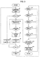
- the lubricating oil feeding apparatus is properly installed in a required machine parts. If a user manipulates the mode switch MS to select a discharge mode, the microcomputer 10 performs an operating month input mode (step S1 in FIG. 3), for example, for selecting one of 1, 2, 3, 6, and 12-month modes. If it is determined that the selected mode is a purge mode (step S2 in FIG, 3), the microcomputer 10 turns on its output port (step S3 in FIG. 3) to operate the electrochemical reactor 20 with its maximum electrochemical reaction level.
- the term "on-state of the output port" means a 'LOW' logic level.
- the output of the power driver 6 is applied to the purge driver 12, and the power supply B + flows to the driver 12 through the electrochemical reactor 20, causing the lubricating oil to be discharged.
- the microcomputer 10 performs its control operation in accordance with the corresponding input mode.
- the term "off-state of the output port" means a 'HIGH' logic level.
- the reaction time of the electrochemical reactor 20 is controlled in such a manner that, in order to control the discharge amount of the lubricating oil, the operating time for each selected mode, i.e., the K time, is determined by the amount of the current consumption of the electrochemical reactor 20, which is obtained by computing an expression I ⁇ TM ⁇ TC, where I is the amount of current, TC is a unit time, and TM is the output time according to the selected mode.
- the K time for each mode is calculated by multiplying Xt by the efficiency of the gas chamber which is converted from the specific resistance value of the gas chamber in accordance with the passed time.
- step S15 in FIG. 3 the set discharge mode is cleared, and the discharge mode for the minimum time, i.e., for one month, is set under the control of the microcomputer 10 (step.S16 in FIG. 3), so that the remaining lubricating oil is completely discharged during the minimum time.
- the power driver 6 and the driver 13 operate for the one-month mode until the power supply B + being supplied thereto is expired.
- the set mode is displayed on the LCD as the number of discharge months, and thus a user can easily recognize the discharge months of the present mode.
Landscapes
- Engineering & Computer Science (AREA)
- General Engineering & Computer Science (AREA)
- Mechanical Engineering (AREA)
- Control Of Positive-Displacement Pumps (AREA)
- Charge And Discharge Circuits For Batteries Or The Like (AREA)
- General Details Of Gearings (AREA)
- Management, Administration, Business Operations System, And Electronic Commerce (AREA)
Claims (3)
- Automatisches Schmieröl-Zuführungsverfahren, das einen elektrochemischen Reaktor verwendet, wobei das Verfahren die folgenden Schritte umfasst:Bestimmen einer Abgabezeit von Schmieröl für jeden Abgabemodus, der eingestellt werden soll;Steuern des Betriebs des elektrochemischen Reaktors in Übereinstimmung mit der bestimmten Abgabezeit;Erfassen eines Abschlusses des eingestellten Abgabemodus;Einstellen eines Abgabemodus für eine minimale Abgabezeit, wenn der eingestellte Abgabemodus abgeschlossen ist, um das verbleibende Schmieröl schnell abzugeben.
- Automatische Schmieröl-Zuführungsvorrichtung, wobei die Vorrichtung umfasst:dadurch gekennzeichnet, dass die Anzeige eine Flüssigkristallanzeige ist und dass die Vorrichtung einen elektrochemischen Reaktor verwendet.einen Modus-Wählschalter zum Wählen eines Abgabemodus von Schmieröl;einen Mikrocomputer zum Berechnen einer Abgabezeit gemäß dem gewählten Modus und Bereitstellen eines Steuersignals, dass der berechneten Abgabezeit entspricht, an dem elektrochemischen Reaktor;eine Anzeige zum Anzeigen des gewählten Modus und/oder der berechneten Abgabezeit unter Steuerung des Mikrocomputers,
- Automatische Schmieröl-Zuführungsvorrichtung nach Anspruch 2, ferner umfassend:einen Flüssigkristallanzeige-Ansteuerer zum Ansteuern der Flüssigkristallanzeige unter der Steuerung des Mikrocomputers;einen Ausräumungs-Ansteuerer zum Ansteuern des elektrochemischen Reaktors mit einem maximalen Ausgang unter der Steuerung des Mikrocomputers; undeinen Ansteuerer zum Ansteuern des elektrochemischen Reaktors in Übereinstimmung mit dem gewählten Modus unter der Steuerung des Mikrocomputers.
Applications Claiming Priority (2)
| Application Number | Priority Date | Filing Date | Title |
|---|---|---|---|
| KR1019960014738A KR100189152B1 (ko) | 1996-05-06 | 1996-05-06 | 마이컴을 이용한 윤활유 자동공급방법 및 장치 |
| KR9614738 | 1996-05-06 |
Publications (2)
| Publication Number | Publication Date |
|---|---|
| EP0806603A1 EP0806603A1 (de) | 1997-11-12 |
| EP0806603B1 true EP0806603B1 (de) | 2003-07-09 |
Family
ID=19457856
Family Applications (1)
| Application Number | Title | Priority Date | Filing Date |
|---|---|---|---|
| EP97300189A Expired - Lifetime EP0806603B1 (de) | 1996-05-06 | 1997-01-14 | Verfahren und Einrichtung zum automatischen Zuführen von Schmiermittel unter Benutzung eines Mikrokomputers |
Country Status (4)
| Country | Link |
|---|---|
| US (1) | US5788012A (de) |
| EP (1) | EP0806603B1 (de) |
| KR (1) | KR100189152B1 (de) |
| DE (1) | DE69723355T2 (de) |
Cited By (2)
| Publication number | Priority date | Publication date | Assignee | Title |
|---|---|---|---|---|
| WO2010099813A1 (de) | 2009-03-05 | 2010-09-10 | Perma-Tec Gmbh & Co. Kg | Verfahren zur dosierten abgabe von schmierstoff |
| WO2010099812A1 (de) | 2009-03-05 | 2010-09-10 | Perma-Tec Gmbh & Co.Kg | Schmierstoffspender |
Families Citing this family (14)
| Publication number | Priority date | Publication date | Assignee | Title |
|---|---|---|---|---|
| US6012551A (en) * | 1995-04-15 | 2000-01-11 | Gerhard Dohring | Apparatus for automatic lubricant delivery |
| KR100272677B1 (ko) * | 1998-02-02 | 2001-04-02 | 양 윤 종 | 중앙집중 관리가 가능한 윤활유 자동 공급 시스템 |
| DE19857289C1 (de) * | 1998-12-13 | 2000-05-04 | Brueckner Maschbau | Verfahren zur Schmierung von Transportsystemen oder Teilen davon sowie Verwendung einer Schmiermittelvorrichtung zur Durchführung des Verfahrens und ein zugehöriges Transportsystem mit entsprechender Schmiermitteleinrichtung |
| KR100282129B1 (ko) * | 1999-12-02 | 2001-02-15 | 양윤종 | 마이컴을 이용한 윤활유 자동공급방법 |
| DE10054712C2 (de) * | 2000-11-04 | 2002-10-24 | Walterscheid Gmbh Gkn | Schaltungsanordnung zur Betätigung eines Schmiermittelspenders und Verfahren hierfür |
| DE102007021376B4 (de) | 2007-05-04 | 2009-10-01 | Perma-Tec Gmbh & Co. Kg | Verfahren zum Betrieb eines Schmierstoffspenders |
| US8695763B2 (en) * | 2008-03-26 | 2014-04-15 | Haas Automation, Inc. | Smart machine tool lubrication system |
| KR101284597B1 (ko) | 2012-05-08 | 2013-07-10 | 주식회사 루브캡이엔에스 | 기계설비의 윤활유 자동 공급 제어용 컨트롤러 |
| DE102012111239B4 (de) * | 2012-11-21 | 2016-08-25 | Perma-Tec Gmbh & Co. Kg | Verfahren zur dosierten Abgabe eines Schmierstoffes |
| DE102012111376A1 (de) * | 2012-11-23 | 2014-05-28 | Perma-Tec Gmbh & Co. Kg | Verfahren zur dosierten Abgabe von Schmierfett mittels eines Schmierstoffspenders |
| CN105508859A (zh) * | 2015-12-29 | 2016-04-20 | 中国神华能源股份有限公司 | 一种控制林肯泵的系统 |
| CN107544345B (zh) * | 2017-09-28 | 2019-08-02 | 中原工学院 | 一种火车轮轨曲线运动智能润滑控制系统 |
| CN107937979A (zh) * | 2017-12-11 | 2018-04-20 | 中国电子科技集团公司第四十六研究所 | 气相法晶体生长压力系统的模糊自适应控制方法 |
| CN112210825A (zh) * | 2020-09-15 | 2021-01-12 | 中国电子科技集团公司第四十六研究所 | 大流量气相法晶体生长的压力自适应模糊控制方法 |
Family Cites Families (20)
| Publication number | Priority date | Publication date | Assignee | Title |
|---|---|---|---|---|
| US2852098A (en) * | 1955-11-02 | 1958-09-16 | Albin N Benson | Continual pressure grease cup |
| US3367545A (en) * | 1965-09-15 | 1968-02-06 | Products Res & Chemical Corp | Gas-generating dispenser for viscous materials |
| DE2139771C3 (de) * | 1971-08-09 | 1979-04-26 | Roland 8731 Euerdorf Satzinger | Selbsttätig Schmierstoff abgebende Schmierbüchse |
| US4023469A (en) * | 1972-08-09 | 1977-05-17 | United States Steel Corporation | Piston and piston rod construction for pumps and method of flushing piston-type pumps |
| US4023648A (en) * | 1974-05-09 | 1977-05-17 | Anton Orlitzky | Lubricant applicators |
| US4023468A (en) * | 1976-01-09 | 1977-05-17 | Thermo Electron Corporation | Blood pump stroke volume limiter |
| US4445168A (en) * | 1981-06-24 | 1984-04-24 | Houdaille Industries, Inc. | Apparatus and method for micro-computer control of lubrication system |
| NL8501839A (nl) * | 1985-06-26 | 1987-01-16 | Skf Ind Trading & Dev | Inrichting voor het toedienen van een smeermiddel. |
| EP0278138B1 (de) * | 1987-02-11 | 1991-07-17 | ORLITZKY, Anton | Schmiereinrichtung |
| US4671386A (en) * | 1985-10-01 | 1987-06-09 | Anton Orlitzky | Lubricating apparatus |
| DE3644207A1 (de) * | 1986-12-23 | 1988-07-07 | Satzinger Gebhard Gmbh Co | Vorrichtung zum kontinuierlichen zufuehren von fluessigen oder viskosen medien, insbesondere von schmierstoffen |
| EP0362328B1 (de) * | 1988-03-16 | 1995-08-09 | WYSSMANN, Max | Schmierstoffgeber |
| US5425706A (en) * | 1989-02-24 | 1995-06-20 | S. I. Scientific Innovations Ltd. | Dispensing device particularly useful for dispensing nutritional liquids |
| FR2649617A1 (fr) * | 1989-07-12 | 1991-01-18 | Veprol | Dispositif de delivrance d'un principe actif pharmacologique par pompage electrolytique |
| US5038893A (en) * | 1989-09-25 | 1991-08-13 | Orsco, Inc. | Lubrication monitoring system |
| AU659248B2 (en) * | 1991-11-22 | 1995-05-11 | Denis Arthur John Patterson | A dispensing device |
| KR0110998Y1 (en) * | 1992-12-01 | 1997-12-22 | Hankuk Lubrication Technology | Device for supplying lubrication oil |
| DE4241073C1 (de) * | 1992-12-05 | 1994-06-01 | Satzinger Gmbh & Co | Apparat für die dosierte Abgabe von einem Fluid, insbesondere von einem Schmiermittelfluid |
| US5381874A (en) * | 1993-10-15 | 1995-01-17 | Caterpillar Inc. | Automatic lubrication control |
| US5622239A (en) * | 1995-07-14 | 1997-04-22 | A.T.S. Electro-Lube Holdings Ltd. | Gear wheel lubricator |
-
1996
- 1996-05-06 KR KR1019960014738A patent/KR100189152B1/ko not_active Expired - Lifetime
-
1997
- 1997-01-14 DE DE69723355T patent/DE69723355T2/de not_active Expired - Fee Related
- 1997-01-14 EP EP97300189A patent/EP0806603B1/de not_active Expired - Lifetime
- 1997-02-05 US US08/794,897 patent/US5788012A/en not_active Expired - Lifetime
Cited By (8)
| Publication number | Priority date | Publication date | Assignee | Title |
|---|---|---|---|---|
| WO2010099813A1 (de) | 2009-03-05 | 2010-09-10 | Perma-Tec Gmbh & Co. Kg | Verfahren zur dosierten abgabe von schmierstoff |
| WO2010099812A1 (de) | 2009-03-05 | 2010-09-10 | Perma-Tec Gmbh & Co.Kg | Schmierstoffspender |
| DE102009022707A1 (de) | 2009-03-05 | 2010-09-16 | Perma-Tec Gmbh & Co. Kg | Schmierstoffspender |
| DE102009021628A1 (de) | 2009-03-05 | 2010-09-16 | Perma-Tec Gmbh & Co. Kg | Verfahren zur dosierten Abgabe von Schmierstoff |
| DE102009021628B4 (de) * | 2009-03-05 | 2011-06-01 | Perma-Tec Gmbh & Co. Kg | Verfahren zur dosierten Abgabe von Schmierstoffen |
| CN102341635A (zh) * | 2009-03-05 | 2012-02-01 | 佩玛技术两合有限公司 | 用于定量输出润滑剂的方法 |
| DE102009022707B4 (de) * | 2009-03-05 | 2014-03-27 | Perma-Tec Gmbh & Co. Kg | Schmierstoffspender |
| CN102341635B (zh) * | 2009-03-05 | 2015-09-09 | 佩玛技术两合有限公司 | 用于定量输出润滑剂的方法 |
Also Published As
| Publication number | Publication date |
|---|---|
| EP0806603A1 (de) | 1997-11-12 |
| US5788012A (en) | 1998-08-04 |
| DE69723355D1 (de) | 2003-08-14 |
| DE69723355T2 (de) | 2004-05-27 |
| KR970075632A (ko) | 1997-12-10 |
| KR100189152B1 (ko) | 1999-06-01 |
Similar Documents
| Publication | Publication Date | Title |
|---|---|---|
| EP0806603B1 (de) | Verfahren und Einrichtung zum automatischen Zuführen von Schmiermittel unter Benutzung eines Mikrokomputers | |
| US4984185A (en) | Portable computer having a battery voltage detecting circuit | |
| EP0245113A2 (de) | Luftzustands-Überwachungseinheit | |
| SE449708B (sv) | Sett och anordning for adaptiv styrning av en verktygsmaskin | |
| US7110896B2 (en) | System and method for displaying battery status and other parameters of a portable electronic device in a power-off state | |
| EP0594006B1 (de) | Batteriebetriebener Datenprozessor | |
| JP2007199075A (ja) | 電池種別識別装置およびカメラ | |
| KR20040106362A (ko) | 저 전압 표시기가 있는 원격제어장치 | |
| US5784295A (en) | Method and apparatus for determining residual battery voltage | |
| KR100282129B1 (ko) | 마이컴을 이용한 윤활유 자동공급방법 | |
| US4365289A (en) | Method and control system for controlling apparatus | |
| US4010456A (en) | Low battery voltage indicator for a portable digital electronic instrument | |
| US11874205B2 (en) | Gas chromatograph | |
| US4932244A (en) | Display device for an engine-equipped machine | |
| KR100356700B1 (ko) | 휴대용 컴퓨터의 리튬이온 배터리팩을 검사하는 장치 | |
| JP2005195352A (ja) | 電池残量表示方法 | |
| EP0102373B1 (de) | GERäT ZUR SCHRITT SEQUENTIELLEN STEUERUNG | |
| KR100368941B1 (ko) | 냉장고 및 그 제어방법 | |
| KR0137858B1 (ko) | 원키 리모콘의 세트 조작 방법 | |
| JPH04274777A (ja) | Ni−Cd電池の残量検出回路 | |
| KR0135830B1 (ko) | 디스플레이 가능한 리모콘장치 및 구동방법 | |
| KR100423480B1 (ko) | 복수의 토너농도센서를 가지는 프린터 및 그의토너공급제어방법 | |
| JPH0655133U (ja) | 液晶表示器の駆動制御装置 | |
| KR200284773Y1 (ko) | 7세그먼트를 이용하여 수신체크가 가능한 프론트 판넬을갖는 전자제품 | |
| KR940009067B1 (ko) | 유량검지식 급수장치 |
Legal Events
| Date | Code | Title | Description |
|---|---|---|---|
| PUAI | Public reference made under article 153(3) epc to a published international application that has entered the european phase |
Free format text: ORIGINAL CODE: 0009012 |
|
| AK | Designated contracting states |
Kind code of ref document: A1 Designated state(s): DE FR GB |
|
| 17P | Request for examination filed |
Effective date: 19980313 |
|
| 17Q | First examination report despatched |
Effective date: 20020222 |
|
| GRAH | Despatch of communication of intention to grant a patent |
Free format text: ORIGINAL CODE: EPIDOS IGRA |
|
| GRAH | Despatch of communication of intention to grant a patent |
Free format text: ORIGINAL CODE: EPIDOS IGRA |
|
| GRAA | (expected) grant |
Free format text: ORIGINAL CODE: 0009210 |
|
| AK | Designated contracting states |
Designated state(s): DE FR GB |
|
| REG | Reference to a national code |
Ref country code: GB Ref legal event code: FG4D |
|
| REF | Corresponds to: |
Ref document number: 69723355 Country of ref document: DE Date of ref document: 20030814 Kind code of ref document: P |
|
| PG25 | Lapsed in a contracting state [announced via postgrant information from national office to epo] |
Ref country code: GB Free format text: LAPSE BECAUSE OF NON-PAYMENT OF DUE FEES Effective date: 20040114 |
|
| PLBE | No opposition filed within time limit |
Free format text: ORIGINAL CODE: 0009261 |
|
| STAA | Information on the status of an ep patent application or granted ep patent |
Free format text: STATUS: NO OPPOSITION FILED WITHIN TIME LIMIT |
|
| ET | Fr: translation filed | ||
| 26N | No opposition filed |
Effective date: 20040414 |
|
| PG25 | Lapsed in a contracting state [announced via postgrant information from national office to epo] |
Ref country code: DE Free format text: LAPSE BECAUSE OF NON-PAYMENT OF DUE FEES Effective date: 20040803 |
|
| GBPC | Gb: european patent ceased through non-payment of renewal fee |
Effective date: 20040114 |
|
| REG | Reference to a national code |
Ref country code: FR Ref legal event code: ST Effective date: 20080229 |
|
| PG25 | Lapsed in a contracting state [announced via postgrant information from national office to epo] |
Ref country code: FR Free format text: LAPSE BECAUSE OF NON-PAYMENT OF DUE FEES Effective date: 20040131 |