EP0806611A1 - Injektionssystem mit variabler Geometrie durch Änderung des Luftdurchsatzes in Hinsicht auf Motorbelastung - Google Patents
Injektionssystem mit variabler Geometrie durch Änderung des Luftdurchsatzes in Hinsicht auf Motorbelastung Download PDFInfo
- Publication number
- EP0806611A1 EP0806611A1 EP97401023A EP97401023A EP0806611A1 EP 0806611 A1 EP0806611 A1 EP 0806611A1 EP 97401023 A EP97401023 A EP 97401023A EP 97401023 A EP97401023 A EP 97401023A EP 0806611 A1 EP0806611 A1 EP 0806611A1
- Authority
- EP
- European Patent Office
- Prior art keywords
- fuel
- shutter
- bellows
- inlet tube
- coaxial
- Prior art date
- Legal status (The legal status is an assumption and is not a legal conclusion. Google has not performed a legal analysis and makes no representation as to the accuracy of the status listed.)
- Withdrawn
Links
- 238000002347 injection Methods 0.000 title claims description 17
- 239000007924 injection Substances 0.000 title claims description 17
- 239000000446 fuel Substances 0.000 claims abstract description 77
- 238000002485 combustion reaction Methods 0.000 claims abstract description 26
- 230000005489 elastic deformation Effects 0.000 claims abstract description 3
- 239000002184 metal Substances 0.000 abstract 1
- MWUXSHHQAYIFBG-UHFFFAOYSA-N nitrogen oxide Inorganic materials O=[N] MWUXSHHQAYIFBG-UHFFFAOYSA-N 0.000 description 9
- 239000007789 gas Substances 0.000 description 6
- 239000000203 mixture Substances 0.000 description 5
- CURLTUGMZLYLDI-UHFFFAOYSA-N Carbon dioxide Chemical compound O=C=O CURLTUGMZLYLDI-UHFFFAOYSA-N 0.000 description 4
- 238000011144 upstream manufacturing Methods 0.000 description 4
- 229910002092 carbon dioxide Inorganic materials 0.000 description 2
- 239000001569 carbon dioxide Substances 0.000 description 2
- 239000000567 combustion gas Substances 0.000 description 2
- 238000006073 displacement reaction Methods 0.000 description 2
- 239000012528 membrane Substances 0.000 description 2
- 239000000779 smoke Substances 0.000 description 2
- 230000000694 effects Effects 0.000 description 1
- 239000012530 fluid Substances 0.000 description 1
- 239000007800 oxidant agent Substances 0.000 description 1
- 230000036632 reaction speed Effects 0.000 description 1
- 238000005096 rolling process Methods 0.000 description 1
- 238000010008 shearing Methods 0.000 description 1
- 238000005507 spraying Methods 0.000 description 1
- 238000010200 validation analysis Methods 0.000 description 1
Images


Classifications
-
- F—MECHANICAL ENGINEERING; LIGHTING; HEATING; WEAPONS; BLASTING
- F23—COMBUSTION APPARATUS; COMBUSTION PROCESSES
- F23R—GENERATING COMBUSTION PRODUCTS OF HIGH PRESSURE OR HIGH VELOCITY, e.g. GAS-TURBINE COMBUSTION CHAMBERS
- F23R3/00—Continuous combustion chambers using liquid or gaseous fuel
- F23R3/02—Continuous combustion chambers using liquid or gaseous fuel characterised by the air-flow or gas-flow configuration
- F23R3/26—Controlling the air flow
-
- F—MECHANICAL ENGINEERING; LIGHTING; HEATING; WEAPONS; BLASTING
- F23—COMBUSTION APPARATUS; COMBUSTION PROCESSES
- F23R—GENERATING COMBUSTION PRODUCTS OF HIGH PRESSURE OR HIGH VELOCITY, e.g. GAS-TURBINE COMBUSTION CHAMBERS
- F23R2900/00—Special features of, or arrangements for continuous combustion chambers; Combustion processes therefor
- F23R2900/00001—Arrangements using bellows, e.g. to adjust volumes or reduce thermal stresses
-
- Y—GENERAL TAGGING OF NEW TECHNOLOGICAL DEVELOPMENTS; GENERAL TAGGING OF CROSS-SECTIONAL TECHNOLOGIES SPANNING OVER SEVERAL SECTIONS OF THE IPC; TECHNICAL SUBJECTS COVERED BY FORMER USPC CROSS-REFERENCE ART COLLECTIONS [XRACs] AND DIGESTS
- Y02—TECHNOLOGIES OR APPLICATIONS FOR MITIGATION OR ADAPTATION AGAINST CLIMATE CHANGE
- Y02E—REDUCTION OF GREENHOUSE GAS [GHG] EMISSIONS, RELATED TO ENERGY GENERATION, TRANSMISSION OR DISTRIBUTION
- Y02E20/00—Combustion technologies with mitigation potential
- Y02E20/34—Indirect CO2mitigation, i.e. by acting on non CO2directly related matters of the process, e.g. pre-heating or heat recovery
Definitions
- the present invention relates to a burner for the combustion chamber of a gas turbine engine comprising a fuel injection device fixed in the bottom of the chamber, and supplied with fuel by at least one fuel inlet tube. , an inner spin associated with said fuel injection device and intended to supply primary air participating in the combustion of the injected fuel, means for adjusting the air flow rate supplied by the inner spin and means for controlling the means adjustment acting according to the engine speed.
- turbomachinery which will equip civil and military aircraft must be as least polluting as possible. They will have to emit a minimum of carbon dioxide and nitrogen oxides, both during takeoff and climb in altitude and during the cruise period. This is how the fuel injection and oxidizer devices and the combustion chamber must be optimized. In addition, in the case of aircraft for military use, smoke emissions must be extremely reduced and if possible non-existent, since discretion is a very important parameter.
- the air and fuel flow rates change strongly as a function of the rotation speeds and the supply conditions; and the air / fuel richness differences are significant between the idle and full throttle speeds.
- the air / fuel mixture is lean, which is harmful in terms of pollution, especially carbon dioxide.
- the values of air flow, pressure, temperature and air / fuel richness are relatively low, which results in slow reaction speeds. This is why at low speeds it is necessary to limit the air flow to enrich the primary zone of the combustion chamber. It is also necessary to obtain a very large fuel sheet in order to increase the residence time of the combustion gases in the chamber.
- FR-A-2 270 448 describes a combustion chamber, in which a membrane carried by bellows hermetically closes the air intake at the entry of the blade vane crown. The more the engine speed increases, the more the inlet air pressure increases. This has the effect of rolling back the membrane so as to open the air intakes. It should be noted that in the chamber described in this document, the fresh air coming from the compressor is supplied against the flow of the combustion gases.
- the means for adjusting the tendrils comprise pivoting rings controlled together either mechanically by cams or by the pressure of the fluid in the combustion chamber.
- the object of the present invention is to provide a burner of the type mentioned above, the adjustment means of which are stable at low speeds and at high speeds and the control means of which act as a function of the fuel supply pressure of said burner. independently of the other burners that can equip the combustion chamber.
- the burner according to the present invention is characterized in that the means for adjusting the air flow rate comprise a shutter movable axially between a position for closing the inner spin at low speed and a maximum opening position at high speed, said shutter being carried by elastic bellows which connect it to the fuel inlet tube, on the one hand, and to the fuel injection device, on the other hand, and which ensure the continuity of the fuel circuit between the tube inlet and the injection device, and by the fact that the control means of the adjustment means are constituted by the elastic deformations of said bellows under the action of the pressure of the fuel supplied by the inlet tube.
- Each shutter is thus stable, both for very low speeds and for very high speeds.
- Each injection system or burner is a module in its own right, independent of the other modules of the combustion chamber, and can be adjusted in its operating range independently. The adjustment of each module can be carried out outside the combustion chamber or outside the engine, thus offering the possibility of replacement on the engine without affecting the other combustion chamber injection systems.
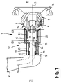
- FIG. 1 there is shown by reference 1 a burner fitted to a combustion chamber of a gas turbine engine.
- This burner 1 comprises a body 2 fixed to the engine casing, not shown in the drawing, and in which is arranged a fuel inlet tube 3, a fuel injection device 4 or nozzle centered in a pot 5 fixed in the bottom 6 of the combustion chamber, an inner spin 7 associated with the nozzle 4 and intended to provide a swirling primary air flow which participates in the shearing and spraying of the fuel sheet delivered by the nozzle 4, and the combustion of this fuel, in the combustion zone 8 of the combustion chamber.
- the end piece 4 is arranged at a distance from the body 2. As can be seen in FIG. 1, between the downstream face 10 of the body 2, perpendicular to the axis 11 of the end piece 4, and this end piece 4, is mounted a assembly 12 which performs three functions: the continuity of the fuel circuit between the fuel inlet tube 3 and the nozzle 4, the adjustment of the opening of the orifices 13 of the inner spin 7, and the control of the adjustment of the opening of these orifices as a function of the pressure P1 of the fuel delivered by the inlet tube 3.
- This assembly 12 essentially comprises a cylindrical shutter 14 of axis 11 whose downstream edge 15 is located opposite the orifices 13 of the inner spin 7 and whose upstream edge 17 is fixed to the periphery of a disc 18 perpendicular to the axis 11 and having a central orifice 19 for the passage of fuel.
- the disc 18 is arranged between the downstream face 10 of the body 2 and the end piece 4. It is connected to the downstream face 10 by two coaxial bellows 20, 21 delimiting a sealed annular chamber 22, and to the end piece 4 by a bellows 23.
- the bellows 20, 21 and 23 are metallic and deformable under the action of pressure P1.
- the bellows 20 and 23 ensure the continuity of the fuel circuit between the fuel inlet tube 3 and the nozzle 4, and delimit an enclosure 24 in which the pressure P1 of the fuel in the injector acts.
- the diameter D2 of the bellows 23 is greater than the diameter D1 of the bellows 21.
- the force F produced by the pressure P1 on the disc 18 is directed upstream and is equal to ⁇ P1 (D2 2 - D1 1 ).
- the references 25 and 26 represent stops carried respectively by the end piece 4 and the body 2, and which serve, on the one hand, to limit the movement of the shutter 14 between a position for closing the orifices 13 of the spin inner 7 in which the disc 18 is supported on the stop 25, and a maximum open position in which the disc 18 is supported on the stop 26, and secondly, to allow an intermediate positioning of the disc 18 when the fuel pressure P1 is between two predetermined values, intermediate between the reduced fuel pressure at engine idling speed and the maximum fuel pressure at full throttle speed.
- the positioning of the shutter 14 is thus stable at low speeds and at high speeds.
- FIGS 2 and 3 show an alternative embodiment of the invention adapted to a fuel injector 1 of the aerodynamic type with double flow.
- the same references will be used to designate similar elements.
- the injector 1, here concerned, has two entirely separate fuel circuits, one for operation at idle speed, the other for operation at full throttle speed.
- the first fuel circuit comprises a fuel inlet tube 3 placed in the body 2 and opening out in the axis 11 of a nozzle 4 of the mechanical type located downstream of the orifice of the inlet tube 3.
- the second fuel circuit comprises a second inlet tube 30 coaxial with the tube 3 and surrounding the latter and passages 51 formed in a second nozzle 40 of aerodynamic type surrounding the nozzle 4.
- An inner spin 7 is formed in this second nozzle 40.
- a support 41 is provided in the body 2 between the inner tube 3 and the second inlet tube 30.
- the reference 42 represents a socket at the bottom of the chamber which has orifices 43 facing the orifices 13 of the inner spin 7 .
- a cylindrical shutter 14 is slidably mounted on the bush 42.
- This shutter 14 includes lights 44 capable of being positioned opposite the orifices 43 of the bush 42.
- the upstream end 17 of the shutter 14 is fixed to the periphery d '' a disc or sleeve 18 which has a central orifice 19 for the passage of fuel from the first circuit and off-center orifices 45 for the passage fuel from the second circuit.
- the socket 42 is centered on the end piece 40 and the latter is permanently linked with the body 2.
- the sheath 18 is connected to the body 2 by two first elastic bellows 20, 21 coaxial which delimit the passage of fuel from the second circuit and to the nozzles 4 and 40 respectively by two second elastic bellows 23 and 46.
- the sleeve 18 When the engine is running at idle, the sleeve 18 is in abutment on the support 41.
- the injector sends fuel only through the central inlet tube 3.
- the fuel flow which feeds the nozzle 4 is at a low pressure level. It arrives via the tube 3, passes through the central orifice 19 of the sleeve 18, before coming to supply the fuel tendril of the nozzle 4 and the injection orifice 47.
- the internal bellows 20 and 23 delimit this first fuel circuit between the inlet tube 3 and the nozzle 4. At idle the force produced by the pressure of the fuel on the upstream face of the disc 18 is not sufficient to deform the bellows 20, 21, 23 and 46.
- the second fuel circuit of aerodynamic type, is supplied with fuel by the second tube 30.
- This fuel passes through the sheath 18 through the orifices 45, and reaches the chamber 50 delimited by the bellows 23 and 46. It then takes the passages 51 of the second end-piece 40 and feeds the annular slot 52.
- This displacement downstream of the sheath 18 and consequently of the shutter 14, allows the lights 44 to come to be placed opposite the orifices 43 of the socket 42.
- a flow rate d additional primary air will thus supply the combustion zone 8 of the chamber, and deplete the mixture.
- the positions and diameters of the four bellows 20, 21, 23 and 46 are established in such a way that the two fuel circuits are insulated and that the fuel pressures act on the bellows and the disc 18 in the manner indicated above.
Landscapes
- Engineering & Computer Science (AREA)
- Chemical & Material Sciences (AREA)
- Combustion & Propulsion (AREA)
- Mechanical Engineering (AREA)
- General Engineering & Computer Science (AREA)
- Fuel-Injection Apparatus (AREA)
Applications Claiming Priority (2)
| Application Number | Priority Date | Filing Date | Title |
|---|---|---|---|
| FR9605764A FR2748553B1 (fr) | 1996-05-09 | 1996-05-09 | Systeme d'injection a geometrie variable adoptant un debit d'air en fonction du regime moteur |
| FR9605764 | 1996-05-09 |
Publications (1)
| Publication Number | Publication Date |
|---|---|
| EP0806611A1 true EP0806611A1 (de) | 1997-11-12 |
Family
ID=9491962
Family Applications (1)
| Application Number | Title | Priority Date | Filing Date |
|---|---|---|---|
| EP97401023A Withdrawn EP0806611A1 (de) | 1996-05-09 | 1997-05-07 | Injektionssystem mit variabler Geometrie durch Änderung des Luftdurchsatzes in Hinsicht auf Motorbelastung |
Country Status (4)
| Country | Link |
|---|---|
| US (1) | US5829244A (de) |
| EP (1) | EP0806611A1 (de) |
| CA (1) | CA2204591A1 (de) |
| FR (1) | FR2748553B1 (de) |
Cited By (1)
| Publication number | Priority date | Publication date | Assignee | Title |
|---|---|---|---|---|
| EP2397763A1 (de) * | 2010-06-17 | 2011-12-21 | Siemens Aktiengesellschaft | Brennstoffdüse, Brenner und Gasturbine |
Families Citing this family (8)
| Publication number | Priority date | Publication date | Assignee | Title |
|---|---|---|---|---|
| US7900456B2 (en) * | 2006-05-19 | 2011-03-08 | Delavan Inc | Apparatus and method to compensate for differential thermal growth of injector components |
| US20150159877A1 (en) * | 2013-12-06 | 2015-06-11 | General Electric Company | Late lean injection manifold mixing system |
| US9586692B2 (en) | 2014-04-14 | 2017-03-07 | Sikorsky Aircraft Corporation | Engine inlet configuration |
| US9803555B2 (en) * | 2014-04-23 | 2017-10-31 | General Electric Company | Fuel delivery system with moveably attached fuel tube |
| US10208673B2 (en) * | 2014-07-03 | 2019-02-19 | United Technologies Corporation | Fuel dispensing apparatus and method of operation |
| US9896939B2 (en) * | 2015-03-12 | 2018-02-20 | United Technologies Corporation | Integral metering feature, systems and methods |
| CN108386871B (zh) * | 2018-01-10 | 2020-04-24 | 成都航利航空科技有限责任公司 | 一种流量可调的发动机离心式燃油喷嘴 |
| CN114234231B (zh) * | 2021-12-27 | 2022-11-22 | 中国航发沈阳发动机研究所 | 一种兼顾雷达隐身外形的火焰稳定器 |
Citations (4)
| Publication number | Priority date | Publication date | Assignee | Title |
|---|---|---|---|---|
| FR2028599A5 (de) * | 1967-11-10 | 1970-10-09 | Lucas Industries Ltd | |
| FR2270448A1 (en) * | 1974-05-10 | 1975-12-05 | Bennes Marrel | Gas turbine combustion chamber - has spring loaded bellows controlling annular air flow control membrane |
| EP0301950A1 (de) * | 1987-07-23 | 1989-02-01 | ETAT-FRANCAIS représenté par le Délégué Général pour l' Armement | Aufgeladene Brennkraftmaschine mit einem Hilfsverbrennungsraum. |
| DE4304201A1 (de) * | 1993-02-12 | 1994-08-18 | Abb Management Ag | Brennkammer für eine Gasturbine |
Family Cites Families (8)
| Publication number | Priority date | Publication date | Assignee | Title |
|---|---|---|---|---|
| US2655787A (en) * | 1949-11-21 | 1953-10-20 | United Aircraft Corp | Gas turbine combustion chamber with variable area primary air inlet |
| US3577878A (en) * | 1967-11-10 | 1971-05-11 | Lucas Industries Ltd | Flame tubes for gas turbine engines |
| US3691761A (en) * | 1967-11-10 | 1972-09-19 | Squire Ronald Jackson | Apparatus for regulation of airflow to flame tubes for gas turbine engines |
| US3731484A (en) * | 1967-11-10 | 1973-05-08 | Lucas Ltd Joseph | Apparatus for regulation of airflow to flame tubes for gas turbine engines |
| DE2659351A1 (de) * | 1976-12-29 | 1978-07-06 | Daimler Benz Ag | Brennkammer fuer gasturbinen |
| FR2661714B1 (fr) * | 1990-05-03 | 1994-06-17 | Snecma | Dispositif d'alimentation en comburant d'une turbine a gaz. |
| FR2676529B1 (fr) * | 1991-05-16 | 1994-11-25 | Snecma | Dispositif d'alimentation en comburant d'une turbine a gaz comprenant des diaphragmes de reglage du debit. |
| DE4228816C2 (de) * | 1992-08-29 | 1998-08-06 | Mtu Muenchen Gmbh | Brenner für Gasturbinentriebwerke |
-
1996
- 1996-05-09 FR FR9605764A patent/FR2748553B1/fr not_active Expired - Fee Related
-
1997
- 1997-05-06 CA CA002204591A patent/CA2204591A1/fr not_active Abandoned
- 1997-05-07 EP EP97401023A patent/EP0806611A1/de not_active Withdrawn
- 1997-05-09 US US08/853,484 patent/US5829244A/en not_active Expired - Fee Related
Patent Citations (4)
| Publication number | Priority date | Publication date | Assignee | Title |
|---|---|---|---|---|
| FR2028599A5 (de) * | 1967-11-10 | 1970-10-09 | Lucas Industries Ltd | |
| FR2270448A1 (en) * | 1974-05-10 | 1975-12-05 | Bennes Marrel | Gas turbine combustion chamber - has spring loaded bellows controlling annular air flow control membrane |
| EP0301950A1 (de) * | 1987-07-23 | 1989-02-01 | ETAT-FRANCAIS représenté par le Délégué Général pour l' Armement | Aufgeladene Brennkraftmaschine mit einem Hilfsverbrennungsraum. |
| DE4304201A1 (de) * | 1993-02-12 | 1994-08-18 | Abb Management Ag | Brennkammer für eine Gasturbine |
Cited By (1)
| Publication number | Priority date | Publication date | Assignee | Title |
|---|---|---|---|---|
| EP2397763A1 (de) * | 2010-06-17 | 2011-12-21 | Siemens Aktiengesellschaft | Brennstoffdüse, Brenner und Gasturbine |
Also Published As
| Publication number | Publication date |
|---|---|
| FR2748553B1 (fr) | 1998-06-19 |
| CA2204591A1 (fr) | 1997-11-09 |
| FR2748553A1 (fr) | 1997-11-14 |
| US5829244A (en) | 1998-11-03 |
Similar Documents
| Publication | Publication Date | Title |
|---|---|---|
| EP2026007B1 (de) | Kraftstoffeinspritzer in eine Brennkammer einer Strömungsmaschine | |
| EP0506516B1 (de) | Verbrennungsluftzufuhreinrichtung für eine Brennkammer einer Turbomaschine | |
| CA2619421C (fr) | Systeme d'injection de carburant a double injecteur | |
| EP0214003B1 (de) | Kraftstoffdüse mit vergrössertem Luftleitblech für die Brennkammer einer Gasturbine | |
| CA2478876C (fr) | Systeme d'injection air/carburant ayant des moyens de generation de plasmas froids | |
| FR2626044A1 (fr) | Melangeur de flux a section variable avec stabilisateur de rechauffe integre pour turboreacteur double flux | |
| FR2462556A1 (fr) | Injecteur de carburants perfectionne pour moteur a turbine a gaz | |
| EP0964206B1 (de) | Brennkammer einer Gasturbine mit verstellbarer Geometrie | |
| EP0806611A1 (de) | Injektionssystem mit variabler Geometrie durch Änderung des Luftdurchsatzes in Hinsicht auf Motorbelastung | |
| FR3080672A1 (fr) | Prechambre pour chambre de combustion annulaire a ecoulement giratoire pour moteur a turbine a gaz | |
| EP0589745B1 (de) | Einlassregelanlage einer Turbomaschine | |
| EP0301950B1 (de) | Aufgeladene Brennkraftmaschine mit einem Hilfsverbrennungsraum. | |
| FR2608258A1 (fr) | Dispositif de combustion pour un moteur a turbine a gaz | |
| EP1209338A1 (de) | Dosiervorrichtung mit optimierter Einstellung | |
| EP1577530B1 (de) | Verfahren und Vorrichtung zur Zündung eines Nachverbrenner für Zweistromtriebwerk | |
| EP0569300B1 (de) | Brennkammer mit verstellbaren Primärluftzufuhrbohrungen | |
| CA2643672A1 (fr) | Chambre de combustion annulaire de moteur a turbine a gaz | |
| FR2662783A1 (fr) | Dispositif de tourbillonnement a geometrie variable et a auto-actionnement. | |
| FR2811379A1 (fr) | Injecteur de craburant avec un element de commande de pression | |
| FR2549897A1 (fr) | Dispositif d'admission pour moteur a combustion interne | |
| FR2495221A1 (fr) | Structure de conduit d'admission pour moteurs a combustion interne | |
| EP3987165B1 (de) | Verbrennungssystem mit konstantem volumen und synchronisierter einspritzung | |
| FR3103522A1 (fr) | Dispositif d’injection de carburant | |
| FR3071550A1 (fr) | Chambre annulaire de combustion | |
| FR2504983A1 (fr) | Dispositif de post-combustion pour turbo-reacteur |
Legal Events
| Date | Code | Title | Description |
|---|---|---|---|
| PUAI | Public reference made under article 153(3) epc to a published international application that has entered the european phase |
Free format text: ORIGINAL CODE: 0009012 |
|
| 17P | Request for examination filed |
Effective date: 19970526 |
|
| AK | Designated contracting states |
Kind code of ref document: A1 Designated state(s): DE FR GB |
|
| STAA | Information on the status of an ep patent application or granted ep patent |
Free format text: STATUS: THE APPLICATION IS DEEMED TO BE WITHDRAWN |
|
| 18D | Application deemed to be withdrawn |
Effective date: 20001201 |