EP0806612A2 - Chaufferie compacte - Google Patents
Chaufferie compacte Download PDFInfo
- Publication number
- EP0806612A2 EP0806612A2 EP97250150A EP97250150A EP0806612A2 EP 0806612 A2 EP0806612 A2 EP 0806612A2 EP 97250150 A EP97250150 A EP 97250150A EP 97250150 A EP97250150 A EP 97250150A EP 0806612 A2 EP0806612 A2 EP 0806612A2
- Authority
- EP
- European Patent Office
- Prior art keywords
- heating
- temperature level
- heating circuit
- compact
- pump
- Prior art date
- Legal status (The legal status is an assumption and is not a legal conclusion. Google has not performed a legal analysis and makes no representation as to the accuracy of the status listed.)
- Withdrawn
Links
- 238000010438 heat treatment Methods 0.000 title claims abstract description 81
- XLYOFNOQVPJJNP-UHFFFAOYSA-N water Substances O XLYOFNOQVPJJNP-UHFFFAOYSA-N 0.000 claims abstract description 31
- 230000001105 regulatory effect Effects 0.000 claims abstract description 10
- 238000005253 cladding Methods 0.000 claims abstract description 6
- 239000003651 drinking water Substances 0.000 claims abstract description 6
- 235000020188 drinking water Nutrition 0.000 claims abstract description 6
- 238000002485 combustion reaction Methods 0.000 description 2
- 238000010586 diagram Methods 0.000 description 2
- 238000009434 installation Methods 0.000 description 2
- 238000009417 prefabrication Methods 0.000 description 2
- 230000001276 controlling effect Effects 0.000 description 1
- 230000001419 dependent effect Effects 0.000 description 1
- 238000009413 insulation Methods 0.000 description 1
- 230000003993 interaction Effects 0.000 description 1
- 238000002360 preparation method Methods 0.000 description 1
- 230000003068 static effect Effects 0.000 description 1
Images

Classifications
-
- F—MECHANICAL ENGINEERING; LIGHTING; HEATING; WEAPONS; BLASTING
- F24—HEATING; RANGES; VENTILATING
- F24D—DOMESTIC- OR SPACE-HEATING SYSTEMS, e.g. CENTRAL HEATING SYSTEMS; DOMESTIC HOT-WATER SUPPLY SYSTEMS; ELEMENTS OR COMPONENTS THEREFOR
- F24D3/00—Hot-water central heating systems
- F24D3/005—Hot-water central heating systems combined with solar energy
-
- F—MECHANICAL ENGINEERING; LIGHTING; HEATING; WEAPONS; BLASTING
- F24—HEATING; RANGES; VENTILATING
- F24D—DOMESTIC- OR SPACE-HEATING SYSTEMS, e.g. CENTRAL HEATING SYSTEMS; DOMESTIC HOT-WATER SUPPLY SYSTEMS; ELEMENTS OR COMPONENTS THEREFOR
- F24D3/00—Hot-water central heating systems
- F24D3/08—Hot-water central heating systems in combination with systems for domestic hot-water supply
-
- F—MECHANICAL ENGINEERING; LIGHTING; HEATING; WEAPONS; BLASTING
- F24—HEATING; RANGES; VENTILATING
- F24H—FLUID HEATERS, e.g. WATER OR AIR HEATERS, HAVING HEAT-GENERATING MEANS, e.g. HEAT PUMPS, IN GENERAL
- F24H1/00—Water heaters, e.g. boilers, continuous-flow heaters or water-storage heaters
- F24H1/48—Water heaters for central heating incorporating heaters for domestic water
- F24H1/50—Water heaters for central heating incorporating heaters for domestic water incorporating domestic water tanks
-
- F—MECHANICAL ENGINEERING; LIGHTING; HEATING; WEAPONS; BLASTING
- F24—HEATING; RANGES; VENTILATING
- F24H—FLUID HEATERS, e.g. WATER OR AIR HEATERS, HAVING HEAT-GENERATING MEANS, e.g. HEAT PUMPS, IN GENERAL
- F24H9/00—Details
- F24H9/14—Arrangements for connecting different sections, e.g. in water heaters
- F24H9/142—Connecting hydraulic components
-
- Y—GENERAL TAGGING OF NEW TECHNOLOGICAL DEVELOPMENTS; GENERAL TAGGING OF CROSS-SECTIONAL TECHNOLOGIES SPANNING OVER SEVERAL SECTIONS OF THE IPC; TECHNICAL SUBJECTS COVERED BY FORMER USPC CROSS-REFERENCE ART COLLECTIONS [XRACs] AND DIGESTS
- Y02—TECHNOLOGIES OR APPLICATIONS FOR MITIGATION OR ADAPTATION AGAINST CLIMATE CHANGE
- Y02B—CLIMATE CHANGE MITIGATION TECHNOLOGIES RELATED TO BUILDINGS, e.g. HOUSING, HOUSE APPLIANCES OR RELATED END-USER APPLICATIONS
- Y02B10/00—Integration of renewable energy sources in buildings
- Y02B10/20—Solar thermal
-
- Y—GENERAL TAGGING OF NEW TECHNOLOGICAL DEVELOPMENTS; GENERAL TAGGING OF CROSS-SECTIONAL TECHNOLOGIES SPANNING OVER SEVERAL SECTIONS OF THE IPC; TECHNICAL SUBJECTS COVERED BY FORMER USPC CROSS-REFERENCE ART COLLECTIONS [XRACs] AND DIGESTS
- Y02—TECHNOLOGIES OR APPLICATIONS FOR MITIGATION OR ADAPTATION AGAINST CLIMATE CHANGE
- Y02B—CLIMATE CHANGE MITIGATION TECHNOLOGIES RELATED TO BUILDINGS, e.g. HOUSING, HOUSE APPLIANCES OR RELATED END-USER APPLICATIONS
- Y02B10/00—Integration of renewable energy sources in buildings
- Y02B10/70—Hybrid systems, e.g. uninterruptible or back-up power supplies integrating renewable energies
-
- Y—GENERAL TAGGING OF NEW TECHNOLOGICAL DEVELOPMENTS; GENERAL TAGGING OF CROSS-SECTIONAL TECHNOLOGIES SPANNING OVER SEVERAL SECTIONS OF THE IPC; TECHNICAL SUBJECTS COVERED BY FORMER USPC CROSS-REFERENCE ART COLLECTIONS [XRACs] AND DIGESTS
- Y02—TECHNOLOGIES OR APPLICATIONS FOR MITIGATION OR ADAPTATION AGAINST CLIMATE CHANGE
- Y02B—CLIMATE CHANGE MITIGATION TECHNOLOGIES RELATED TO BUILDINGS, e.g. HOUSING, HOUSE APPLIANCES OR RELATED END-USER APPLICATIONS
- Y02B30/00—Energy efficient heating, ventilation or air conditioning [HVAC]
- Y02B30/70—Efficient control or regulation technologies, e.g. for control of refrigerant flow, motor or heating
Definitions
- the invention relates to a compact heating center for space heating and domestic water heating.
- Such heating centers are known and basically consist of a burner, boiler and control system, which are arranged as compact as possible.
- a central heating system was already presented in DE-OS 26 38 354, in which the burner, boiler, temperature and water level controller, expansion vessel and measuring devices are mounted on a rigid base frame.
- This invention is improved by DE-OS 44 00 371 by proposing that the heating system be carried out in separate structural units (connection, control and heating units) which can be connected to one another predominantly by means of plug elements. Since these units exist for different output sizes, different heaters can be put together, already assembled heaters can be converted by exchanging units without changing the footprint.
- auxiliary and auxiliary units such as an expansion tank, Arrange pumps, valves, distributors, pipe groups for underfloor heating or a storage tank in a space covered by a pretext between the pretext and the house wall.
- the object of the invention is to provide a compact heating center for space heating and hot water heating of one- to four-family houses completely and functionally reliable with boiler boiler, hot water tank, expansion vessels, inner pipe network, means for guiding the supply and exhaust air, measuring, control and regulating devices and safety-related
- boiler boiler hot water tank
- expansion vessels expansion vessels
- inner pipe network means for guiding the supply and exhaust air
- measuring, control and regulating devices and safety-related To create facilities for drinking water, solar and gas technology according to the recognized rules of technology, which is not only compact, but also economically (higher degree of prefabrication / small space requirement) and ecological (optimized working point of the Plant parts) represents a cheap heating system.
- a boiler a hot water tank, the inner pipe network, the means for guiding the supply and exhaust air, the measuring, control and regulating devices together with the safety devices of the solar, drinking water, gas and heating system within a panel arranged.
- the boiler is located inside a heating circuit operated by a pump for high temperature levels (tv / tr; 70/50 ° C).
- This heating circuit is infinitely variable coupled in the flow via a mixing point with the return of a heating circuit operated by a pump for low temperature levels (tv / tr; 47/37 ° C).
- From the mixing point there is a common inlet to a distribution valve which, depending on the requirement, more or less directs the pre-mixed volume flow via the heat exchanger in the domestic hot water tank and thereby releases or absorbs heat in the tank.
- This memory also contains the heat exchanger for the supplied solar energy. After the heat exchanger, the volume flow is directed at a distribution point into the flow of the heating circuit for a low temperature level and into the return of the heating circuit for a high temperature level.
- This arrangement ensures an optimal merging of heating circuits of different temperature levels for heating and water heating with the priority of maximum use of solar energy but also the functional stability with a small amount of solar energy over the entire annual range.
- Optimal functionality of such a hydraulic circuit is made possible by a measuring, control and regulation system that is able to adjust to the conditions inside and outside the system, in order to then logically send the corresponding control impulses to the actuators (pumps, distribution valve, motor valve) to give.
- This dynamic, open control system operates building energy management in such a way that energy supply and energy demand are continuously recorded and coordinated. That means the heat generator (Kesseltherme) is no longer functionally integrated into the heating system as is conventionally static (reference variable outside temperature / lead room), but dynamically (reference variable is the actual heat requirement in the individual rooms in addition to the outside temperature).
- a data bus system establishes the necessary communication between the measuring, control and regulating devices.
- the pump of the heating circuit for high temperature level between the boiler and the mixing point and the pump of the heating circuit for low temperature level are arranged in its return.
- These pumps are each speed-adjustable in the range 0-100% and are controlled with respect to their speeds in an inversely proportional ratio, the input signal for controlling the speeds of the pumps being the necessary heat requirement for space heating or hot water preparation (implementation by software program).
- the required flow temperature is controlled by the respective volume flows of the pumps via the mixing point.
- the distribution valve is particularly important in such a way that it can be used to load or unload the storage tank depending on the requirements or state of charge (space heating / hot water requirement).
- the inner network, the measuring, control and regulating devices, the pumps of the heating circuits and the pump of the solar collector system, the connecting lines and the mixing point are arranged in front of the thermal bath or the domestic hot water tank. This part remains easily accessible in the cladding via a lockable opening.
- the expansion vessel for the heating circuits and the security vessel for the solar collector system are preferably arranged below the hot water tank in the cladding.
- Fig. 1 shows in a circuit diagram of the compact heating center the heating circuit for high temperature level 5 with the thermal bath 1 and the pump 4 and the heating circuit for low temperature level 8 with the pump 7.
- the two heating circuits are coupled to one another, one via a mixing point 6 and the other via the distribution point 15.
- the mixing point 6 is arranged between the flow of the heating circuit for high temperature level 5 and the return of the heating circuit for low temperature level 8. From the mixing point 6 there is a common connection to the distribution valve 11.
- the domestic hot water tank 2 is integrated into the system and the media flow arrives from there at the distribution point 15, where it is connected via a throttle device 18 to the return of the heating circuit for high temperature level 5 and is fed into the flow of the heating circuit for low temperature level 8.
- the solar collector system is indicated, which is operated by means of the pump 14 and whose heat exchanger 10 is also arranged in the service water tank 2.
- the mixing point 6 has two non-return valves 12, 13 on the input side, of which the non-return valve 12 is connected to the heating circuit for high temperature level 5 and the non-return valve 13 is connected to the heating circuit for low temperature level 8.
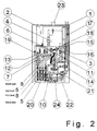
- the compact heating center is shown in the front view without cladding 17 and thermal insulation.
- the arrangement of the inner pipeline network e.g. with the distribution point 15 and the mixing point 6, the measuring, control and regulating devices with the check valves 12 and 13, the engine control valve 3, the distribution valve 11, the throttle device 18, the pumps 4 and 7 of the heating circuits and the pump 14 of the solar collector system, the circulation pump 16, the safety fitting groups for the drinking water gas technology and heating system 21 and 22, and the connecting lines to the heating circuits 5 and 8 in front of the thermal bath 1 and the hot water storage tank 2.
- the expansion tank 20 for the heating circuits and the safety tank for the solar collector system are located below the hot water tank 2 inside the casing.
- a particularly advantageous use of the compact heating center according to the invention relates to the supply of 85-360 m 2 of living space when using a modulating boiler 1 with a burner output of 6-29 kW, a hot water tank content of 520 l and a solar collector area of approximately 3.4 m 2 .
- the compact heating center described is particularly characterized by its high degree of prefabrication, the low on-site installation and the small space requirement, which makes it advantageous to use it in newly constructed houses with low-energy standards and fast installation times.
Landscapes
- Engineering & Computer Science (AREA)
- General Engineering & Computer Science (AREA)
- Chemical & Material Sciences (AREA)
- Thermal Sciences (AREA)
- Combustion & Propulsion (AREA)
- Mechanical Engineering (AREA)
- Physics & Mathematics (AREA)
- Life Sciences & Earth Sciences (AREA)
- Water Supply & Treatment (AREA)
- Sustainable Development (AREA)
- Sustainable Energy (AREA)
- Resistance Heating (AREA)
- Carbon And Carbon Compounds (AREA)
- Heat-Pump Type And Storage Water Heaters (AREA)
- Domestic Hot-Water Supply Systems And Details Of Heating Systems (AREA)
Applications Claiming Priority (2)
| Application Number | Priority Date | Filing Date | Title |
|---|---|---|---|
| DE29609069U | 1996-05-07 | ||
| DE29609069U DE29609069U1 (de) | 1996-05-07 | 1996-05-07 | Kompaktheizzentrale |
Publications (2)
| Publication Number | Publication Date |
|---|---|
| EP0806612A2 true EP0806612A2 (fr) | 1997-11-12 |
| EP0806612A3 EP0806612A3 (fr) | 1998-11-11 |
Family
ID=8024194
Family Applications (1)
| Application Number | Title | Priority Date | Filing Date |
|---|---|---|---|
| EP97250150A Withdrawn EP0806612A3 (fr) | 1996-05-07 | 1997-05-06 | Chaufferie compacte |
Country Status (2)
| Country | Link |
|---|---|
| EP (1) | EP0806612A3 (fr) |
| DE (1) | DE29609069U1 (fr) |
Cited By (7)
| Publication number | Priority date | Publication date | Assignee | Title |
|---|---|---|---|---|
| EP0961082A2 (fr) | 1998-05-29 | 1999-12-01 | Heinz Dötzl | Installation de chauffage et de préparation d'eau chaude |
| EP1304528A1 (fr) * | 2001-10-15 | 2003-04-23 | R.D.Z. S.p.A. | Module de distribution pour un circuit de chauffage ou refroidissement |
| EP1288581A3 (fr) * | 2001-08-31 | 2004-09-15 | Viessmann Werke GmbH & Co KG | Chaudière compacte |
| WO2009063308A3 (fr) * | 2007-11-16 | 2010-02-25 | O.T.M.A. S.N.C. Di Spaggiari & C. | Système combiné avec panneaux solaires et chaudière murale |
| ITMI20090527A1 (it) * | 2009-04-01 | 2010-10-02 | Gruppo Imar S P A | Modulo di collegamento idraulico alle utenze termiche di un impianto di climatizzazione bivalente ed impianto di climatizzazione includente tale modulo |
| WO2011038943A1 (fr) | 2009-09-29 | 2011-04-07 | Trezeta S.R.L. | Module de distribution, en particulier pour la distribution d'eau de chauffage ou de refroidissement |
| EP4641097A1 (fr) * | 2024-04-27 | 2025-10-29 | Hansa Heiztechnik GmbH | Système de gestion thermique destiné à être relié à une pompe à chaleur, système de chauffage associé et utilisation |
Families Citing this family (3)
| Publication number | Priority date | Publication date | Assignee | Title |
|---|---|---|---|---|
| DE29817899U1 (de) | 1998-10-01 | 1999-04-01 | Förster, Britta, 10245 Berlin | System für eine Energiestation im Bauwesen |
| DE10142779A1 (de) * | 2001-08-31 | 2003-03-27 | Viessmann Werke Kg | Kompaktheizgerät |
| DE102008023254A1 (de) * | 2008-05-05 | 2009-11-12 | Mhg Heiztechnik Gmbh | Kompakt-Heizzentrale |
Family Cites Families (2)
| Publication number | Priority date | Publication date | Assignee | Title |
|---|---|---|---|---|
| DE4407371A1 (de) * | 1994-03-05 | 1995-09-07 | Bosch Gmbh Robert | Heizgerät für Raumheizung und Brauchwassererwärmung |
| FR2733822B1 (fr) * | 1995-05-05 | 1998-10-02 | Financ & Comm Chablais | Module de distribution pour installation de chauffage central avec plancher chauffant et radiateurs |
-
1996
- 1996-05-07 DE DE29609069U patent/DE29609069U1/de not_active Expired - Lifetime
-
1997
- 1997-05-06 EP EP97250150A patent/EP0806612A3/fr not_active Withdrawn
Cited By (8)
| Publication number | Priority date | Publication date | Assignee | Title |
|---|---|---|---|---|
| EP0961082A2 (fr) | 1998-05-29 | 1999-12-01 | Heinz Dötzl | Installation de chauffage et de préparation d'eau chaude |
| EP0961082A3 (fr) * | 1998-05-29 | 2002-05-08 | Federspiel Ökotechnology Consulting GmbH | Installation de chauffage et de préparation d'eau chaude |
| EP1288581A3 (fr) * | 2001-08-31 | 2004-09-15 | Viessmann Werke GmbH & Co KG | Chaudière compacte |
| EP1304528A1 (fr) * | 2001-10-15 | 2003-04-23 | R.D.Z. S.p.A. | Module de distribution pour un circuit de chauffage ou refroidissement |
| WO2009063308A3 (fr) * | 2007-11-16 | 2010-02-25 | O.T.M.A. S.N.C. Di Spaggiari & C. | Système combiné avec panneaux solaires et chaudière murale |
| ITMI20090527A1 (it) * | 2009-04-01 | 2010-10-02 | Gruppo Imar S P A | Modulo di collegamento idraulico alle utenze termiche di un impianto di climatizzazione bivalente ed impianto di climatizzazione includente tale modulo |
| WO2011038943A1 (fr) | 2009-09-29 | 2011-04-07 | Trezeta S.R.L. | Module de distribution, en particulier pour la distribution d'eau de chauffage ou de refroidissement |
| EP4641097A1 (fr) * | 2024-04-27 | 2025-10-29 | Hansa Heiztechnik GmbH | Système de gestion thermique destiné à être relié à une pompe à chaleur, système de chauffage associé et utilisation |
Also Published As
| Publication number | Publication date |
|---|---|
| DE29609069U1 (de) | 1996-08-29 |
| EP0806612A3 (fr) | 1998-11-11 |
Similar Documents
| Publication | Publication Date | Title |
|---|---|---|
| WO2009095010A2 (fr) | Dispositif de chauffage | |
| EP2354677B1 (fr) | Utilisation de la chaleur du reflux de chauffage urbain | |
| EP3147574B1 (fr) | Vanne d'isolement pour un système de chauffage et système de chauffage | |
| CH623649A5 (fr) | ||
| EP0806612A2 (fr) | Chaufferie compacte | |
| DE102010014431B4 (de) | Verfahren und Vorrichtung zur Nutzung der Wärmeenergieresourcen eines Gebäudes | |
| DE10142779A1 (de) | Kompaktheizgerät | |
| DE102021211129A1 (de) | Hybridheizsystem zum Bereitstellen von Brauchwasser und Heizungswärme | |
| DE102007048728B4 (de) | Heizkessel, Heizungsanlage sowie Verfahren zum Betreiben einer Heizungsanlage, insbesondere zur solaren Heizungsunterstützung | |
| AT406905B (de) | Umlaufwasserheizer | |
| DE10259279B3 (de) | Versorgungssystem für Heiz-oder Kühlwasser sowie Verfahren zum Betreiben desselben | |
| DE3244373A1 (de) | Anlage zur luftheizung | |
| DE102011106022A1 (de) | Warmwassererzeugungs-, Speicher- und Abgabevorrichtung | |
| EP0544197A1 (fr) | Installation de chauffage à eau chaude pour bâtiments | |
| DE102006023627B4 (de) | Solaranlage | |
| EP0617236B1 (fr) | Accumulateur à utilisation multiple | |
| DE10102022A1 (de) | Wasserheizanlage | |
| DE102020127443A1 (de) | Klimatisierungsanlage für ein Gebäude | |
| DE19722822A1 (de) | Einrichtung zur Bereitstellung von Energie für eine Zentralheizung und für die Warmwasseraufbereitung | |
| DE20014094U1 (de) | Zentralheiz- bzw. Kühlvorrichtung | |
| DE2507044C3 (de) | Thermische Verteilerstation | |
| DE4142547A1 (de) | Heizgeraet fuer raumheizung und brauchwasserbereitung | |
| EP1288581A2 (fr) | Chaudière compacte | |
| DE3220697A1 (de) | Bivalent betriebene heizanlage | |
| EP4428448A1 (fr) | Procédé de rééquipement d'une installation de chauffage, installation de chauffage et utilisation |
Legal Events
| Date | Code | Title | Description |
|---|---|---|---|
| PUAI | Public reference made under article 153(3) epc to a published international application that has entered the european phase |
Free format text: ORIGINAL CODE: 0009012 |
|
| AK | Designated contracting states |
Kind code of ref document: A2 Designated state(s): AT BE CH DE LI NL |
|
| PUAL | Search report despatched |
Free format text: ORIGINAL CODE: 0009013 |
|
| AK | Designated contracting states |
Kind code of ref document: A3 Designated state(s): AT BE CH DE LI NL |
|
| RAP1 | Party data changed (applicant data changed or rights of an application transferred) |
Owner name: SCHMIDT, GUENTER |
|
| 17P | Request for examination filed |
Effective date: 19990504 |
|
| STAA | Information on the status of an ep patent application or granted ep patent |
Free format text: STATUS: THE APPLICATION IS DEEMED TO BE WITHDRAWN |
|
| 18D | Application deemed to be withdrawn |
Effective date: 20001201 |